1. Strengthening Mechanisms of Steel
In principle, the strength of steel is contributed by a number of strengthening mechanisms as follows [1] [2] :
–Intrinsic strength of ferritic iron;
–Solid solution strengthening;
–Precipitation strengthening;
–Grain size strengthening;
–Dislocation strengthening.
The yield strength (Δσy) can then be expressed as:
 (1)
(1)
In Equation (1), the strength has been expressed as a simple linear sum of individual strengthening mechanisms and has been applied in many cases extracting the different strengthening mechanisms in steels with bainitic microstructures [2] .
Charleux et al. [3] have discussed the validity of the summing of the strengthening components in expressing the degree of strengthening in the case of Nb-Ti low carbon bainitic (LCB) steels. According to them, it is necessary to consider the relative length scales and strength of the strengthening obstacles. If they are significantly different, a linear addition would be appropriate. For instance, strength of ferrous alloys is derived from the solid solution strengthening (including base strength of iron) and grain size strengthening. On the other hand, precipitation and dislocation strengthening arise from a similar density and strength of obstacles, which dislocate sample on the glide plane. For example, Foreman and Makin [4] obtained a Pythagorean flow stress addition law for discrete obstacles on the slip plane in the case where a similar density of relatively strong discrete obstacles (i.e. forest dislocations) and relatively weak obstacles (i.e. precipitates) are present. Therefore an alternative way to express the yield strength as a function of individual strengthening mechanisms is a sum equation where precipitation and dislocation strengthening obey a Pythagorean law:
 (2)
(2)
In the following sections different strengthening mechanism will be presented and discussed in detail.
1.1. Intrinsic Strength of Iron
The strength of ferritic iron without significant impurities has been estimated to be 85 - 88 MPa [5] in a low carbon ferritic steel and this can be considered as the base strength to which the other components will be added to estimate the overall yield strength.
1.2. Solid Solution Strengthening
Solid solution strengthening arises because the size differences between the solute and solvent atoms and the strain field that interferes with the dislocations as they move through the lattice causing plastic flow. The most significant factor behind the solid solution seems to be the size difference between solvent (in steels, Fe) and solute atoms, but there are also evidences that differences in shear modulus and the relative chemical differences contribute to solid solution strengthening. Although many of the factors, which contribute to the energetics of dislocation movement, are known and have been assessed in experimental studies, there is, as yet, no complete theory and, therefore it is not yet possible to predict the strengthening effect for a particular element from the first principles [6] .
Most practical approach to assess the solid solution strengthening is to use empirical relationships between alloying additions and tensile properties of steels. These equations are in form:
 (3)
(3)
where Ai = factor for strengthening resulting from 1.0 wt% addition of element i. Table 1 shows Ai values for some alloying elements generally used in LCB steels [2] [5] [7] .
A reasonable assumption for aforementioned elements is that a major portion of these element is in solid solution and available for solid solution strengthening, since with exception of Mo, these elements do not have a great tendency to precipitate out of solid solution as carbides, nitrides or other complex precipitates in steels. In
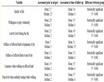
Table 1. Values Ai for some alloying elements generally used in LCB steels [2] [5] [7] .
the case of Mo, the possible precipitation of MoC does not cause significant underestimation of solid solution strengthening, since the Mo content of investigated steels and the factor of Mo are both low. The very significant solid solution strengthening of N that is often reported in the literature is assumed to be zero, since the presence of strong nitride formers renders it unlikely that any significant levels of N will remain in solid solution. Carbon in solid solution would also be expected to provide a high level of solid solution strengthening with coefficient of a similar order to that of nitrogen. However, the solubility of carbon in ferrite and steels contain strong carbide formers, such as Nb, Mo and Ti at ambient temperatures is very low, so that the contribution from carbon to solid solution strengthening is assumed to be negligible. In the B treated steels, Ti is added to bind N, so that the B addition can remain in solid solution and be in the form such that it can be effective for the transformation hardening. However, any significant contribution from solid solution strengthening from B, although being an interstitial atom, is not expectable since it tends to occupy the sites on prior austenite boundaries rather than interstitial sites in grain interiors [2] . Solid solution strengthening can be obtained from Si, Mn, Mo and Ni alloying. Siwecki et al. [8] observed the increase of strength by 30 MPa due to addition of 0.2 wt% of Mo in microalloyed steels, and also the change of yielding from discontinuous to continuous and improved heat affected zone toughness in Ti-V steels. According to Misra et al. [9] , simultaneous additions of 0.3% Cu and 0.15% Ni can further enhance yield strength by 32.4 MPa in a 690 MPa grade steel.
Table 2. Precipitate observed in 770 MPa Nb-Ti hot rolled steels
1.3. Precipitation Strengthening
Strengthening effect by the precipitates relies on their interaction with dislocations. Essentially, precipitation strengthening is achieved by producing a particulate dispersion of obstacles to dislocation movement, which are produced by the second phase precipitation process. The degree of strengthening is not only dependent upon the nature of the interaction of precipitates with dislocations, but also on the volume fraction and the size of particles. In general, there are several mechanisms that can contribute to increase in strength by the precipitation. These mechanisms include chemical hardening arising from the development of antiphase boundaries, when dislocation cuts through a particle, coherency strengthening, which relates to coherency strains developed in the matrix around a coherent precipitate and dispersion hardening due to looping of dislocations around the precipitates in so-called Orowan manner [10] .
Strengthening of Steels by Microalloy Precipitates
Three microalloy elements, namely Ti, Nb and V, are widely used as combinations to improve the mechanical properties of steels. A common feature of aforementioned microalloy elements is their tendency to react with C and N to form microalloy carbides, nitrides and carbonitrides, which can contribute to precipitation strengthening. Ti forms an extremely stable nitride, which is virtually insoluble in austenite and may be used for restricting grain grow growth during processing and removing nitrogen. Excess Ti can precipitate at lower temperatures as carbides, which contribute to precipitation strengthening [11] . Nb forms carbonitrides, which can precipitate quite readily in austenite under deformation (so called strain-induced precipitation) and resist recrystallization of austenite. Further precipitation of the remaining Nb in ferrite gives rise to precipitation strengthening [12] . V is the most soluble of the three microalloying and does not readily precipitate in austenite. VN is considerably stable compared to its carbides, so that their precipitation hardening is markedly enhanced with increasing N content in steel [12] . When precipitation of TiC, NbC or V(C, N) takes place during cooling after the hot rolling it may occur in two different ways. During the inter-phase precipitation, where nucleation occurs on the austenite-ferrite phase boundary, producing a particle-rich sheet at the location, where the boundary is temporarily halted. Alternatively, homogeneous nucleation and growth of carbonitrides may occur in the newly formed ferrite [13] . Classically, it was believed that total C in steel could not influence homogenous precipitation in ferrite due to low equilibrium solubility.
1.4. Grain Size Refinement Strengthening
Grain size refinement is one of the best-established strengthening methods in steels, as well as in other metals. The well-known Hall-Petch equation describes the relation between ferrite grain size and the yield strength.
 (4)
(4)
where σy = yield strength, σo = friction stress, ky = grain boundary resistance and d = grain size.
According to Equation (4) the yield strength is dependent on the reciprocal of square root of the grain size. This type of relationship has been shown to be valid for grain sizes down to about 1 μm [14] .
1.5. Dislocation Strengthening
An increase in dislocation density results in a strength increment, because further motion and production of dislocations becomes more difficult. Bainitic ferrite contains a higher dislocation density than polygonal ferrite, for a part of the dislocation substructure of the deformed parent austenite can be inherited by bainite (plastic relaxation) and the growth of bainite may be accompanied by the formation of dislocations in and around bainite (plastic accommodation) leading to additional strengthening [15] . The relationship between dislocation density and strength increment can be described by:
 (5)
(5)
where Δσ = the increase in yield strength, β = a constant, b = Burgers vector, G = shear modulus and ρ = dislocation strengthening.
According to Takahashi and Bhadeshia [16] , it might be assumed that for low alloy steels the dislocation density depends mainly on transformation temperature via the influence of latter on the strength of the parent and product phases. It should then be possible to treat all of the displacive transformations, such as martensite, bainite and Widmanstätten ferrite together. They have derived an empirical equation between the phase transformation and dislocation density (in m−2), which is valid over the range 570 - 920 K:
 (6)
(6)
where T = temperature in Kelvin.
Transmission electron microscopy has revealed a dislocation density of about 4 × 10¹⁴ m−2 for an alloy with bainite starting temperature, Bs around 650˚C. This compares with allotriomorphic ferrite obtained in same steel at 800˚C with a dislocation density of about 0.5 × 10¹⁴ m−2. Edmonds and Cochrane [17] reported a value of 1014 m−2 for the dislocation density, attributing to the yield strength by approximately 145 MPa. Hulka and Heisterkamp [18] gave a value of about 1.5 × 10¹⁴ m−2. The dislocation density seems to increase with decreasing transformation temperature. Irregular nature and high dislocation density are typical of low temperature transformation products (bainitic ferrite, acicular ferrite) formed under continuous cooling.
1.6. Total Strengthening
In total, the contributions of five strengthening mechanisms on yield strength (YS) level of 700 MPa strip are shown in Figure 1 [19] . However, even higher yield strengths of the order of 1030 MPa may be possible in HSLA steels with a fully bainitic structure. Simple summation is a simplistic case, marked deviations of the linearity in strengthening have been observed for mixtures of lower bainite/martensite [15] [20] .
2. Grain Refinement as a Unique Mechanism for Improving Strength and Toughness
2.1. Strength
The yield stress for bcc steels processed by different methods is plotted in Figure 2 as a function of the inverse square root of the grain size for grain sizes ranging from 45 to 0.2 µm. The ultrafine microstructures (grain size less than 2 µm) were produced by various techniques: the open symbols display the results from the severe plastic deformation (SPD) methods; the full symbols in gray represent the results from the advanced thermomechanical process routes (ATP); the full symbols in black show the results from the conventional route (Conv).
The lower yield strength of the 0.13C-0.67Mn-0.14Si (wt%) steel sheet produced by cold rolling and annealing [21] is shown by the solid diamond in Figure 2 where the grain size varied from 1.6 to 30 µm. The friction stress σi is about 100 MPa and the grain boundary resistance ky is 551 MPa µm1/2 [21] , according to the

Figure 1. Strengthening mechanisms yielding to the YS level of 700 MPa [19] .

Figure 2. Hall-Petch relationship in ultrafine grained bcc steels [22] -[26] . The open symbols display the results from the SPD methods; the full symbols in gray represent the results from the advanced thermomechanical process routes (ATP); the full symbols in black show the results from the conventional route (Conv). The straight lines show the Hall-Petch relation for different steels.
work of Morrison. Equal-channel angular pressing (ECAP) (at 623 K) followed by annealing at temperatures between 373 and 873 K produced steels with grain sizes ranging from about 0.23 to 10 µm in a low carbon (0.15C-1.1Mn-0.25Si, wt%) and a low alloy steel (0.15C-1.1Mn-0.25Si-0.06V, wt%) [22] . The ky value in Figure 2 (slope of bold line) is smaller in the steel processed by ECAP compared with the results of Morrison (dashed bold line). The yield stress for a grain size of 30 µm before ECAP is above the value predicted by Morrison, while the yield stress after ECAP is below the line. This phenomenon also reappears in other studies from both SPD and advanced thermomechanical processes [23] -[29] . That is, while the Hall-Petch relationship in steels may extend to the submicron range, the parameter ky may decrease. For steels with submicron grain sizes produced by ECAP, the yield stress for steels with a carbon content less than 0.1 wt% [23] [26] is notably smaller than for the steels with 0.15 wt% carbon [22] for a given grain size. The reason for this behavior is not fully understood, but could result from differences in grain size measurement. The data for samples with a dual phase microstructure (displayed by the sun symbol in Figure 2) [24] do not follow the line predicted by the Hall-Petch relationship as mentioned above. It seems that a smaller increment in stress is achieved in the dual phase steel when the ferrite grain size is refined from 19.4 to 0.8 µm. It is not clear whether this is related to some variation in the amount and morphology of the second phase after grain refinement.
It should be stressed that in early investigations by Morrison [21] , as shown in Figure 2, the different grain sizes were produced by cold rolling and subsequent annealing at different temperatures. This offered the advantage to alter only one parameter—the grain size. In the investigation by Song [29] , (where the initial motivation was not to measure the value of ky and σi in the Hall-Petch equation), the coarse microstructure consisted of conventional ferrite and pearlite. When refined into the ultrafine microstructure, however, it comprised ferrite and fine spheroidized cementite. A smaller ky value was found by Shin et al. [27] , which might also be attributed to the change in overall microstructure (along with grain size) in their study. By use of the ECAP technique, the initial coarse grained ferrite-pearlite microstructure was severely deformed. After four deformation passes, a microstructure with finer ferrite and a partially spheroidized pearlite was obtained. Thus, the smaller ky value in some studies on ultrafine ferrite might be the result of a reduction in the yield strength by replacing harder pearlite with softer ferrite and spheroidized cementite in the ultrafine microstructure. The presence of low misorientations between some grains in the ultrafine ferrite may also contribute to the reduced ky value in comparison to conventional “coarse” ferrite with high misorientations. It should be mentioned that most of the submicron microstructures measured for the SPD technique consist of large quantities of low-angle grain boundaries, and grain dimensions measured refer to the thickness of stretched microbands, which is not the same as average grain diameter. Further consideration of grain morphologies and appropriate characterization methods may be worthwhile to define the Hall-Petch relationship more accurately.
Unfortunately, the estimation of the contribution of the grain size in bainitic structures is more complicated than in simple ferritic steels. The nature of bainite, lath size and shape as well as carbide size and distribution, vary systematically with the temperature of transformation. All features are refined at low transformation temperatures. Furthermore, situation becomes far more complicated due to the fact that in bainitic structures, boundaries can be present with both low and high angle misorientations [2] . However in lath type, rather than polygonal structures, several publications suggest that the strength is related to reciprocal of some characteristic scale in microstructures, rather than d−1/2 type relationship in the Hall-Petch equation [2] [15] [28] . Hence, yield strength can be expressed as:
 (7)
(7)
where σy, σo and ky have identical meanings to Equation (4), but these have different values. The microstructural factor relating to grain size d in Equation (7) is not completely clear. Brozzo et al. [30] , in their studies on the low C bainitic steels, found a clear relationship between lath width and strength but only a weak correlation with packet size. This would indicate that slip across laths is the controlling factor.
2.2. Impact Toughness
Steel is still one of the traditional engineering materials widely used in industry. The high strength and high toughness steel is the most desirable product. However, in fact, strength and toughness are normally contrary. If the strength of steel increase its toughness normally decreases and vice versa. The composition and microstructure of the steel are primary factors controlling the strength and the toughness. Thus the grain refinement is a highly effective method to improve both the strength and the toughness [31] -[33] .
Toughness is conveniently characterized by the Charpy impact test [34] -[36] in terms of (i) the Charpy Transition Temperature (CTT), and (ii) the ductile-to-brittle transition appearance temperature, DBTT. CTT is evaluated, from the Charpy absorbed energy transition curve, as the absorbed energy corresponding to half the value of the upper shelf energy. The DBTT is defined as the temperature for 50% cleavage on the fracture surfaces of the Charpy impact specimens [37] [38] . Conventional coarse grain ferrite/pearlite (CGF/P) steels often show a close similarity of these two measures of transition temperature, that is CTT-DBTT. The high absorbed energy in the upper shelf region is associated with ductile fracture by micro-void coalescence (i.e. dimple rupture) whereas the low absorbed energy in the lower shelf region is associated with brittle cleavage fracture. In contrast, UGF/C steels had a DBTT was much lower than the CTT, attributed to the fact that the fracture mechanism of the ductile to brittle transition was caused by a different fracture mechanism: the decreased energy absorption by ductile fracture [38] .
For conventionally processed low carbon steels with ferrite grain sizes greater than 10 µm, Pickering’s classical work indicated that the ductile-to-brittle transition temperature (DBTT) is a function of strengthening mechanism [38] . For a yield strength increase of 9.8 MPa, if the strengthening is by dislocation, the DBTT will increase by 6 K; if by dispersion strengthening, the DBTT will increase by 4 K; if by grain-size refinement, however, the DBTT will decrease by 10 K. The effect of grain size on DBTT is characterized by Hall-Petch style formula:
 (8)
(8)
and
 (9)
(9)
where constants A and K depend on metallurgical factors other than the grain size, and d is grain size. With these relationships, it is expected that ultrafine grained steels would have improved impact toughness.
The reported impact toughness data from ultrafine grained steels are still limited, partly due to the difficulty in obtaining large enough specimens from the laboratory-scale samples. Figure 3 shows a set of recent results, comparing the DBTT of two steels with ferrite sizes of 6.8 and 1.3 µm, respectively. The upper shelf energy of the ultrafine grained steel is lower, and the transition region occurs over a wider range of temperature, compared with the coarser grained steel. The DBTT for the ultrafine grained steel is lower than the coarser grained steel. A detailed explanation of the DBTT curves is provided in references [39] [40] .
The DBTT results reported by Hanamura et al. [38] also confirm that the low-carbon steel with ultrafine grained ferrite/cementite microstructure has a much lower DBTT than that of the conventional ferrite/pearlite, quench/tempered, or quenched microstructure. Unlike results of Song et al., results of Hanamura et al. show the upper shelf energy of the ultrafine grained microstructure is as high as that of the coarser grained ferrite/pearlite microstructure for the same steel (Figure 4).
The effective grain size (deff) is a useful measurement to characterize the effect of grain size on impact toughness. Instead of using the directly measured grain size, Hanamura et al. [38] have proposed to use the effective grain size as the variable to measure the impact toughness. The deff is defined as the unit crack path in which a cleavage crack goes through in a straight fashion to form a facet, corresponding to the microstructural unit having a specific crystallographic orientation and bounded by large-angle grain boundaries. The deff can be experimentally measured from the fractography. Using the deff concept, the four types of microstructure are ranked as deff = 8 µm for the ultrafine grained ferrite/cementite (UF-F/C) microstructure, 20 µm for the ferrite/pearlite (F/P) microstructure, 25 µm for the quenched and tempered (Q/T) microstructure, and 100 µm for the as-quenched (Q) microstructure. This ranking is the same as the DBTT ranking, with smaller deff having a lower DBTT. Further,

Figure 3. Effect of test temperature on Charpy impact energy of two steels with different ferrite grain sizes [40] . The symbol dα indicates the average ferrite grain diameter. DBTT subsize refers to ductile-to-brittle transition temperature measured with sub-sized specimen (ligament size of 3 × 4 mm2).

Figure 4. Charpy impact energy as a function of test temperature for ferrite/pearlite (F/P), ultrafine ferrite/cementite (UF-F/C), as quenched (Q), and quench and tempered (Q/T) steels [38] .
it is found that the deff number is determined by the ferrite grain size for F/P, by the prior austenite grain size for Q, by the martensite packet size for Q/T, and by the ferrite grain size for UF-F/C microstructure. With such knowledge, the impact toughness can be tailored by the microstructure design. Statistically, the impact toughness for low-alloy steels follows an inverse trend against the yield strength, as shown in Figure 5, in which the shaded region on the left side of figure indicates the data distribution. Conventional quench and tempering (QT) can significantly increase the yield strength, but greatly decreases the impact energy. Ultrafine grained steels, as processed with the “tempforming” (TF) process, however, can have 16 times higher impact toughness than the conventional quench and tempered steel.
The extremely high impact toughness for this “tempformed” steel is owing to the ultrafine, elongated, fibrous ferrite grains with <110> crystalline orientation along the rolling direction, interspersed with nanometer-sized carbides. With such a microstructure, the fractured specimens showed fibrous delamination that is thought to relax the triaxial stress conditions ahead of the advancing crack tip, thus leading to high impact energy [41] .
3. Grain Refinement for Saving Materials and Saving Energy
Nowadays, the structural materials for aerospace, shipbuilding and offshore steels, pressure vessels and automotive applications and any other applications that are tied to power consumption are increasingly required to be energy efficient. The development of high-strength steel is an important way of reducing vehicle weight, amount of material used (reducing material cost) and achieving the purpose of energy saving and emission reduction.
The demand to produce automobiles which fulfill the requirements like, passenger safety, vehicle performance and fuel efficiency, has been the biggest challenge faced by the steel industry for the last couple of decades [42] [43] . In response the steel industry has developed advanced high strength steels (AHSS) including dual phase (DP), transformation induced plasticity (TRIP), complex phase (CP) and martensitic steels (MART). These steels are characterized by improved formability and crash worthiness compared to conventional steel grades, such as pearlitic steels. Currently, advanced high strength steels (AHSS) are extensively used in the auto industry and the projections are that the weight percentage of AHSS steel will increase to 35% by 2015, here as mild steel decrease from 55% to 29% in bodies and closures of light vehicles [44] . The rationales for increased use of the AHSS in the automotive industry are as follows: (1) the reduction of the car weight resulting from the use of high strength thinner gauge sheet steel, reducing the fuel consumption; (2) Increased passenger safety by an improved crash worthiness; (3) The strong competition from the light-weight materials, such as Al and Mg alloys and plastics. Figure 6 is a schematic of Volvo-2009 model [45] , showing the different classes of materials used for designing the car body.
Riding the trend, there is considerable effort to develop nanostructured steels that will meet such demands. But current effort has been focused on ultrafine-grain (UFG) ferrite single-phase steels, multi-phase steels, and nanostructured Bainite steels. Among various methods of strengthening steel, grain refinement is a method that can enhance strength with no deterioration in toughness [46] . In recent years, a variety of methods have been

Figure 5. Charpy V-notch impact energy absorption of the low-alloy steel as a function of yield strength at room temperature [41] . The steel that was “tempformed” at 500˚C (TF) shows large impact energy as compared to that of the steel that was conventionally quenched and tempered (QT), also at 500˚C. Annealing of TF steel at 700˚C degraded the impact energy to conventionally processed steels.

Figure 6. A schematic of Volvo-2009 model, showing the different class of materials used for designing the car body [45] .
developed to produce ultrafine-grained steels, including strain-induced ferrite transformation, large-strain warm deformation, intercritical hot rolling, multi-directional rolling and cold-rolling plus annealing of martensitic steel. The grain size is refined to 1 - 3 µm [47] -[49] . But in commercial hot-rolled Nb-Ti and Ti-Mo microalloyed strip steel, the grain size could be controlled within only 5 - 10 µm [1] [50] .
4. Methods of Producing Ultrafine Grained Steels
4.1. Production Ultrafine Grained Steels by Micro-Alloying
High-strength low-alloy (HSLA) steels are a class of steels developed to achieve properties superior to those of the ferritic + pearlitic steel and comparable to those of low alloy quenched and tempered martensitic steels. HSLA steels are designed to achieve their desired mechanical properties by the development of microstructures through controlled thermomechanical processing (TMP) and the steel is produced in its final form by a continuous hot deformation process, rolling, or forging, which comprise the TMP. Most HSLA steels are microalloyed with small additions (0.1 wt%) of niobium, vanadium, and titanium which control microstructural evolution during TMP through the formation of carbonitride precipitates.
With the development of the micro-alloying technology the elements of Nb, Ti, and V are used widely in the production to produce ultrafine grain steels (UFG-steels). During solidification from melt, they combine with C and/or N to form carbide, nitride and/or carbonitride precipitates. Figure 7 shows the correlation between the micro-alloying content and the solubility temperature for the precipitate present in steel 16 MnNi4 [51] . The solubility temperatures for the precipitates present in the steel are 1045˚C for the VC, 1130˚C for the VN, 1168˚C for the TiC, 1682˚C for the TiN, 1338˚C for the NbC and 1073˚C for the NbN [51] .
These fine precipitates play an effective role by retarding recrystallization (and therefore, increasing the recrystallization stop temperature) that usually follows deformation and thus, helps to retain the accumulated strain and deformed structures of austenite grains. There have been several studies on the recrystallization of carbon steels and Nb microalloyed steel [52] -[55] , and various models have been proposed for predicting the recrystallization of austenite.
4.2. Role of V Micro-Alloying
In high strength low alloy steels (HSLA), it is common practice to make additions of elements such as Ti, Nb, V for austenite grain size control [56] [57] . These elements have a high chemical affinity for N and C and form compounds, carbonitrides, which can control austenite grain growth. Special attention has to be paid to vanadium microalloying addition. Vanadium is a useful microalloying element which improves the mechanical properties of HSLA steels. In quenched and tempered steels, vanadium increases their hardenability and mechanical properties after tempering [58] . It can be used in dual role. Because of the high chemical affinity to nitrogen and carbon it forms carbonitrides V(C, N) which controls the austenite grain size. Dissolved vanadium decreases the rate of austenite decomposition and thus increases the hardenability. In high strength low alloy steels, an increase of hardenability at low austenite grain size was observed contrary to the effect of austenite grain size on the hardenability of common steels. This effect is explained by the Garbarz and Pickering hypothesis [59] that pinning the austenite grain boundaries by undissolved carbonitrides particles creates the possibility for segregation of dissolved alloying element atoms on immobile grain boundaries. The resulting decrease in the grain boundary energy reduces their potential for the nucleation of non-martensitic products as was observed in boron steels [60] .
4.3. Role of Nb Micro-Alloying
The use of niobium as microalloy element in steel for grain refinement is widespread. NbC usually precipitates after deformation of austenite, can pin dislocations so that recovery and recrystallization of deformed austenite can be intensively retarded [60] -[62] .

Figure 7. Correlation between the micro-alloying contents (M%) and the solubility temperature for the precipitates present in the steel 16 MnNi4 [51] .
Nowadays, most of ferritic-perlitic precipitation hardening steel grades are microalloyed steel. These steels after rolling or forging process would be cooled as completely controlled. The properties of these steel grades would be affected by solidification microstructures, thermomechanical process and cooling process after rolling [60] . Niobium has a three-fold influence on the mechanical properties of steel which are as grain size refinement during thermomechanical hot forming, precipitation hardening and lowering the γ to α transition temperature. Grain refinement is the only mechanism that simultaneously increases strength, toughness and ductility. Niobium-microalloyed steel has become a standard material in plate and strip for line pipe, automotive and construction use. Until now, the high potential of microalloyed high strength steel has not been used to the same extent in long products.
Nb(C, N) precipitates that have formed and grown at high temperature and in austenite phase prevent from grain coarsening in the subsequent stage of hot deformation. Other diffusion controlled process that occur with solution of niobium in austenite are retarding of austenite (γ) to ferrite (α) transformation that cause to increase nucleation of ferrite and reduce grain growth rate, forming of quasi-equivalence structures like bainite and finally appearance very fine Nb(C, N) precipitates during transformation that being coherent interface cause to increase strength with precipitation hardening mechanism [61] [62] .
4.4. Role of Ti Micro-Alloying
In modern industry, obtaining excellent combination of high strength and high toughness is a target for steel. It is well known that Nb, V and Ti microalloying elements play important roles in it [63] -[65] . While the microalloying elements precipitate as carbides or nitrides in austenite, the precipitates can lower the grain growth rate by pinning the grain boundaries [66] [67] . The obtained fine grain microstructure can enhance the strength and toughness of steels obviously [68] -[70] . Due to the high price of niobium and vanadium, the development of titanium microalloyed steels are attracted much more attention recently [71] -[74] . There are some researches of precipitation effects on microstructure and mechanical properties in Ti-bearing steels [74] -[76] . But steel alloyed with titanium alone is seldom studied especially in low carbon medium manganese martensitic steel. According to the thermodynamic analyses [77] [78] , the main forms of titanium precipitate are TiN, Ti4C2S2 and TiC or Ti(C, N) composite particles. The role of TiN particles in austenite grain size control is well known and the mechanism by which they exert this influence may be explained by Zener and Gladman’s expressions for pinning forces [1] [79] , which relate the size and fraction of precipitates. However, the precipitation temperatures for TiN, Ti4C2S2 and TiC particles are above 1500˚C, 1200˚C and 1000˚C, respectively. Due to the higher precipitation temperatures of TiN and Ti4C2S2 particle, they tend to grow to larger particles, and this is disadvantageous for the mechanical properties. Consequently, TiCs may have the most important effect on steel properties for their smaller size.
4.5. Role of Nb-Ti Micro-Alloying
The use of niobium and titanium as microalloy elements in steel for grain refinement is widespread. TiN precipitates, forming during solidification, can powerfully inhibit motion of austenite grain boundaries while NbC, which usually precipitates after deformation of austenite, can pin dislocations so that recovery and recrystallization of deformed austenite can be intensively retarded [80] [81] . It is generally believed that, when steels are heated up to austenite region, the TiN precipitates are the most stable and are known to have a dissolution temperature above the iron liquidus temperature but NbC precipitates dissolve away rapidly [82] [83] . However, when Nb and Ti co-existed in the same microalloyed steel, the effect of their interaction of formation and thermo-stability of precipitates, especially during solidification and austenization, was frequently neglected. The approximately solubility temperatures for the precipitates present in the produced steels are shown in Figure 7.
The different precipitates present in the steel due to Ti-Nb micro-alloying were analyzed in terms of size, morphology, and chemistry. They can be classified into types I - IV based on the size and morphology of the precipitates, and are summarized in Table2 Type I are rod-like intergranular (Fe, Mn)3C precipitates. The type II precipitates are TiN containing small amounts of Nb and are of the size range 120 - 500 nm. The type III precipitates identified as (Nb, Ti)C are ≈10 - 200 nm size and randomly distributed in the matrix, and type IV are spherical or needle-shaped (Nb, Ti)C precipitates (3 - 5 nm) that nucleated preferentially on sub-boundaries and dislocations in ferrite. Type I and II are generally undesirable from the viewpoint of toughness since they are known to promote cleavage fracture, while type III and IV are strengthening precipitates.
4.6. Role of Boron
Boron (B) can be an effective element in enhancing the hardenability of the steel and in obtaining a bainite and/or martensite dominant structure. As a typical feature of B is its alloying of trace amounts; the controlled concentration of B is ranging from 10 ppm to 30 ppm. B alloying is not indispensable in low carbon bainitic (LCB) steels and it is not always used in steels with yield strength from 500 MPa to700 MPa [84] . On the other hand, for the LCB steels with yield strengths above 700 MPa [85] , such as X120 line-pipe steels, B alloying is found to be crucial in order to promote required lower bainitic microstructures for high strength and toughness, besides improving the weldability and maintaining alloying cost at low levels. The hardenability-enhanced effect of B is based on its non-equilibrium segregation at grain boundaries. There are several explanations, how this type of segregation improves the hardenability of steels [86] :
—The non-equilibrium segregation to austenite grain boundaries reduces the grain boundary energy and prevents nucleation of ferrite.
—B can reduce the coefficient of self-diffusion of iron at grain boundaries, thereby reducing the nucleation sites for ferrite. Since the grain boundaries are preferential nucleation sites for ferrite, when B segregates to grain boundaries, these sites will become ineffective.
—Fine borides form along the grain boundaries. Being coherent with the matrix, ferrite is difficult to nucleate at the interface between boride and matrix. (This explanation contradicts with the assumption of atomistic B being effective in enhancing the hardenability).
In general, low carbon micro-alloyed steels have 0.05 wt% C and 1.5 wt% Mn and utilize micro-alloying concepts to attain a fine-grained microstructure. The fundamental basis for the development of ultra-high strength 770 MPa hot rolled steel is to obtain ferrite-bainite microstructure in the hot rolled product through controlled rolling and alloy design. The two main elements considered for obtaining a bainitic microstructure were boron and molybdenum. Boron retards the nucleation of ferrite by segregating to austenite-ferrite boundaries, where it inhibits ferrite nucleation through strong interaction with lattice defects such as dislocations and vacancies [87] [89] . Thus, boron effectively moves the ferrite C-curve to longer times.
4.7. Role of Vanadium-Nitrogen Micro-Alloying
The mechanism of grain refinement caused by addition of nitrogen has been extensively investigated. Ochi et al. [90] suggested that N promote the formation of intragranular ferrite, and refine the grain in vanadium steel. Wang et al. [91] further confirmed that the addition of N to V microalloyed steel could make more vanadiumcontaining precipitates in the form of carbonitrides which acted as nucleus of ferrite formation, and raised the nucleation rate of ferrite, as well as resulted in grain refinement of ferrite. It well known that, vanadium carbides did not take part in pinning process. On the contrary, vanadium carbonitrides can be assumed to have a higher solution temperature than pure vanadium carbides, between 1000˚C and 1200˚C, depending on the vanadium and nitrogen content [57] .
Zhao et al. [92] indicated that, in ferritic-pearlitic microalloyed steel, the area fraction of ferrite increased from 21% to 38%, and the averaged grain size decreased from 10.3 µm to 6.2 µm, when the nitrogen content was enhanced from 30 ppm to 210 ppm and normalization was performed at 930˚C. An increase in reheating temperature brought elevated strength at an expense of toughness. Improved combination of yielding strength in 650 MPa and toughness in 48 J at −20˚C can be obtained in 33 Mn2V stee1 with nitrogen content of 140 ppm at reheating temperature of around 930’C [92] .
On the other hand, the higher silicon contents in SiV and SiVN steels increase the activity of carbon in these alloys thus stabilizing carbides and carbonitrides [93] . Therefore, the austenitizing temperature of 1200˚C (heat treatment temperature of investigated HSLA steels) is necessarily not high enough to dissolve all VN or V(C, N) particles and some of them likely restricted the austenite grain growth during the heat treatment. This was, further, confirmed by IDS calculation which gave the following temperatures for the start of precipitation of VN: 1085˚C for 38 MnSiV5, 1120˚C for SiV and 1265˚C for SiVN, respectively [93] . Another explanation for the finer ferritic grain size in vanadium containing steels is the inter-phase precipitation of vanadium carbonitrides which slows down the austenite-ferrite transformation giving more time for ferrite nucleation [94] [95] . According to the results of this study it is not excluded that also a high silicon (Si > 1%) causes a smaller ferritic grain size, e.g. through higher AR3 temperature since the nucleation of ferrite starts earlier.
4.8. Summary
In practice, more than one microalloying element is often added, each for a different purpose. Hence, the low solubility of TiN makes it a good choice to restrain grain growth during reheating. Nb(C, N) is only sparingly soluble below 1000˚C, and it is a good choice if one wishes either to restrain grain growth below this temperature or more importantly to precipitate in deformed austenite. Excess Ti, Nb can precipitate at lower temperatures as carbides, which contribute to precipitation strengthening. VC, on the other hand, is much more soluble and is added so that it can remain in solution and precipitate later, forming a fine hardening dispersion in the ferrite. The presence of more than one alloying element can result in the precipitation of complex multi-component carbonitrides such as (Nb, V) (C, N) or (Nb, Ti) (C, N). The solubility of those complex carbonitrides can be found to a first approximation from the solubility of the individual carbides and nitrides. Finally, Nb and Ti can be added to low alloy steels to form carbides and nitrides with a totally different purpose. In the “interstitial free” steels, Nb and Ti are added to act as “scavengers” for C and N. They form low-solubility precipitates that result in an almost interstitial free ferrite.
4.9. Production Ultrafine Grained Steels by Heat Treatment
Grain refinement is an effective way to improve both strength and toughness. Since the grain size of austenite decomposition products decreases with decreasing austenite grain size, many efforts have been made to refine austenite grains. In the Thermo Mechanical Controlled Processes (TMCP), recrystallization andnon-recrystallization rolling are used to refine austenite grain, of which the minimum size or thickness is 10 - 20 µm in C-Mn steels and 5 - 10 µm in steels microalloyed with Ti and Nb [96] . Controlled austenitization is another effective way to obtain ultrafine grained austenite in heat treatment steels, such as rapid cyclic transformation, reversion from tempered and cold rolled martensite. The former, which includes 2 - 4 cycles of rapid austenite-martensite transformation, was employed to obtain austenite grain of 1 - 10 µm [97] -[99] . The latter including tempering and further heavily cold rolling was attempted to refine austenite grain size to 1 - 5 µm [100] [101] .
4.9.1. Phase Transformation through Cyclic Heat Treatment
Grain size refinement of steel, by temperature cycling can be done by repeated alpha-gamma phase transformations [102] [103] . One of the effective methods of the previous austenite refinement is refinement by temperature cycling, i.e., by cyclical repeated heating and cooling of steel. Refinement of steel microstructure by temperature cycling can be achieved by a cooling rate that provide diffusional transformations of austenite to pearlite, or by rates that provide transformations of austenite to bainite, or diffusion-less transformation to martensite [104] -[106] .
4.9.2. Cyclic Quenching Method (Repetitive Rapid Heating and Quenching)
In previous works, the effect of heating rate on the refinement of steel austenite using a mixture of bainitic ferrite and retained austenite as the starting material were studied. During conventional continuous heating rate, as ranged from 2˚C/s to 100˚C/s which is related to a moderate superheating, would allow the austenite grains to direct grow from the previous retained austenite present in the initial microstructure, along the ferrite plate. In this case, the austenite will inevitably grow in an acicular morphology until the original austenite grain structure is recovered without request for nucleation of new austenite grain, resulting in the so-called memory effect and little grain refinement [107] . Some other early works [108] [109] also reported the similar observations. However, when a very slow continuous heating is imposed and correspondingly a limited superheating achieved though, the retained austenite decomposition into the cementite or carbide can occur in an initial bainitic or martensitic steel, as in the 2.25Cr-1Mo steel for example [110] , on early heating stage. This will destroy the memory effect and lead to new austenite nucleation at prior austenite grain boundaries and the precipitates on the following austenitization heating.
On the other hand, a high degree of superheating, as a result of extremely rapid heating to an elevated austenitisation temperature, will significantly increase both the driving force for reverse α → γ reaction and atom mobility. This make it possible for some new austenite grains to nucleate at all possible sites, including the prior austenite grain boundaries, the adjacent ferrite plate interfaces and even inside the plates, even if the retained austenite film will thicken simultaneously. The austenite will then grow at a high nucleation ratio and develop an equiaxed and ultrafine-grained morphology. This suggests that the austenite grain can be effectively refined when extremely rapid cyclic α → γ → α phase transformation occurs in a mixture of bainitic ferrite and retained austenite under a high superheating situation.
In earlier work done by Wang et al. [110] , they were studied the effect of extremely high degree of super heating on the refinement of steel austenite. They stated that, An extremely high degree of superheating for the reverse α → γ transformation, which was successfully performed in a initial microstructure composed of bainitic ferrite and retained austenite as a result of extremely rapid resistance heating up to an elevated austenitization temperature, can prevent restoration of the previous coarse-grained austenite and lead to the formation of an ultrafine structure during the subsequent rapid cooling.
4.10. Production Ultrafine Steels by Advanced Thermomechanical Processes
Recent researches involving metallic materials can lead to technological innovations [111] . Both advanced thermomechanical processes and severe plastic deformation strategies have been developed to obtain ultrafine ferrite grain with size close to 1 μm in low-carbon low-alloy steels [37] . Advanced thermomechanical processes involving modification to conventional large-scale processes can be optimized to operate in deformation conditions where they beneficially exploit solid-solid reactions such as recrystallization, precipitation, and phase transformation. Ultrafine grain size has been obtained in steels through deformation near or in the intercritical region by exploiting strain-induced dynamic transformation [112] -[114] . Ferrite dynamic recrystallization can be exploited straining in warm condition inside the ferrite domain [115] [116] . Also, ultrafine or nanocrystalline structures has been achieved by warm or cold deformation of martensite starting microstructure [117] -[119] .
Two types of procedures are used to deform austenite: conventional or controlled thermomechanical processing [120] . The former consists of multi-deformation schedules aimed at changing the shape, while the second also aims to control the microstructural evolution. Controlled thermomechanical processing has been successfully industrialized in modern steel mills and can be defined as disciplined deformation schedules under continuous cooling and controlled conditions, aimed at attaining fine-grained microstructures [121] -[123] . This kind of processing can be separated in four different stages, as the temperature decreases. Figure 8 is a sche-

Figure 8. Schematic representation of the thermomechanical treatment for microalloyed steel, indicating the critical temperatures [126] .
matic representation of the thermomechanical treatment for microalloyed steel, indicating the critical temperatures (Ts, Tnr, AR3, and AR1). In the first stage, grains coarsened by soaking at temperatures above Ts are refined by the repetition of deformations and recrystallizations at high temperatures. The second stage takes place under conditions in which recrystallization is no longer completed during inter pass times due to strain-induced precipitation [124] [125] , i.e., below the non recrystallization temperature (Tnr). Grains in this stage have a pancake-like shape and dislocation substructures are created inside the grains.
In the third stage, deformation takes place in the phase transition region, i.e., in the temperature range between the start of ferrite formation (AR3) and the end of ferrite transformation (AR1). Ferrite nucleates within and at grain boundaries. In this stage, austenite continues to deform and the transformed ferrite begins to be strained. In the fourth stage, a variety of microstructures can be obtained during cooling, depending on the cooling rate and the stage in which the deformation was interrupted. After the first deformation stage, when the material is air-cooled, the ferrite grains are relatively large due to grain growth during cooling. After the second stage, the grains are smaller. In the third stage, increasing the cooling rate causes the grains to become finer and substructural dislocation occurs inside the strained ferrite grains. During conventional thermomechanical processing, the multi-deformation schedule is similar to that of the first stage, where the recrystallization kinetics is very fast. Thus, static recrystallization occurs during inter pass times and no strain accumulates from one pass to another. It is well-established that the start temperature of ferrite formation (AR3) and the end temperature of this transformation (AR1) depend on the cooling rate. These temperatures decrease as the cooling rate is increased. When higher cooling rates are imposed, austenite is present at temperatures below that of equilibrium between the phases (Ae3 and Ae1). Thus, it is possible to deform unstable austenite [37] -[116] . Upon deformation, strain-induced dynamic phase transformation (austenite to ferrite) can take place. New ferrite grains and transformed ferrite during cooling are strained together with austenite and continuous dynamic recrystallization of ferrite can occur. This technique has been used to produce ferrite grain sizes as fine as 2 - 5 µm via recrystallization-controlled rolling or by conventional rolling followed by accelerated cooling [127] .
4.10.1. Recrystallization of Austenite during Hot Deformation
An important mechanism that is widely used for grain refinement in steels is dynamic recrystallization during hot deformation [128] . This technique has been used to produce ferrite grain sizes as fine as 2 - 5 µm via recrystallization-controlled rolling or by conventional rolling followed by accelerated cooling. In recrystallizationcontrolled rolling fine precipitates restrict austenite grain growth after deformation. Recrystallization controlled rolling is often used in conjunction with accelerated cooling and micro-alloying in order to effectively refine the grain size. Accelerated cooling is used to increase the cooling rate through the transformation zone in order to decrease the transformation temperature. In principle, a lower transformation temperature results in a higher ferrite nucleation rate due to a higher under cooling, and a decreased growth rate. Conventional controlled rolling has been implemented in many commercial operations through the addition of microalloying elements especially strong carbide/nitride formers elements. The addition of small amounts (>0.1 wt%) of strong carbide/nitride formers elements such as Nb, Ti, V, and Zr, with Al also normally present, to the austenite (‘‘microalloying’’) is extremely important in commercial low alloy steels. Their main role is to precipitate from austenite-forming carbides/nitrides or complex carbonitrides. The solubility of these elements is small, so that high austenitizing temperatures in excess of 1100˚C are usually required. This increases the density of sites for ferrite nucleation. The lowest solubility product is that of TiN followed by NbC, TiC, and VN, with VC being by far the most soluble carbide. Precipitation processes from the austenite can be divided in three groups:
1) Precipitation from undeformed austenite: this can happen after reheating of the steel or during cooling from a high soaking temperature. The carbides/nitrides formed in this way, with size = 20 nm, are intended to restrain grain growth by pinning the grain boundaries.
2) Precipitation from deformed austenite: it is normally accepted that deformation significantly accelerates precipitation. In turn, this precipitation can delay the onset of austenite recrystallization that is invaluable for the controlled rolling of the austenite.
3) Precipitation during austenite-ferrite transformation: if enough alloying element remains in solid solution after high-temperature processing, carbide/nitride precipitation can occur during the austenite-ferrite transformation. These precipitates form at the austenite-ferrite transformation front resulting in precipitates arranged in parallel planes, which is often called interphase precipitation.
4.10.2. The Martensite Thermomechanical Treatment
Martensite treatment is one of the known thermo-mechanical processes that can be used for the grain refinement of metastable austenitic stainless steels [129] . The as-cast specimens were first homogenized and then hot forged in order to prepare a suitable microstructure for the subsequent martensite treatment. This treatment may be consisted of single [130] [131] or repetitive [132] [134] stages of cold rolling followed by reversion annealing. In single stage, cold rolling was carried out with the reductions of 10% - 95% followed by annealing at temperature of 850˚C for 15 - 1800 s, as shown in Figure 9. This process results indicated that the specimen was reversion-annealed at 850˚C for 30 s exhibited the smallest average austenite grain size of 65 nm with more than 86% austenite [130] . In repetitive martensite thermomechanical treatment, the first stage was consisted of cold rolling to 70% thickness reduction followed by annealing at 850˚C for short annealing durations (60 second), while the second stage was comprised of cold rolling to 60% thickness reduction followed by annealing at 850˚C up to 60 second, as shown in Figure 10. The smallest grain size of 80 ± 10 nm with a microstructure consisted of austenite and small amount of retained martensite was achieved by secondary annealing for 30 s. Increasing the annealing time to 60 second led to the formation of fully austenitic microstructure but the grain size of about 260 ± 40 nm. This microstructure possessed the yield strength of 1 GPa and the total elongation of 30% [132] . Table 3 and Table 4 show the single/ repetitive martensite thermomechanical treatment for different ultrafine grain austenitic stainless steel.
Table 3. Effects of different processing parameters on mechanical properties of 301 nano-ultrafine steel [133] .
Table 4. Mechanical properties of 201L stainless steel at different stages of the repetitive thermo-mechanical process at room temperature [130] .
aSA: solution annealing; CR: cold rolling.

Figure 9. Schematic illustration of the thermomechanical process to obtain the nano grained structure in a 201L stainless steel, As and Ar are the reverse transformation start and finish temperatures, respectively [130] .

Figure 10. Schematic illustration of the repetitive thermomechanical process used to obtain nan/ultrafine grain structure in 201 stainless steel [132] .
4.10.3. Strain-Induced Ferrite Transformation
Refinement of ferrite grains is a promising way to simultaneously improve both the tensile strength and toughness of steels [135] . Up to now, several different thermomechanical controlled processing (TMCP) routes have been conducted in steel industry to refine ferrite grains [136] -[141] . However, the grain refinement during TMCP is limited to 5 µm [142] [143] . In the last decade, researchers have developed new thermo-mechanical processes to produce fine ferrite grains in the range of 1 - 3 µm [144] -[146] . Among these approaches, ultra fine ferrite (UFF) formation through dynamic strain induced transformation of austenite to ferrite (DSIT) is a simple and most effective way [143] [144] . DSIT includes transformation of austenite to ferrite during rather than after deformation. It has been found that plastic strain increases the austenite to ferrite transformation temperature (AR3) [147] . Therefore, if steel is deformed at temperatures just above AR3, the transformation temperature increases and reaches to deformation temperature provided that the sufficient amount of plastic strain can be imposed on austenite phase. In these conditions, ferrite phase is dynamically formed during deformation process. The critical strain in the range of 0.1 to 0.8 is required for initiation of DSIT [147] . The principles of DSIT are shown in Figure 11. The critical temperature for DSIT is usually just above the AR3 temperature. It has also been demonstrated that DSIT can occur if deformation applied in the austenite meta-stable temperature range between Ae3 and AR3 [148] . All the dynamic evolving behaviors of microstructure at lower deformation temperature range between Ae3 and AR3 were similar to that at AR3. The volume fraction of ferrite increased with increasing the amount of deformation, and most of the strain-induced ferrite were found to nucleate on the boundaries of ultrafine austenite grains, including a lot of them preferentially selected the corner as their nucleation sites. The reason should be mostly attributed to the change of carbon diffusion behavior due to the refinement of austenite grains.

Figure 11. Principles of dynamic strain induced transformation during deformation at constant temperature [148] .
4.10.4. Large-Strain Warm Deformation
In recent years, a variety of methods have been developed to produce ultrafine-grained (UFG) materials with a ferrite grain size of around 1 µm [149] [150] . Many investigators [37] [38] [96] used large-strain warm deformation as most important thermomechanical technique to produce ultrafine grained steel.
Large-strain deformation processing schedules for production ultrafine grained steel are outlined in Figure 12. It consists of 3 min of reaustenitization at 912˚C and a single-pass deformation at 860˚C applying a logarithmic strain of ε = 0.3 at a strain rate of 10 s−1 above the recrystallization temperature. In the conventional hot rolling route (Figure 12(a)), the sample is then air cooled to room temperature to obtain a conventional ferrite-pearlite starting microstructure with ferrite grain size around 12 µm. Grain refinement is achieved by subsequent largestrain warm deformation at 700˚C (the fine grained (FG) route, Figure 12(b)) and at 550˚C (the UFG route, Figure 12(c)), respectively. A total strain of 1.6 is realized by a four-step flat compression series, each step exerting a strain of 0.4 at a strain rate of 10 s−1. The deformation temperature controls the degree of grain refinement. At 700˚C, a fine polygonal ferrite matrix with globular cementite and fine pearlite colonies is formed. At 550˚C, continuous grain subdivision and pronounced recovery lead to slightly elongated ferrite grains with a grain size of around 1 µm [151] . After warm deformation, specimens were annealed for 2 h at the respective deformation temperature to simulate coiling at elevated temperatures, and then air cooled to room temperature.
On the other hand, previous works illustrate that; to control the finished microstructure, large-strain induced deformation process may be followed by inter-critical annealing to produce dual phase steel [25] . To obtain the final dual-phase microstructure, all specimens were subjected to inter-critical annealing followed by quenching in order to transform all austenite into martensite/bainite/pearlite depend on cooling rate of quenching media.
Plain carbon-manganese steel was subjected under the previous treatment by Calcagnotto et al. [152] . They concluded that, after inter-critical annealing at 730˚C followed by water quenching, the microstructure obtained in case of hot deformation consists of a ferrite matrix with a grain size of 12.4 µm and 31.3 vol% martensite, the latter occurring partly as isolated islands, partly as aligned bands. By applying multi-pass warm deformation at 700˚C (fine grained route) and at 550˚C (ultrafine grained route) between hot deformation and intercritical annealing, the ferrite grain size is reduced to 2.4 and 1.2 µm, respectively. The martensite fraction is 30.1 vol% in the fine grained steel and 29.8 vol% in the ultrafine grained steel. Exemplary micrographs are shown in Figure 13.
4.10.5. Multistage and Single-Stage High-Speed Compression
Figure 14 shows the thermal processing history in the multistage and single-stage high-speed compression tests, which were based on the Super Short interval Multi-pass Rolling (SSMR) process. The work pieces were gradually heated at a rate of 10˚C/s from room temperature to 1000˚C, maintained at the this temperature for 120 s,
 (a) (b) (c)
Figure 12. thermomechanical processing routes to produce different grain size in a hot deformation simulator. All treatment are followed by an intercritical annealing at 730˚C for 3 min and subsequent quenching to obtain the final ferrite/martensite daul-phase microstructur. Ar3: non-equilbruim transformation start temperature; Pf: pearlite transformation finish temperature; ε: logarithmic starin [152] . (a) Coarse grain (CG) route; (b) Fine grain (FG) route; (c) Ultrafine grain (UFG) route.

Figure 13. Microstructures of the (a) Conventional material (12.4 µm ferrite grain size); (b) Fine grained material (2.4 µm ferrite grain size) and (c) ultrafine grained material (1.2 µm ferrite grain size) produced by the processing routes illustrated in Figure 10 plus intercritical annealing for 3 min at 730˚C in a salt bath, followed by water quenching [152] .

Figure 14. Thermal processing history in multistage and single-stage compression tests [154] .
and then cooled at a rate of 50˚C/s to the testing temperature of 800˚C or 850˚C. The austenite grain size before compression was about 30 µm [153] . Before compression, there was a holding time of 5 second at the testing temperature to minimize the temperature distribution inside the work piece. The axial reductions of the different stages were 50%, 40%, and 50% and the corresponding strain rates of the different stages were 75/s, 150/s, and 300/s, respectively. Severe plastic deformation at a temperature of approximately Ae3 is effective for producing ultrafine-grained plain steel because the accumulated strain can immediately induce a ferrite transformation. However, owing to the heat generation associated with severe deformation, the processing temperature easily rises to above Ae3. Consequently, it was necessary to remove the heat, and in the test process, the test pieces were cooled by mist spray between stages. A single-stage high speed compression test was also conducted. The heating pattern in the single-stage test was almost the same as that in the multistage compression test, but the testing temperature was slightly reduced to 760˚C. The axial reduction was 78% and the strain rate was 300/s. This is because severe single stage compression generates considerable heat, and thus the test must be started earlier at a lower temperature to produce a stable ferrite structure.
4.10.6. Rapid Cooling and Short Interval Multi-Pass Hot Rolling
Toshiro et al. [155] discover a noble grain refinement method to attain ferrite grain size of 1 µm in plain C-Mn steel by multi-pass hot rolling in a stable austenite temperature region. 0.1%C-1%Mn and 0.16%C-0.7%Mn steels were finish-rolled at about Ae3 and then rapidly cooled. Special emphases have been placed on the interval, Δt, between the finish of rolling and the start of water spray cooling of more than 1000˚C∙s−1 in cooling rate and the interval between the last two rolling passes. By reducing Δt from 0.5 to 0.05 s alone, the grain sizes near the sheet surface and in the central region were markedly reduced to 1.3 and 2.2 µm respectively. By reducing Δt and the rolling pass interval together, a further reduction in grain size was then achieved. Consequently, the steel sheet in which the ultrafine grain structure of about 1 µm in grain size penetrated from the sheet surface to the depth of a quarter of the sheet thickness and the grain size in the central region was well below 2 µm was obtained. The transformation to the ultrafine ferrite is considered to be static and from deformed austenite (γ).
The principal of rapid cooling and short interval multi-pass hot rolling is schematically represented in Figure 15. It consists of three rolling stands designated as F1 to F3 and water-cooling devices. The cooling device after F3 was designed to attain a large cooling rate over 1000˚C∙s−1 for the samples under investigation and to control the intervening time period Δt between the last rolling pass and the beginning of the rapid cooling. The Δt in this experiment is specifically defined as the period between the instance of the exit from the last rolling and the instance at which high-pressure water jets first make contact with samples. The cooling devices between the rolling stands were used to suppress adiabatic deformation heating when it was necessary to maintain sample temperature.
4.11. Concept of “SSMR” Process
To make the short interval multi-pass rolling process function well, reduction per pass, inter-pass time, number of passes and rolling temperature should be optimized. Rolling temperature affects the rolling load as well as the reduction per pass. The lower the material temperature is, the larger the rolling load becomes. In addition, if the temperature falls below the ferrite transformation temperature before the final pass, the microstructure of the rolled strip is supposed to contain deformed ferrite grains or abnormally grown grains, which are not preferable for mechanical properties of the strip. Therefore the rolling in the stable austenite temperature region was searched for the new process. In order to shorten the inter-pass time, the rolling stands must be placed close each other and rolling speed must be fast. However, when the rolling speed increases, the heat generation in rolling becomes large. For the purpose of the effective strain accumulation, excessive temperature rise should be avoided because the restoration of the strain proceeds fast in high temperature. Therefore the rapid cooling right after each rolling pass is necessary to compensate the generated heat. Immediate cooling after rolling is also required for inducing ferrite transformation and for restraining the grain growth after the transformation. The basic

Figure 15. Schematic representation of experimental hot-rolling simulator [156] .
concept of the newly proposed process is as follows. In downstream stands of hot finishing mill, more than two stands including the final one are equipped at extremely short distance. At those stands high speed and moderately large reduction rolling of 40% - 50% per pass is performed. Strip temperature is controlled around Ae3, the para-equilibrium transformation temperature from austenite to ferrite, by inter-pass cooling. Then the strip is cooled down to appropriate temperature immediately. Authors named this process “Super Short interval Multipass Rolling (SSMR) process”.
4.12. Production Ultrafine Steels by Severe Plastic Deformation Techniques
Severe plastic deformation (SPD) techniques [157] -[159] impose large accumulated plastic strains at room or elevated temperatures, e.g. mainly in the temperature regime of warm deformation. Many different severe plastic deformation (SPD) processing techniques have been proposed, developed and evaluated. These techniques include equal-channel angular pressing (ECAP) [160] -[162] , high-pressure torsion (HPT) [163] -[165] , multi-directional forging [166] -[168] , twist extrusion [169] [170] , cyclic-extrusion-compression [171] [172] , reciprocating extrusion [173] [174] , repetitive corrugation and straightening (RCS) [175] [176] , constrained groove pressing (CGP) [177] , cylinder covered compression (CCC) [178] , accumulative roll-bonding (ARB) [179] [180] , friction stir processing (FSP) [181] [182] and submerged friction stir processing (SFSP) [183] . All of these procedures are capable of introducing large plastic straining and significant microstructural refinement in bulk crystalline solids. Some of these techniques, such as ECAP, HPT, multi-directional forging and ARB, are already well-established methods for producing UFG materials where, depending upon the crystal structure, the processed microstructures have grain sizes lying typically within the range of ≈70 - 500 nm. The other techniques are currently under development for this purpose.
4.12.1. Equal-Channel Angular Pressing
Equal-channel angular pressing imposes large plastic strains on massive billets via a pure shear strain state. The approach was developed by Segal et al. in the early 1980s [184] . Its goal was to introduce intense plastic strain into materials without changing the cross-sectional area of the deformed billets. Owing to this characteristic, repeated deformation is possible. At the beginning of the 1990s this method was further developed and applied as a severe plastic deformation method for the processing of microstructures with submicron grain sizes [185] . The equal channel angular pressing method was mainly applied for nonferrous alloys (e.g. Al and Mg alloys) and some low carbon steels. The finest ferrite grain size obtained by use of this method is reportedly about 0.2 µm [186] [187] .
The ECAP technique was invented as a method for the shape-maintaining plastic deformation of bulk materials in [188] and for the first time has been shown to be applicable for the formation of an ultra-fine grained structure in metals and alloys in [189] . The method utilizes a die containing two channels of equal cross sections intersecting at an angle 2Φ, which normally varies in the range 90˚ - 135˚ (Figure 16). In the vicinity of the plane of intersection of these channels material undergoes severe plastic deformation, which is mainly of simple shear character. On passing the two channels a sample maintains its shape except for small portions at the ends (Figure 3). There have been done many analyses of the mechanics of deformation during ECAP to understand
 (a)
(a) (b)
(b)
Figure 16. Schematic view of equal channel angular pressing [190] .
the exact character of plastic strain during ECAP, its dependence on the location of material elements with respect to the channel walls and to evaluate the accumulated strain [190] -[193] . The simplest approximation is the model of simple shear according to which materials is subject to simple shear strain of ε = 2/√3cot(Φ/2) singularly at the plane of channels’ intersection [190] . For 2Φ = 90˚ the highest strain per pass equal to ε = 1.15 is achieved. Dies with such an angle are used for pure metals and easily deformable alloys. For hard-to-deform materials strain is imposed at elevated temperatures and/or with the channels' intersection angle 2Φ > 90˚.
To accumulate very large strains sample can be forced to pass through the die several times. Strain path can be easily changed by turning the sample around its longitudinal axis between subsequent passes. Four standard routes have been established referred to as A, BA, BC, and C [190] [193] [194] . A sample is rotated around its axis to an angle of 0˚, 90˚, and 180˚ for the routes A, B, and C, respectively. When using route BA, consecutive 90˚ rotations have opposite senses, while in route BC the sample is rotated in the same direction.
Parameters of the die and deformation route can be chosen for any material to meet the following main requirements: Formation of an UFG structure with mainly high-angle grain boundaries, the absence of macroscopic damages and cracks in the samples, Microstructural homogeneity in the most volume of the samples, and Formation of equiaxed grains. In some cases using back pressure helps to meet these requirements.
The original ECAP is a discontinuous process and as such has a low production efficiency and high cost. It is considered as a basic way to understand the principles of SPD fabrication of nano-materials that then can be used in further developments aimed at scaling up of the process and production of low-cost nanomaterials in large quantities.
One of numerous ECAP-based continuous SPD methods is the ECAP-Conform process developed at IPAM [195] . The ECAP-Conform set up is schematically illustrated in Figure 17. A rotating shaft in the center contains a groove, into which the work-piece is fed. The work-piece is driven forward by frictional forces on the three contact interfaces with the groove, which makes the work-piece rotate with the shaft. The work-piece is constrained to the groove by a stationary constraint die. The stationary constraint die also stops the work-piece and forces it to turn an angle by shear as in a regular ECAP process. The angle is about 90˚, which is the most commonly used channel intersection angle in ECAP. This set up effectively makes ECAP continuous. Other ECAP parameters (die angle, strain rate, etc.) can also be used. Our preliminary results have shown that the ECAP-Conform process can effectively refine grains of coarse-grained Al and improve its mechanical properties in a way similar to the conventional ECAP.
4.12.2. Accumulative Roll Bonding
Accumulative roll bonding essentially involves repeated application of conventional rolling. This approach has been suggested to possess the potential for mass production [196] [197] . While rolling is an attractive deformation process for continuous production of bulk sheets, the total reduction in thickness, i.e. the accumulated strain,
which can be achieved by this method, is limited because of the decrease in the strip thickness with increasing rolling reduction. In order to obtain bulk material, rolled sheets are stacked and then bonded together during rolling [198] . Hence, the process involves simultaneous bonding and deformation. In the accumulative roll bonding method, the rolled material is cut, stacked to the initial thickness and rolled again. Owing to this approach, multiple repetitions are possible to achieve huge strains as shown in Figure 18. A natural limit of this approach lies in the increase in strength and the gradually reduced surface quality of the roll-bonded sheets.
4.12.3. High Pressure Torsion
High pressure torsion (HPT) technique is based on the use of Bridgeman anvil-type device. The possibility of the formation of a nano-crystalline structure by this method was first demonstrated in [200] [201] . A diskshaped sample is put between two anvils and subjected to ahigh pressure of 2.5 GPa (Figure 19). Rotation of one of the anvils forces the sample to deform by torsion. Up to five rotations of the anvil are usually enough to form a homogeneous microstructure with the grain size typically about 100 nm, in some metals and alloys with high melting temperature as small as 50 nm. This method enables the preparation of disc-shaped samples with diameter up to 20 mm and thickness about 0.2 mm, which are good for fundamental studies of the structure-property relationships for nano-materials.
4.12.4. Bi-Directional Large Strain Deformation
Bi-directional compression can be used to introduce large plastic strains in steels. It combines severe plastic deformation (large strain) and thermomechanical processing (phase transformation and controlled cooling can be exploited). Compression is realized by alternate forging in two perpendicular directions. Elongation in the third direction is usually not restricted.
 (a)
(a) (b)
(b)
Figure 18. Schematic diagram showing ARB process [199] . (a) Two dimensions; (b) Three dimensions.
4.12.5. Multi-Axially Forged Austenite
In the multidirectional forging (MDF) method, the samples were compressed with a changing loading direction of 90˚ pass-by-pass (i.e., z to y to x to z.) (Figure 20). The aspect ratio of the samples was almost unchanged during repeated MDF with a pass strain of Δε = 0.4.
1) Dynamic Recrystallization (DRX)
Production of ultrafine grained or nano-grained steel by multiaxially forged austenite was reported by Hauang et al. [203] by means of deformation at temperature which dynamic recrystallization (DRX) was dominated (below 0.5 melting temperature of the material). However, it was recently reported that continuous dynamic recrystallization (DRX) could take place and the ultra grain refinement to submicro-size or nano-size level was achieved [204] -[206] within a lower temperature range of austenite state under a severe plastic deformation such as Equal Channal Angular Pressing, Accumulative Roll Bonding, etc.
The main thrust of Huang et al. [203] work, is principally concerned with elucidating the microstructural evolution and the continuous dynamic recrystallization (DRX) mechanism of multi-axially forged austenite.
The evolution of continuous DRX during multiaxial forging can be summarized as a process in Figure 21. When initial grains are deformed in some direction, deformed bands will be produced along a certain direction in deformed grains by slip shear. Once the deformation direction changes, other deformed bands will also formed along other directions, in this way, deformed bands will cross each other, by which an austenite grain

Figure 20. Schematic illustration of the process of multidirectional forging (MDF) with loading stress σ. The indexed numbers give the aspect ratio of the sample [202] .
 (a) (b) (c) (d)
Figure 21. The evolution mechanism of continuous dynamic recrystallization during multiaxial forging (a) initial grain; (b) after the first pass; (c) after the second pass with deformation direction rotated 90˚; (d) subgrains angled in the subsequent passes [203] .
can be subdivided into several subgrains. And these subgrains will be gradually angled to new independent grains and its boundaries transformed into big angle boundaries in subsequent deformation passes.
2) Static Recrystallization
Multi-axial forging or multidirectional forging (MDF) is an effective method to produce ultrafine grained steel. The ultrafine ferrite grains with sizes of about 1.2 µm obtained (from initial ferrite grains with sizes of about 38 µm) via MDF at room temperature followed by post deformation annealing at 500˚C for 1 min as proposed by Soleymani et al. [207] .
The main feature of the microstructure changed during MDF at room temperature is the ferrite grains pancaking. After MDF up to strain of 0.8, the grains are elongated along the transverse press direction. With increasing accumulative strain, more work hardened grains were formed after 4th pass of MDF and the grains aspect ratio (the ratio of the grains dimension in the longitudinal direction to that in the transverse direction) increased. The microstructure was completely replaced by highly pan-caked grains when the accumulative strain was 2.6. Multidirectional deformation can develop the micro-shear bands in various directions due to the change of deformation axes from pass to pass [208] . At the temperature of 500˚C, the grain refinement mechanism recognized as static recrystallization. The microstructure evolution process is that the new grains are formed by nucleating within deformed grains. Then they grow and consume the deformed microstructure until the material is completely recrystallized.
4.12.6. Constrained Groove Pressing
In terms of using severe plastic deformation to produce nanostructure sheets [209] -[211] , two major severe plastic deformation techniques, which are mostly employed, are accumulative roll bonding [212] [213] and constrained groove pressing [214] . The constrained groove pressing, introduced by Shin et al. [214] , involves repetitive corrugating and flattening stages. During constrained groove pressing, the work piece is subjected to cyclic shear deformation by utilizing asymmetrically grooved dies and flat dies. The constrained groove pressing process is schematically shown in Figure 22. In this technique, the gap between the upper die and lower die is identical to the sample thickness and therefore the inclined part of the sample, located in the groove, is subjected to pure shear deformation [215] . By imposing more constrained groove pressing passes, the higher strains are introduced to the work piece. The work piece subjected to severe plastic deformation by applying three passes of constrained groove pressing which resulted in the total strain of 3.48. This led to ultrafine grain low carbon steel having the grains of 260 - 270 nm. Recently, many works are carried out to study the mechanical properties and microstructural evolutions of different materials such as low carbon steel, aluminum and copper subjected to constrained groove pressing. According to these studies [216] [217] , it is reported that the constrained groove pressing can effectively enhance the mechanical properties of sheet metals. The treatments applied to ultra-fine grain steel is summarized in Table5
In order to produce the ultra-fine grain samples, the constrained groove pressing was used. The work piece was subjected to severe plastic deformation by applying three passes of constrained groove pressing which resulted in the total strain of 3.48. This led to ultrafine grain low carbon steel having the grains of 260 - 270 nm. According to the past works [213] [216] [217] , each constrained groove pressing pass imposes the strain of about 1.16. In the first step, the flat sheet becomes corrugated which results in a 0.58 effective strain in deformed regions. Whereas, in the second step, the flat dies are used to flatten the corrugated sheet by imposing an extra 0.58 strain to the previously deformed sections [215] -[217] . This is defined as one cycle of constrained
Table 5. The treatments applied to ultrafine grain and coarse samples [218] .
 (a)
(a) (b)
(b)
Figure 22. The schematic of dies used in constrained groove pressing process [218] [219] . (a) Two dimensions; (b) three dimensions.
groove pressing. After straightening, the specimen is rotated 180˚ around the axis perpendicular to the plane of the sheet and then the second cycle is employed. After the second pass, another effective strain of 1.16 is introduced in the specimen [213] -[218] .
4.12.7. Warm Caliber Rolling
Warm caliber rolling process is shown schematically in Figure 23. Shiro et al. [219] proposed that, caliber rolling has been used with relatively successful for UFG production. Earlier work done by Shiro et al. [219] for C-Mn steels (C15 and C60 steels) were heated up to 823 K and subsequently rolled by 12 passes from 40 mm square to a final of 13 mm square. The material of the C30 steel also was heated up to 823 K and subsequently rolled by 21 passes from 80 mm square to a final of 18 mm square. All calibers except the second last one were square type caliber and the second last one was oval type one. Immediately after rolling, rolled rods were water quenched [220] [221] .
Kimura et al. [223] [224] have recently developed a warm caliber rolling process of tempered martensitic structures for medium-carbon low-alloy steels as a method to obtain ultrafine elongated grain (UFEG) structures, and found out enhanced impact toughness of the low-alloy steels at a yield strength (σy) of 1400 MPa or more.
Kimura et al. [225] concern especially for production ultrafine steel with following chemical composition, 0.39%C, 1.98%Si, 1.04%Cr, 1.05%Mo, 0.21%Mn, 0.001%P, <0.001%S, 0.041%Al, 0.002%N, <0.005%O and the balance Fe was used in this study. A 100 kg ingot was prepared by vacuum melting and casting, homogenized at 1200˚C, and then hot-rolled to a plate with a thickness of 4 cm. A 12 cm × 4 cm × 4 cm block was cut

Figure 23. Schematic drawing of warm multi-pass caliber rolling to obtain ultrafine grained structure [222] .
out of the plate, solution-treated at 1200˚C for 1 h and then hot-rolled to a squared bar with a cross section area of 9 cm2, followed by water quenching. The quenched bars were tempered at 500˚C for 1 h and then subjected to multi-pass caliber rolling to squared bars with a cross section of 2 cm2, followed by air cooling (temp-formed (TF) samples). The total reduction in area through the multi-pass rolling was 77% in 9 passes. Note that the samples were held for 5 min in a furnace after every three passes during the rolling and passed through twice for the final groove to control the cross sectional shape of the bars. For reference, parts of the quenched bars were tempered at 500˚C for 1 h and then air cooled (QT sample).
Table 6 summarizes the common techniques to produce ultrafine grained steels and the ferrite grain sizes obtained. To obtain ultrafine grains using SPD methods, the accumulated plastic strains are required to be of the order of 3 - 4 for ECAP and be of the order of 5 - 6 for ARB process. To obtain ultrafine grains using advanced thermomechanical process methods, the accumulated plastic strain is required to be of the order of 1 - 3.6. Compared with SPD methods, the advanced thermomechanical process methods are generally less effective in producing ultrafine grains, but ATP methods are more adaptable to large scale production.
5. Application of Ultrafine Grained Steels
One of many advantages claimed for small grain size is that of dynamic deformation at high strain rate which are very important for the passengers’ safety in the case of car collisions. However, ultrafine-grained (UFG) steels [198] [226] are expected to be used in the future as structural materials, including automobile body applications, because of their superior mechanical properties.
It is important to note also that the grain size has a strong influence on the local flow behavior during micro-forming and it is believed to be the limiting factor that dictates the minimum size for the production of geometrical features [227] . This means in practice that nano-crystalline materials exhibit the best formability in micro-imprinting and the use of ultrafine-grained materials may improve the flow behavior and the filling quality since size effects, such as process scatter and uneven shape evolution, are significantly reduced in comparison with the conventional coarse-grained materials. Processing by SPD has been used successfully for processing in micro-forming applications such as production of micro-gears and for production of net-shaped micro-electro-mechanical system (MEMS) components [228] .
Ultrahigh strength wire can have many applications that demand exceptional tensile strength. In terms of quantity, two most important applications for ultrahigh strength steel wire are in the automotive tire reinforcement [229] and in the cable wire for suspension bridges [230] . In addition to the application in tires and bridges, ultrahigh strength wire can serve as springs, wire rope, and reinforcement in a wide range of composite structures, such as pre-stressed concrete structures. The application of ultrahigh strength wire in the composite industry is largely un-explored because the wire was not available before, but the application potential is expected to be enormous. It is highly recommended to conduct exploratory studies to verify the physical-mechanical properties, manufacturing procedural, and cost-saving advantages of ultrahigh strength wire reinforced composites.
There is a continued and increasing demand to transport oil and gas by pipelines at high operating pressures in the attempt to increase the capacity. This requires the use of ultrahigh strength steels. Furthermore, increasing the strength of the pipeline steel allows wall thickness to be significantly reduced with consequent reduction in weight. Thus, a major goal within the steel industry is to develop ultrahigh strength microalloyed pipeline steels
Table 6. Summary of different techniques reported to produce ultrafine grained steels [37] .
Abbreviation: DRX*, dynamic recrystallization; A*r1, austenite to pearlite transformation temperature during cooling; A*C1, pearlite to austenite transformation temperature during heating; ECAP, equal channel angular pressing; ARB, accumulative roll bonding; HPT, high pressure torsion; AC, air cooling; WC, water cooling; WQ, water quench.
with high toughness and formability. High toughness is important to reduce stress-induced cracking, while formability is important from the view point of pipe-bowing. Thus, high strength in conjunction with high toughness and formability are important requirements of the pipeline industry for transporting natural gas and crude oil over a long distance at high pressures [231] -[233] . Other characteristics that are required include resistance to hydrogen induced blister cracking in sour service environment [234] [235] , stress corrosion cracking resistance, especially in H2S environment [236] , and fatigue resistance [237] [238] . In the aforementioned regard, it is important that the microstructure of the pipeline steel provides a combination of aforementioned properties.
Finally, it should be noted that considerable attention is now focused on the development of ultrafine-grained materials for use in specific applications [239] . For example, magnesium alloys are under consideration for use in hydrogen storage and ultrafine-grained titanium is an excellent candidate material for use in dental and surgical implants [240] . Descriptions of these developments are beyond the scope of this review, but nevertheless these topics provide exciting challenges for new and meaningful research that will have scientific rigor and yet provide valuable information for the future use of these materials in technological applications.
6. Contribution of Steel Technology Department
Steel Technology Department, CMRDI staff makes a great effort for studying the strengthening of steel through different methods such as microalloying [241] -[248] , strengthening by solid solution elements [249] [250] for example N, C and Mn, interrupted accelerated cooling [251] , cold drawing [252] [253] , well design rolling schedule [254] , reheating and finishing temperature [255] [256] , and heat treatment [257] .
Steel Technology Department staff published a lot of publications in role of microalloying in carbon manganese steel to produce high strength low alloy steels. In previous work [237] -[244] , they studied the contribution of V, V + N, V + Ti combined with extra C and/or Mn in strengthening of such steel. The results of these works demonstrated that, the strengthening potential of vanadium seems to be due to precipitation strengthening rather than grain refinement effect. Both carbon and manganese in combination with vanadium showed a significant effect on increasing the precipitation strengthening. By study effect of vanadium as alloying element combined with nitrogen [246] [249] on microstructure and strength of low carbon steels with different manganese contents the results show that, vanadium microalloying effectively increased the strength of steels through solely precipitation strengthening or both precipitation strengthening and grain refining effect. The effectiveness of vanadium was greatly enhanced by increasing the nitrogen content. The grain refinement of vanadium-nitrogen microalloying seems to be due to inhibition of austenite grain growth as a result of precipitation of vanadium nitride in austenite during forging. Precipitation strengthening of these steels is achieved by precipitation of vanadium carbide and nitride in ferrite or bainite. Nitrogen enhanced the precipitation strengthening of vanadium microalloyed steels which could be attributed to the finer vanadium nitride dispersion precipitates compared with vanadium carbide. Up to 70% of the total nitrogen content of steel precipitates as vanadium nitride which could be achieved with V/N ratio of about 6 - 7. Microalloying of low carbon-manganese steels (0.1%C and 1.8%Mn) with 0.15% vanadium and 0.025% nitrogen was found to be effective in attaining high levels of yield and ultimate tensile strengths of 835 and 940 MPa, respectively in the forging condition. On other work [252] [253] , Ultra-high strength high-carbon wire rod steels have been produced using vanadium-microalloying technique instead of the conventional expensive and environment polluting lead patenting treatment. The experimental results show that, the strength increment attained in the hot rolled steels due to vanadium additions is maintained in the cold drawn wire. By using this technique, high tensile strength levels of 1550 - 1600 MPa were attained either by cold drawing of 0.17%V microalloyed high-carbon steel to 45% - 47% reduction or by cold drawing of 0.20%V microalloyed high-carbon steel to 25% - 30% reduction. They concluded that, a combination of vanadium microalloying and accelerated cooling [251] , resulted in additional strength increment due to refining of microstructure and increasing the precipitation strengthening component. In spite of the decrease in the amount of vanadium precipitates due to the increase in cooling rate, it is suggested that an increase in precipitation strengthening due to refining of these precipitates by accelerated cooling more than offsets the loss of precipitation strengthening due to decreasing the precipitates fraction. It was concluded that microalloying addition increase the strength of steel through different methods such as grain refinement, solid solution strengthening and precipitation strengthening [241] -[243] . Also the previous work demonstrate that microalloying addition improve both strength and toughness of steels [241] [258] -[260] . Investigation done by steel technology staff found that [261] , in hot rolled V-and Ti-microalloyed steels, transmission electron microscopy revealed several types of non-metallic inclusions and precipitates, the most effective on grain refinement and strength increment are the very fine precipitates.
7. Future Prospects of Ultrafine Grained Steels
The following suggestions can be made for future work:
1) To complete the study the effect of mircro-alloying elements on refining the microstructure;
2) To study the effect of rare earth metal on refining the microstructure of special steel e.g. high speed tool steel, maraging steel and so on;
3) To use mechanical vibration and ultrasound for production of high speed tool steel with ultrafine and well distributed carbides;
4) To use mechanical vibration and ultrasound for production ultra-fine C-Mn steel with and without microalloying additions;
5) To use electroslag refining technology for production ultrafine steel single phase with micro-alloying additions;
6) To use electroslag refining technology equipped with electrical magnetic field for production ultrafine single phase steel;
7) To use severe plastic deformation methods for production ultrafine maraging steels;
8) To use severe plastic deformation combined with thermomechanical treatment for production high nitrogen steel especially meta-stable austenitic steels.
8. Conclusion
The review reveals that the grain refinement by different strategies of ultrafine grained structure can lead to a unique combination of strength and ductility in different kinds of advanced steels. Such superior mechanical properties are highly desirable in the development of advanced steel for the next generation. However, the achievement of these properties is associated with further treatment to create specific microstructure that is responsible to improve the ductility of the advanced steel. Depending on the process boundary conditions, either a change of chemical composition, i.e. microalloying, or change of process, i.e. from conventional heat treatment to thermomechanical treatment, severe plastic deformation or a combination of any two processes can be selected. Thus, higher strength with equivalent or higher ductility can be obtained.
Acknowledgements
May ALLAH shower his mercy and forgiveness on the souls of my teachers and supervisors: My father Ahmed Mohamed Halfa, Prof. Dr. Kamal Mohamed Abd-Rabu El-Fawakhry, Mahmoud Farag El-Demerdash. I am indebted to Prof. Dr. Mamdouh Mahmoud Eissa, for his supervision and continuous guidance through all my work. I would like to express my thanks and gratitude to Prof. Dr. Taha Mohamed Taha Mattar, Head of Metal division, CMRDI, and Prof. Hoda Salama El–Faramawy, Head of Steel Technology Department. I gratefully acknowledge the pleasant atmosphere and support from all of my colleagues at the metal Division, Steel Technology Department of CMRDI.