

Paper Menu >>
Journal Menu >>
 Open Journal of Fl ui d Dyn a mi cs, 2011, 1, 12-16 doi:10.4236/ojfd.2011.11002 Published Online December 2011 (http://www.SciRP.org/journal/ojfd) Copyright © 2011 SciRes. OJFD Deriving the Kutta-Joukowsky Equation and Some of Its Generalizations Using Momentum Balances David H. Wood Department of Mechanical and Manufacturing Engineering, Schulich School of Engineering, University of Calgary, Calgary, Canada E-mail: [email protected] Received November 18, 2011; revised December 10, 2011; accepted December 19, 2011 Abstract Momentum balances are used to derive the Kutta-Joukowsky equation for an infinite cascade of aerofoils and an isolated aerofoil. These derivations are simpler than those based on the Blasius theorem or more complex unsteady control volumes, and show the close relationship between a single aerofoil and an infinite cascade. The modification of lift due to the presence of another lifting body is similarly derived for a wing in ground effect, a biplane, and tandem aerofoils. The results are identical to those derived from the vector form of the Kutta-Joukowsky equation. Keywords: Lift, Vorticity, Kutta-Joukowsky Equation, Aerofoils, Cascades, Biplane, Ground Effect, Tandem Aerofoils 1. Introduction The Kutta-Joukowsky (KJ) equation can be viewed as the answer to the question: what is the simplest possible singularity representation of a lifting body in an inviscid fluid flow? It is fundamental to aerofoil theory and sub- sequent developments in turbomachinery, wind turbines, and propellers. The purpose of this note is to provide a derivation of the equation using simple techniques of conservation of momentum and the Reynolds transport theorem, along with a basic knowledge of singularities and circulation. The demonstration includes isolated bod- ies, infinite cascades with application to rotating fluid machines, and pairs of identical or mirror-image bodies modeling wings in ground effect and biplanes. In the educational literature there are three common developments of the KJ equation for an isolated aerofoil: 1) the demonstration of its validity for a specific body, often a rotating circular cylinder, followed by an un- proved statement of its generality, e.g. White [1], 2) the derivation using the Blasius theorem combined with residue calculus and complex variables, e.g. Panton [2], and 3) the moving and expanding control volume method of Batchelor [3], which requires a thorough knowledge of the unsteady Bernoulli equation and careful consid- eration of the decay of induced velocities at large dis- tances. 2. Cascades and Isolated Aerofoils The following demonstrations are considerably simpler than 2 or 3. Consider an infinite cascade of identical bod- ies—usually aerofoils—spaced distance s apart along the y-axis in Figure 1. Only four bodies are shown. The un- disturbed velocity of the incompressible fluid is U0. For simplicity, one body is located at the origin surrounded by a rectangular control volume (CV) with horizontal faces at 2ys . The vertical faces are equidistant from the y-axis: the actual distance is not important. The faces are labeled in clockwise order from the upstream one. Symmetry requires that for faces 2 and 4: · the pressures are equal at the same x, · there is no net efflux of x- or y-direction momentum, and · the contribution to, the circulation around the con- tour, will cancel. Γ is positive in the clockwise direction. Only the flow through faces 1 and 3 contributes to the momentum bal- ance. The x-velocity at any point in the flow is U0 + u where the latter is due to the singularities, as is the verti- cal velocity, v. Applying the Reynolds transport theorem to the CV gives for the vertical force on the body, Fy: 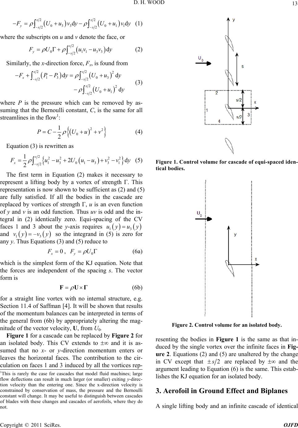 13 D. H. WOOD 22 033 011 22 dd ss yss F Uuvy Uuvy (1) where the subscripts on u and v denote the face, or 2 0113 2d s ys3 F Uuvuv y (2) Similarly, the x-direction force, Fx, is found from 22 2 13 03 22 22 01 2 dd d ss xss s s F PP yUuy Uu y (3) where P is the pressure which can be removed by as- suming that the Bernoulli constant, C, is the same for all streamlines in the flow1: 22 0 1 2 PCU uv (4) Equation (3) is rewritten as 222 22 13013 31 2 12 2 s xsd F uuUuuvv y (5) The first term in Equation (2) makes it necessary to represent a lifting body by a vortex of strength Γ. This representation is now shown to be sufficient as (2) and (5) are fully satisfied. If all the bodies in the cascade are replaced by vortices of strength Γ, u is an even function of y and v is an odd function. Thus uv is odd and the in- tegral in (2) identically zero. Equi-spacing of the CV faces 1 and 3 about the y-axis requires 13 uy uy and so the integrand in (5) is zero for any y. Thus Equations (3) and (5) reduce to 13 –vy vy 0 x F, 0y F U (6a) which is the simplest form of the KJ equation. Note that the forces are independent of the spacing s. The vector form is FUΓ (6b) for a straight line vortex with no internal structure, e.g. Section 11.4 of Saffman [4]. It will be shown that results of the momentum balances can be interpreted in terms of the general from (6b) by appropriately altering the mag- nitude of the vector velocity, U, from U0. Figure 1 for a cascade can be replaced by Figure 2 for an isolated body. This CV extends to ∞ and it is as- sumed that no x- or y-direction momentum enters or leaves the horizontal faces. The contribution to the cir- culation on faces 1 and 3 induced by all the vortices rep- Figure 1. Control volume for cascade of equi-spaced iden- tical bodies. Figure 2. Control volume for an isolated body. resenting the bodies in Figure 1 is the same as that in- duced by the single vortex over the infinite faces in Fig- ure 2. Equations (2) and (5) are unaltered by the change in CV except that 2 s are replaced by ∞ and the argument leading to Equation (6) is the same. This estab- lishes the KJ equation for an isolated body. 1This is rarely the case for cascades that model fluid machines; large flow deflections can result in much larger (or smaller) exiting y-direc- tion velocity than the entering one. Since the x-direction velocity is constrained by conservation of mass, the pressure and the Bernoulli constant will change. It may be useful to distinguish between cascades of blades with these changes and cascades of aerofoils, where they do not. 3. Aerofoil in Ground Effect and Biplanes A single lifting body and an infinite cascade of identical Copyright © 2011 SciRes. OJFD 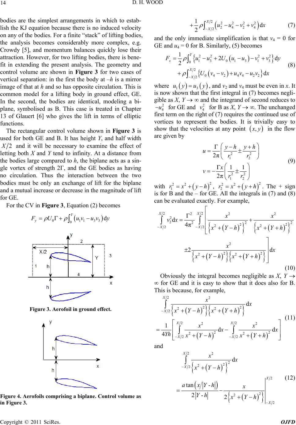 D. H. WOOD 14 bodies are the simplest arrangements in which to estab- lish the KJ equation because there is no induced velocity on any of the bodies. For a finite “stack” of lifting bodies, the analysis becomes considerably more complex, e.g. Crowdy [5], and momentum balances quickly lose their attraction. However, for two lifting bodies, there is bene- fit in extending the present analysis. The geometry and control volume are shown in Figure 3 for two cases of vertical separation: in the first the body at –h is a mirror image of that at h and so has opposite circulation. This is common model for a lifting body in ground effect, GE. In the second, the bodies are identical, modeling a bi- plane, symbolised as B. This case is treated in Chapter 13 of Glauert [6] who gives the lift in terms of elliptic functions. The rectangular control volume shown in Figure 3 is used for both GE and B. It has height Y, and half width 2 X and it will be necessary to examine the effect of letting both X and Y tend to infinity. At a distance from the bodies large compared to h, the biplane acts as a sin- gle vortex of strength 2Γ, and the GE bodies as having no circulation. Thus the interaction between the two bodies must be only an exchange of lift for the biplane and a mutual increase or decrease in the magnitude of lift for GE. For the CV in Figure 3, Equation (2) becomes 01133 0d Y y F Uuvuv y Figure 3. Aerofoil in ground effect. Figure 4. Aerofoils comprising a biplane. Control volume as in Figure 3. 22222 2424 2 1d 2 X Xuuvv x (7) and the only immediate simplification is that v4 = 0 for GE and u4 = 0 for B. Similarly, (5) becomes 22 22 13013 13 0 2 04 24422 2 12d 2 d Y x X X F uuUuuvv y Uv vuv uvx (8) where 13 uy uy, and v2 and v4 must be even in x. It is now shown that the first integral in (7) becomes negli- gible as X, Y ∞ and the integrand of second reduces to 2 4 u for GE and for B as X, Y ∞. The unchanged first term on the right of (7) requires the continued use of vortices to represent the bodies. It is trivially easy to show that the velocities at any point 2 4 v , x y in the flow are given by 22 12 22 12 2π 11 2π yh yh urr x vrr (9) with , . The + sign is for B and the – for GE. All the integrals in (7) and (8) can be evaluated exactly. For example, 2 22 1 rx yh 2 22 2 rx yh 22 22 2 2 222 22 22 22 2 22 22 d4π 2d XX XX xx vx xYhxYh xx xYhxYh 2 (10) Obviously the integral becomes negligible as X, Y ∞ for GE and it is easy to show that it does also for B. This is because, for example, 22 22 22 2 22 22 22 22 22 d 1dd 4 X X XX XX xx xYhxYh xx x x Yh xYhxYh (11) and 22 2 2 2 2 2 2 2 2 d tan - 2- 2 X X X X xx xYh axYh x Yh xYh (12) Copyright © 2011 SciRes. OJFD 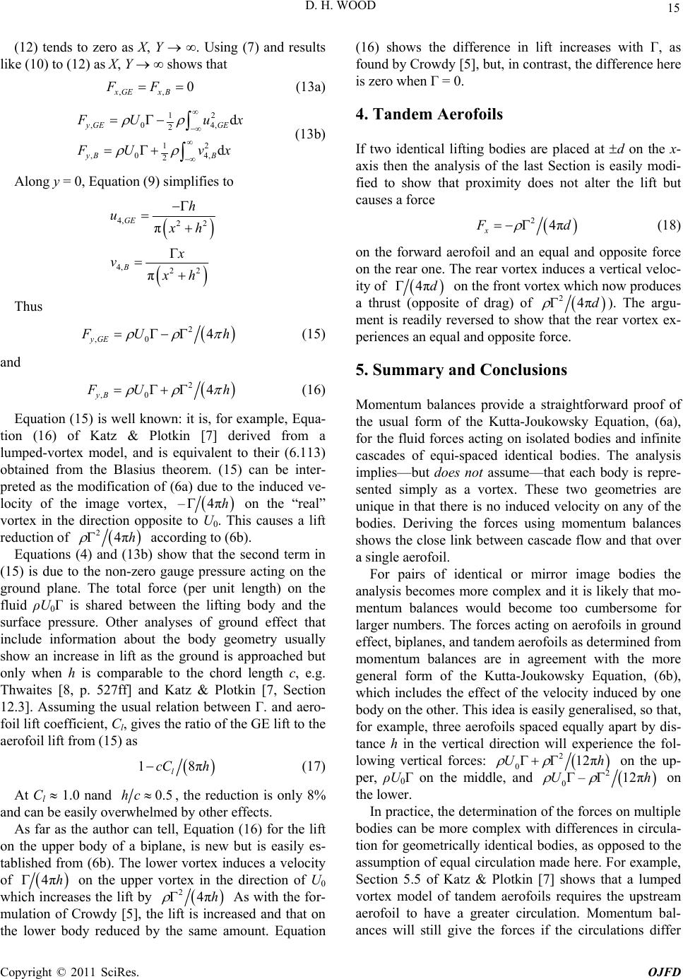 15 D. H. WOOD (12) tends to zero as X, Y ∞. Using (7) and results like (10) to (12) as X, Y ∞ shows that ,, 0 xGE xB FF (13a) 12 ,0 4, 2 12 ,0 4, 2 d d yGE GE yB B F Uux F Uv x (13b) Along y = 0, Equation (9) simplifies to 4, 22 4, 22 π π GE B h u x h x v xh Thus 2 ,0 4 yGE F Uh (15) and 2 ,0 4 yB F Uh (16) Equation (15) is well known: it is, for example, Equa- tion (16) of Katz & Plotkin [7] derived from a lumped-vortex model, and is equivalent to their (6.113) obtained from the Blasius theorem. (15) can be inter- preted as the modification of (6a) due to the induced ve- locity of the image vortex, –4πh on the “real” vortex in the direction opposite to U0. This causes a lift reduction of 24πh according to (6b). Equations (4) and (13b) show that the second term in (15) is due to the non-zero gauge pressure acting on the ground plane. The total force (per unit length) on the fluid ρU0Γ is shared between the lifting body and the surface pressure. Other analyses of ground effect that include information about the body geometry usually show an increase in lift as the ground is approached but only when h is comparable to the chord length c, e.g. Thwaites [8, p. 527ff] and Katz & Plotkin [7, Section 12.3]. Assuming the usual relation between Γ. and aero- foil lift coefficient, Cl, gives the ratio of the GE lift to the aerofoil lift from (15) as 18π l cC h (17) At Cl 1.0 nand 0.5hc, the reduction is only 8% and can be easily overwhelmed by other effects. As far as the author can tell, Equation (16) for the lift on the upper body of a biplane, is new but is easily es- tablished from (6b). The lower vortex induces a velocity of 4πh on the upper vortex in the direction of U0 which increases the lift by 24πh As with the for- mulation of Crowdy [5], the lift is increased and that on the lower body reduced by the same amount. Equation (16) shows the difference in lift increases with Γ, as found by Crowdy [5], but, in contrast, the difference here is zero when Γ = 0. 4. Tandem Aerofoils If two identical lifting bodies are placed at d on the x- axis then the analysis of the last Section is easily modi- fied to show that proximity does not alter the lift but causes a force 24π x F d (18) on the forward aerofoil and an equal and opposite force on the rear one. The rear vortex induces a vertical veloc- ity of 4πd on the front vortex which now produces a thrust (opposite of drag) of 24πd ). The argu- ment is readily reversed to show that the rear vortex ex- periences an equal and opposite force. 5. Summary and Conclusions Momentum balances provide a straightforward proof of the usual form of the Kutta-Joukowsky Equation, (6a), for the fluid forces acting on isolated bodies and infinite cascades of equi-spaced identical bodies. The analysis implies—but does not assume—that each body is repre- sented simply as a vortex. These two geometries are unique in that there is no induced velocity on any of the bodies. Deriving the forces using momentum balances shows the close link between cascade flow and that over a single aerofoil. For pairs of identical or mirror image bodies the analysis becomes more complex and it is likely that mo- mentum balances would become too cumbersome for larger numbers. The forces acting on aerofoils in ground effect, biplanes, and tandem aerofoils as determined from momentum balances are in agreement with the more general form of the Kutta-Joukowsky Equation, (6b), which includes the effect of the velocity induced by one body on the other. This idea is easily generalised, so that, for example, three aerofoils spaced equally apart by dis- tance h in the vertical direction will experience the fol- lowing vertical forces: 2 012πUh on the up- per, ρU0Γ on the middle, and 2 0–12πUh on the lower. In practice, the determination of the forces on multiple bodies can be more complex with differences in circula- tion for geometrically identical bodies, as opposed to the assumption of equal circulation made here. For example, Section 5.5 of Katz & Plotkin [7] shows that a lumped vortex model of tandem aerofoils requires the upstream aerofoil to have a greater circulation. Momentum bal- ances will still give the forces if the circulations differ Copyright © 2011 SciRes. OJFD  D. H. WOOD Copyright © 2011 SciRes. OJFD 16 but they will not fix the magnitudes or the ratios of the circulations. 6. Acknowledgements This work is part of a program of research on wind tur- bines and other forms of renewable energy supported by the National Science and Engineering Research Council and the ENMAX Corporation. 7. References [1] F. M. White, “Fluid Mechanics,” 7th Edition, McGraw- Hill, New York, 2011. [2] R. L. Panton, “Incompressible Flow,” 3rd Edition, John Wiley & Sons, New York, 2005. [3] G. K. Batchelor, “An Introduction to Fluid Dynamics,” Cambridge University Press, Cambridge, 1967. [4] P. G. Saffman, “Vortex Dynamics,” Cambridge Univer- sity Press, Cambridge, 1992. [5] D. Crowdy, “Calculating the Lift on a Finite Stack of Cylindrical Aerofoils,” Proceedings of the Royal Society A, Vol. 462, 2006, pp. 1387-1407. doi:10.1098/rspa.2005.1631 [6] H. Glauert, “The Elements of Aerofoil and Airscrew The- ory,” 2nd Edition, Cambridge University Press, Cam- bridge, 1947. [7] J. Katz and A. Plotkin, “Low Speed Aerodynamics,” 2nd Edition, Cambridge University Press, Cambridge, 2001. [8] B. Thwaites, “Incompressible Aerodynamics,” Clarendon Press, Oxford, 1960. |