

Paper Menu >>
Journal Menu >>
 World Journal of Nano Science and Engineering, 2011, 1, 119-128 doi:10.4236/wjnse.2011.14018 Published Online December 2011 (http://www.SciRP.org/journal/wjnse) Copyright © 2011 SciRes. WJNSE Growth of Boron Nitride Nanotubes Having Large Surface Area Using Mechanothermal Process Sunil K. Singhal1, Avanish K. Srivastava2, Rakesh B. Mathur1 1Physics & Engineering of Carbon, National Physical Laboratory, Council of Scientific & Industrial Research, New Delhi, India 2Ion & Electron Microscopy, National Physical Laboratory, Council of Scientific & Industrial Research, New Delhi, India E-mail: [email protected] Received September 22, 2011; revised October 5, 2011; accepted October 29, 2011 Abstract Nanostructures of boron nitride (BN) including nanotubes, nanofibers and nanosheets having a large surface area are very useful in storing hydrogen and other gases. In the present paper we report the synthesis and characterization of these nanostructures of BN using mechanothermal process. Under this process elemental boron powder is first ball milled to about 50 h in an inert atmosphere and then annealed at 1100˚C - 1250˚C for 6 h in the presence of NH3 gas. By this treatment nanotubes and other nanostructures of BN were synthe- sized. The diameter of BN nanotubes varied from 20 to 50 nm and most of them exhibited spindle or bamboo like morphology. Because of the large surface area, these nanotubes may be explored for a better hydrogen gas storage device as compared to the crystallized nanotubes. The main advantage of this technique is that the nanotubes can be grown in large quantity. A possible growth mechanism towards the evolution of such fascinating nano-objects of boron nitride has been discussed employing high-resolution transmission electron microscopy and photoluminescence. Keywords: Boron Nitride Nanotubes, Mechanothermal Process, Morphology, Photo Luminescence 1. Introduction Boron nitride (BN) nanotubes have received consider- able attention in the recent years due to their outstanding properties such as an electrical insulator with a band gap of 5.9 eV [1], resistance to oxidation at high temperature (above 800˚C) [2] and excellent thermal conductivity [3]. Recently the use of BN nanotubes in the fabrication of polymer based composites for photovoltaic packaging [4] and in the reinforcement of glass to be used as a sealing material in a solid oxide fuel cell [5] is being reported. However, as the synthesis of nanostructure materials ma- tures, there is a growing interest to study the hydrogen storage of new nanostructure materials. Nanostructure ma- terials are one of most promising classes of advanced materials for hydrogen (H2) storage owing to their uni- que chemical, physical, thermodynamic and transport properties as compared to their bulk forms. In this class, carbon nanotubes (CNTs) and nanofibers (NF) are being considered as promising candidates for H2 storage be- cause of their fine powdered morphology and highly porous structure. However, the hydrogen storage capac- ity of boron nitride nanostructures is found to be better than CNTs. The H2 storage capacity of pure multi walled CNTs at room temperature (RT) was measured to be < 0.01 wt% [6] and for single walled CNTs bundles ~0.6 wt% under 10 MPa at RT [7]. It has been found that the nanostructures of BN, namely boron nitride nanotubes, exhibit reproducible hy- drogen uptake of 1.8 - 2.2 wt% at 6 MPa [8] and nano- fibers could absorb 2.9 wt% under 10 MPa at RT [9]. Theoretical calculations by Zhou et al [10] have shown that a well-crystallized, perfect boron nitride nanotubes is infect not a good candidate for H2 storage because of either physical or chemical absorption mechanisms. There- fore, novel nanostructures in BN have been found to be of prime importance, and an increase in surface area for these nanostructure materials may result in an increased H2 storage capacity. Among the various nanostructures of BN, collapsed or surface-modified boron nitride nano- tubes are found to have superb H2 storage capacity [11] due to their highest surface area of these materials. A 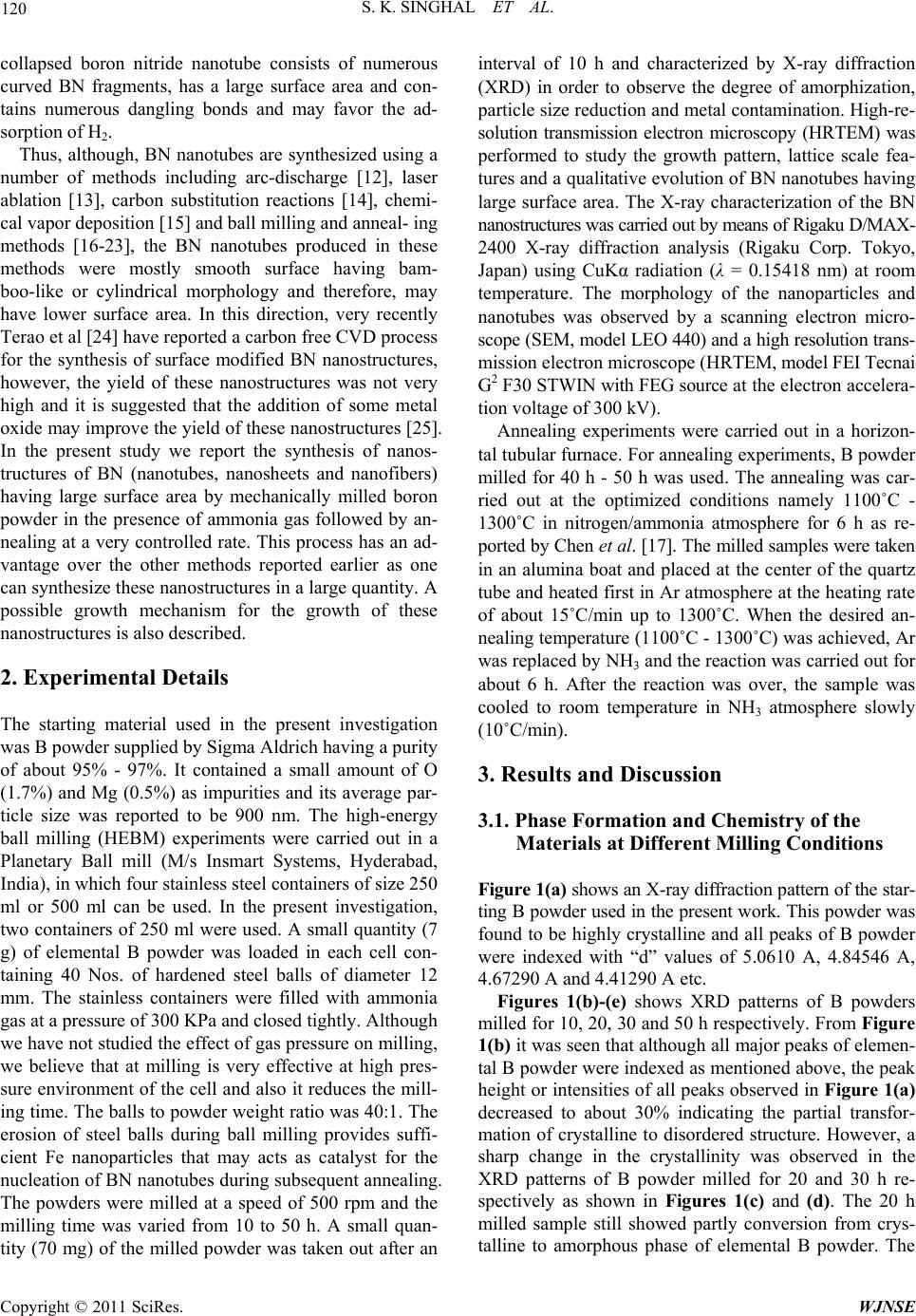 S. K. SINGHAL ET AL. 120 collapsed boron nitride nanotube consists of numerous curved BN fragments, has a large surface area and con- tains numerous dangling bonds and may favor the ad- sorption of H2. Thus, although, BN nanotubes are synthesized using a number of methods including arc-discharge [12], laser ablation [13], carbon substitution reactions [14], chemi- cal vapor deposition [15] and ball milling and anneal- ing methods [16-23], the BN nanotubes produced in these methods were mostly smooth surface having bam- boo-like or cylindrical morphology and therefore, may have lower surface area. In this direction, very recently Terao et al [24] have reported a carbon free CVD process for the synthesis of surface modified BN nanostructures, however, the yield of these nanostructures was not very high and it is suggested that the addition of some metal oxide may improve the yield of these nanostructures [25]. In the present study we report the synthesis of nanos- tructures of BN (nanotubes, nanosheets and nanofibers) having large surface area by mechanically milled boron powder in the presence of ammonia gas followed by an- nealing at a very controlled rate. This process has an ad- vantage over the other methods reported earlier as one can synthesize these nanostructures in a large quantity. A possible growth mechanism for the growth of these nanostructures is also described. 2. Experimental Details The starting material used in the present investigation was B powder supplied by Sigma Aldrich having a purity of about 95% - 97%. It contained a small amount of O (1.7%) and Mg (0.5%) as impurities and its average par- ticle size was reported to be 900 nm. The high-energy ball milling (HEBM) experiments were carried out in a Planetary Ball mill (M/s Insmart Systems, Hyderabad, India), in which four stainless steel containers of size 250 ml or 500 ml can be used. In the present investigation, two containers of 250 ml were used. A small quantity (7 g) of elemental B powder was loaded in each cell con- taining 40 Nos. of hardened steel balls of diameter 12 mm. The stainless containers were filled with ammonia gas at a pressure of 300 KPa and closed tightly. Although we have not studied the effect of gas pressure on milling, we believe that at milling is very effective at high pres- sure environment of the cell and also it reduces the mill- ing time. The balls to powder weight ratio was 40:1. The erosion of steel balls during ball milling provides suffi- cient Fe nanoparticles that may acts as catalyst for the nucleation of BN nanotubes during subsequent annealing. The powders were milled at a speed of 500 rpm and the milling time was varied from 10 to 50 h. A small quan- tity (70 mg) of the milled powder was taken out after an interval of 10 h and characterized by X-ray diffraction (XRD) in order to observe the degree of amorphization, particle size reduction and metal contamination. High-re- solution transmission electron microscopy (HRTEM) was performed to study the growth pattern, lattice scale fea- tures and a qualitative evolution of BN nanotubes having large surface area. The X-ray characterization of the BN nanostructures was carried out by means of Rigaku D/MAX- 2400 X-ray diffraction analysis (Rigaku Corp. Tokyo, Japan) using CuKα radiation (λ = 0.15418 nm) at room temperature. The morphology of the nanoparticles and nanotubes was observed by a scanning electron micro- scope (SEM, model LEO 440) and a high resolution trans- mission electron microscope (HRTEM, model FEI Tecnai G2 F30 STWIN with FEG source at the electron accelera- tion voltage of 300 kV). Annealing experiments were carried out in a horizon- tal tubular furnace. For annealing experiments, B powder milled for 40 h - 50 h was used. The annealing was car- ried out at the optimized conditions namely 1100˚C - 1300˚C in nitrogen/ammonia atmosphere for 6 h as re- ported by Chen et al. [17]. The milled samples were taken in an alumina boat and placed at the center of the quartz tube and heated first in Ar atmosphere at the heating rate of about 15˚C/min up to 1300˚C. When the desired an- nealing temperature (1100˚C - 1300˚C) was achieved, Ar was replaced by NH3 and the reaction was carried out for about 6 h. After the reaction was over, the sample was cooled to room temperature in NH3 atmosphere slowly (10˚C/min). 3. Results and Discussion 3.1. Phase Formation and Chemistry of the Materials at Different Milling Conditions Figure 1(a) shows an X-ray diffraction pattern of the star- ting B powder used in the present work. This powder was found to be highly crystalline and all peaks of B powder were indexed with “d” values of 5.0610 A, 4.84546 A, 4.67290 A and 4.41290 A etc. Figures 1(b)-(e) shows XRD patterns of B powders milled for 10, 20, 30 and 50 h respectively. From Figure 1(b) it was seen that although all major peaks of elemen- tal B powder were indexed as mentioned above, the peak height or intensities of all peaks observed in Figure 1(a) decreased to about 30% indicating the partial transfor- mation of crystalline to disordered structure. However, a sharp change in the crystallinity was observed in the XRD patterns of B powder milled for 20 and 30 h re- spectively as shown in Figures 1(c) and (d). The 20 h milled sample still showed partly conversion from crys- talline to amorphous phase of elemental B powder. The Copyright © 2011 SciRes. WJNSE 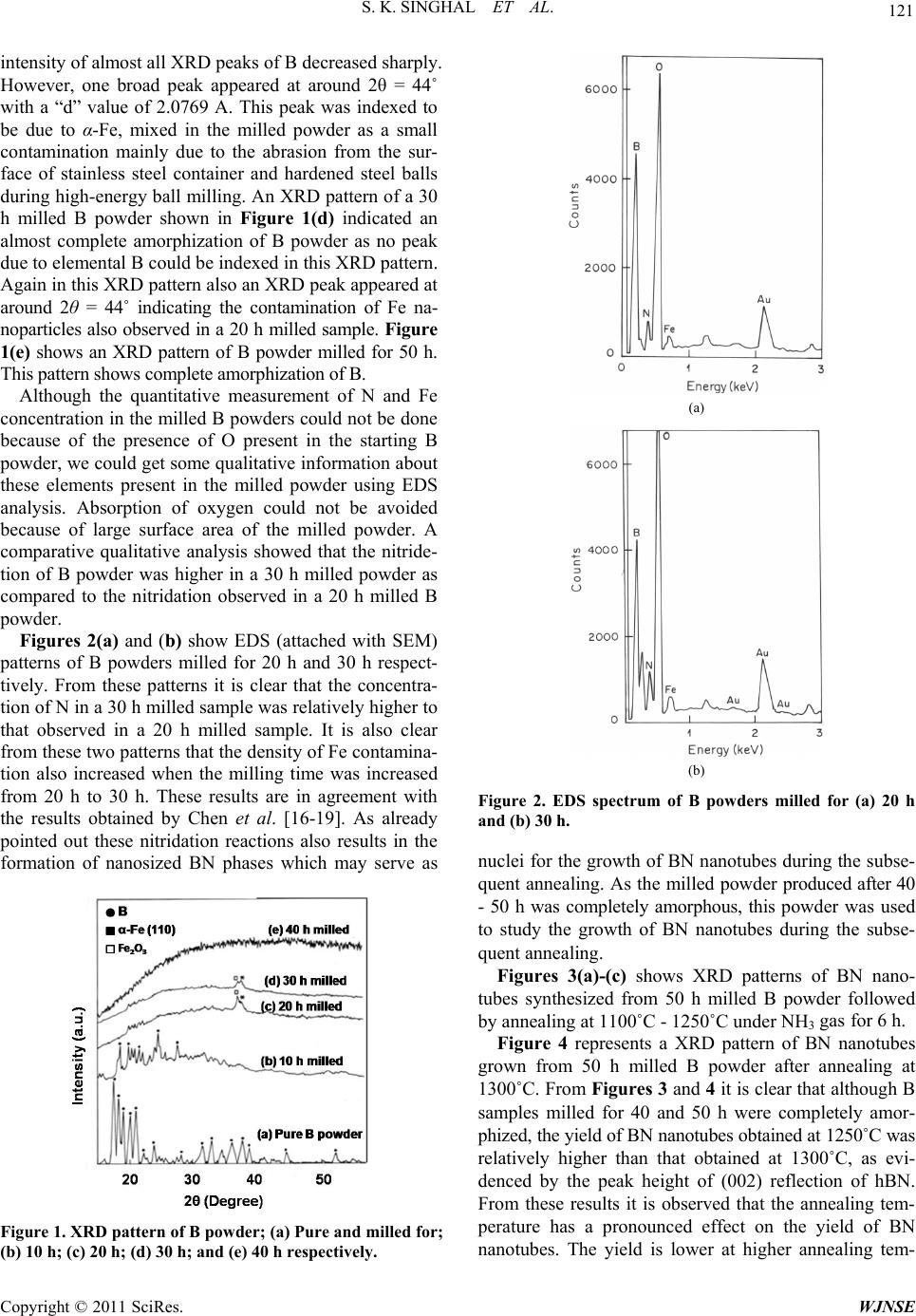 121 S. K. SINGHAL ET AL. intensity of almost all XRD peaks of B decreased sharply. However, one broad peak appeared at around 2θ = 44˚ with a “d” value of 2.0769 A. This peak was indexed to be due to α-Fe, mixed in the milled powder as a small contamination mainly due to the abrasion from the sur- face of stainless steel container and hardened steel balls during high-energy ball milling. An XRD pattern of a 30 h milled B powder shown in Figure 1(d) indicated an almost complete amorphization of B powder as no peak due to elemental B could be indexed in this XRD pattern. Again in this XRD pattern also an XRD peak appeared at around 2θ = 44˚ indicating the contamination of Fe na- noparticles also observed in a 20 h milled sample. Figure 1(e) shows an XRD pattern of B powder milled for 50 h. This pattern shows complete amorphization of B. Although the quantitative measurement of N and Fe concentration in the milled B powders could not be done because of the presence of O present in the starting B powder, we could get some qualitative information about these elements present in the milled powder using EDS analysis. Absorption of oxygen could not be avoided because of large surface area of the milled powder. A comparative qualitative analysis showed that the nitride- tion of B powder was higher in a 30 h milled powder as compared to the nitridation observed in a 20 h milled B powder. Figures 2(a) and (b) show EDS (attached with SEM) patterns of B powders milled for 20 h and 30 h respect- tively. From these patterns it is clear that the concentra- tion of N in a 30 h milled sample was relatively higher to that observed in a 20 h milled sample. It is also clear from these two patterns that the density of Fe contamina- tion also increased when the milling time was increased from 20 h to 30 h. These results are in agreement with the results obtained by Chen et al. [16-19]. As already pointed out these nitridation reactions also results in the formation of nanosized BN phases which may serve as Figure 1. XRD pattern of B powder; (a) Pure and milled for; (b) 10 h; (c) 20 h; (d) 30 h; and (e) 40 h respectively. (a) (b) Figure 2. EDS spectrum of B powders milled for (a) 20 h and (b) 30 h. nuclei for the growth of BN nanotubes during the subse- quent annealing. As the milled powder produced after 40 - 50 h was completely amorphous, this powder was used to study the growth of BN nanotubes during the subse- quent annealing. Figures 3(a)-(c) shows XRD patterns of BN nano- tubes synthesized from 50 h milled B powder followed by annealing at 1100˚C - 1250˚C under NH3 gas for 6 h. Figure 4 represents a XRD pattern of BN nanotubes grown from 50 h milled B powder after annealing at 1300˚C. From Figures 3 and 4 it is clear that although B samples milled for 40 and 50 h were completely amor- phized, the yield of BN nanotubes obtained at 1250˚C was relatively higher than that obtained at 1300˚C, as evi- denced by the peak height of (002) reflection of hBN. From these results it is observed that the annealing tem- perature has a pronounced effect on the yield of BN nanotubes. The yield is lower at higher annealing tem- Copyright © 2011 SciRes. WJNSE  S. K. SINGHAL ET AL. Copyright © 2011 SciRes. WJNSE 122 perature (1300˚C and higher). The growth of BN nano- tubes is presumed to takes place via the dissolution of nanosized B/BN species in the catalyst nanoparticles of Fe. The catalyst (Fe-nanoparticles) should be in a quasi- liquid state in order to dissolve maximum concentration of B/BN phased to a state of supersaturation. BN nano- tubes are grown from the supersaturated solution layer by layer along the (002) planes. It was also found by Yu et al. [26] that a much higher annealing temperature (T > 1300˚C) is not favored for the growth of BN nanotubes as at this temperature, the catalyst nanoparticles (Fe) would be in the liquid state and they may merged together to form large size Fe crystals and then may impede the growth of BN nanotubes. Also the B particles may react directly with N to form BN particles instead of nanotubes and used up the B source. ticles (Cr, Ni etc.) were introduced into the milled B po- wder during ball milling from the surface of stainless steel balls and container. The milling contamination is almost unavoidable by the mechanical milling process, especially under high milling intensity, and this conta- mination increases with milling time as observed by the increase in peak intensity of Fe shown in XRD patterns of the milled B powders. In general, such milling con- tamination is undesirable but, in the present case (Fe, Ni, Cr from the stainless steel container) have been found to have positive catalytic role in promoting BN nanotube At temperatures lower than 1100˚C, the low diffusion rate of B and N in Fe would slow down the precipitation rate of BN layers (i.e. the growth rate of BN nanotubes). Figure 5 shows an XRD pattern of the products pro- duced from un-milled B powder and annealed at 1300˚C in the presence of ammonia gas. No BN nanotube growth was found from this powder under the same annealing conditions that produced nanotubes from the milled sam- ples. This suggests that the milling process has an essen- tial role to play in BN nanotube formation during subse- quent annealing, which appears to be associated with the creation of suitable nucleation sites for nanotube growth. Under the high milling intensity used in the present work, elemental B was transformed into disordered amorphous phase. The amorphous phase is metastable and recrystal- lized during the annealing process. Figure 3. XRD patterns of BN nanotubes synthesized from B powder milled for 50 h and annealed at (a) 1100˚C; (b) 1150˚C and (c) 1250˚C under NH3 gas for 6 h. It has been observed that Fe and other metal nanopar- Figure 4. XRD pattern pf BN nanotubes synthesized at 1300˚C. 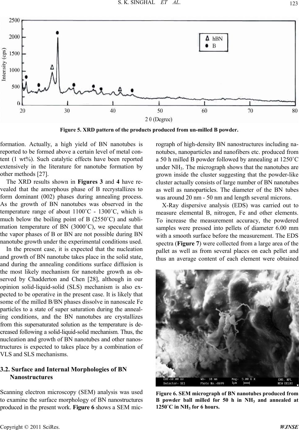 123 S. K. SINGHAL ET AL. Figure 5. XRD pattern of the products produced from un-milled B powder. formation. Actually, a high yield of BN nanotubes is reported to be formed above a certain level of metal con- tent (1 wt%). Such catalytic effects have been reported extensively in the literature for nanotube formation by other methods [27]. The XRD results shown in Figures 3 and 4 have re- vealed that the amorphous phase of B recrystallizes to form dominant (002) phases during annealing process. As the growth of BN nanotubes was observed in the temperature range of about 1100˚C - 1300˚C, which is much below the boiling point of B (2550˚C) and subli- mation temperature of BN (3000˚C), we speculate that the vapor phases of B or BN are not possible during BN nanotube growth under the experimental conditions used. In the present case, it is expected that the nucleation and growth of BN nanotube takes place in the solid state, and during the annealing conditions surface diffusion is the most likely mechanism for nanotube growth as ob- served by Chadderton and Chen [28], although in our opinion solid-liquid-solid (SLS) mechanism is also ex- pected to be operative in the present case. It is likely that some of the milled B/BN phases dissolve in nanoscale Fe particles to a state of super saturation during the anneal- ing conditions, and the BN nanotubes are crystallizes from this supersaturated solution as the temperature is de- creased following a solid-liquid-solid mechanism. Thus, the nucleation and growth of BN nanotubes and other nanos- tructures is expected to takes place by a combination of VLS and SLS mechanisms. 3.2. Surface and Internal Morphologies of BN Nanostructures Scanning electron microscopy (SEM) analysis was used to examine the surface morphology of BN nanostructures produced in the present work. Figure 6 shows a SEM mic- rograph of high-density BN nanostructures including na- notubes, nanoparticles and nanofibers etc. produced from a 50 h milled B powder followed by annealing at 1250˚C under NH3. The micrograph shows that the nanotubes are grown inside the cluster suggesting that the powder-like cluster actually consists of large number of BN nanotubes as well as nanoparticles. The diameter of the BN tubes was around 20 nm - 50 nm and length several microns. X-Ray dispersive analysis (EDS) was carried out to measure elemental B, nitrogen, Fe and other elements. To increase the measurement accuracy, the powdered samples were pressed into pellets of diameter 6.00 mm with a smooth surface before the measurement. The EDS spectra (Figure 7) were collected from a large area of the pallet as well as from several places on each pellet and thus an average content of each element were obtained Figure 6. SEM micrograph of BN nanotubes produc ed from B powder ball milled for 50 h in NH3 and annealed at 1250˚C in NH3 for 6 hours. Copyright © 2011 SciRes. WJNSE 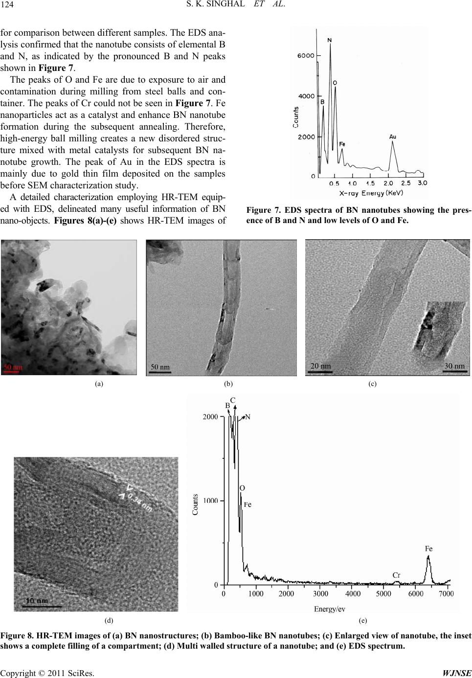 S. K. SINGHAL ET AL. 124 for comparison between different samples. The EDS ana- lysis confirmed that the nanotube consists of elemental B and N, as indicated by the pronounced B and N peaks shown in Figure 7. The peaks of O and Fe are due to exposure to air and contamination during milling from steel balls and con- tainer. The peaks of Cr could not be seen in Figure 7. Fe nanoparticles act as a catalyst and enhance BN nanotube formation during the subsequent annealing. Therefore, high-energy ball milling creates a new disordered struc- ture mixed with metal catalysts for subsequent BN na- notube growth. The peak of Au in the EDS spectra is mainly due to gold thin film deposited on the samples before SEM characterization study. A detailed characterization employing HR-TEM equip- ed with EDS, delineated many useful information of BN nano-objects. Figures 8(a)-(e) shows HR-TEM images of Figure 7. EDS spectra of BN nanotubes showing the pres- ence of B and N and low levels of O and Fe. (a) (b) (c) (d) (e) Figure 8. HR-TEM images of (a) BN nanostructures; (b) Bamboo-like BN nanotubes; (c) Enlarged view of nanotube, the inset shows a complete filling of a compartment; (d) Multi walled structure of a nanotube; and (e) EDS spectrum. Copyright © 2011 SciRes. WJNSE 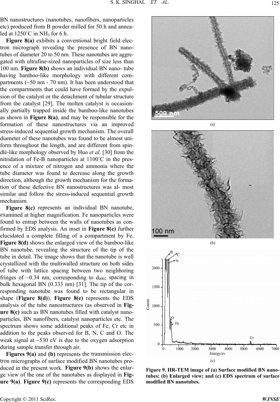 S. K. SINGHAL ET AL. 125 entional bright field elec- tro ) represents an individual BN nanotube, ex he transmission elec- tro ure 9(a). Figure 9(c) reprnts the corresponding EDS N nanostructures (nanotubes, nanofibers, nanoparticles B etc) produced from B powder milled for 50 h and annea- led at 1250˚C in NH3 for 6 h. Figure 8(a) exhibits a conv n micrograph revealing the presence of BN nano- tubes of diameter 20 to 50 nm. These nanotubes are aggre- gated with ultrafine-sized nanoparticles of size less than 100 nm. Figure 8(b) shows an individual BN nano- tube having bamboo-like morphology with different com- partments (~50 nm - 70 nm). It has been understood that the compartments that could have formed by the expul- sion of the catalyst or the detachment of tubular structure from the catalyst [29]. The molten catalyst is occasion- ally partially trapped inside the bamboo-like nanotubes as shown in Figure 8(a), and may be responsible for the formation of these nanostructures via an improved stress-induced sequential growth mechanism. The overall diameter of these nanotubes was found to be almost uni- form throughout the length, and are different from spin- dle-like morphology observed by Huo et al. [30] from the nitridation of Fe-B nanoparticles at 1100˚C in the pres- ence of a mixture of nitrogen and ammonia where the tube diameter was found to decrease along the growth direction, although the growth mechanism for the forma- tion of these defective BN nanostructures was al- most similar and follow the stress-induced sequential growth mechanism. Figure 8(c amined at higher magnification. Fe nanoparticles were found to entrap between the walls of nanotubes as con- firmed by EDS analysis. An inset in Figure 8(c) further elucidated a complete filling of a compartment by Fe. Figure 8(d) shows the enlarged view of the bamboo-like BN nanotube, revealing the structure of the tip of the tube in detail. The image shows that the nanotube is well crystallized with the multiwalled structure on both sides of tube with lattice spacing between two neighboring fringes of ~0.34 nm, corresponding to d0002 spacing in bulk hexagonal BN (0.333 nm) [31]. The tip of the cor- responding nanotube was found to be rectangular in shape (Figure 8(d)). Figure 8(e) represents the EDS analysis of the tube nanostructures (as observed in Fig- ure 8(c) such as BN nanotubes filled with catalyst nano- particles, BN nanofibers, catalyst nanoparticles etc. The spectrum shows some additional peaks of Fe, Cr etc in addition to the peaks observed for B, N, C and O. The weak signal at ~530 eV is due to the oxygen adsorption during sample transfer through air. Figures 9(a) an d (b) represents t n micrographs of surface modified BN nanotubes pro- duced in the present work. Figure 9(b) shows the enlar- ge view of the one of the nanotubes as displayed in Fig- ese (a) (b) (c) Figure 9. HR-TEM image of (a) Surface modified BN nano- tubes; (b) Enlarged view; and (c) EDS spectrum of surface modified BN nanotubes. Copyright © 2011 SciRes. WJNSE 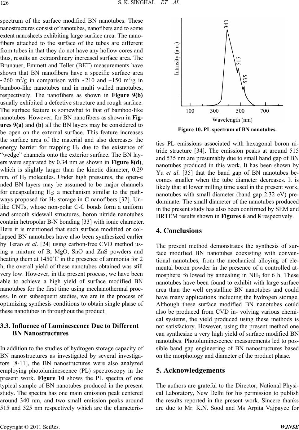 S. K. SINGHAL ET AL. 126 Bigated by several investiga- spectrum of the surface modified BN nanotubes. These nanostructures consist of nanotubes, nanofibers and to some extent nanosheets exhibiting large surface area. The nano- fibers attached to the surface of the tubes are different from tubes in that they do not have any hollow cores and thus, results an extraordinary increased surface area. The Brunauer, Emmett and Teller (BET) measurements have shown that BN nanofibers have a specific surface area ~260 m2/g in comparison with ~210 and ~150 m2/g in bamboo-like nanotubes and in multi walled nanotubes, respectively. The nanofibers as shown in Figure 9(b) usually exhibited a defective structure and rough surface. The surface feature is somewhat to that of bamboo-like nanotubes. However, for BN nanofibers as shown in Fig- ures 9(a) and (b) all the BN layers may be considered to be open on the external surface. This feature increases the surface area of the material and also decreases the energy barrier for trapping H2 due to the existence of “wedge” channels onto the exterior surface. The BN lay- ers were separated by 0.34 nm as shown in Figure 8(d), which is slightly larger than the kinetic diameter, 0.29 nm, of H2 molecules. Under high pressures, the open-e nded BN layers may be assumed to be major channels for encapsulating H2; a mechanism similar to the path- ways proposed for H2 storage in C nanofibers [32]. Un- like CNTs, whose non-polar C-C bonds form a uniform and smooth sidewall structures, boron nitride nanotubes contain hetropolar B-N bonding [33] with ionic character. Here it is mentioned that such surface modified or col- lapsed BN nanotubes have also been synthesized earlier by Terao et al. [24] using carbon-free CVD method us- ing a mixture of B, MgO, SnO and ZnS powders and heating them at 1450˚C in the presence of ammonia for 2 h, the overall yield of these nanotubes obtained was still very low. However, in the present process, we have been able to achieve a high yield of surface modified BN nanotubes for the first time using mechanothermal proc- ess. In our subsequent studies, we are in the process of optimizing synthesis conditions to obtain single phase of these nanotubes in throughout the product. 3.3. Influence of Luminescence Due to Different BN Nanostructures In addition to the studies of hydrogen storage capacity of nanostructures as investN tors [8-11], the BN nanostructures were also analyzed employing photoluminescence (PL) spectroscopy in the present work. Figure 10 shows the PL spectra of one typical sample of BN nanotubes produced in the present study. The spectra has one main emission peak centered around 340 nm, and two small emission peaks around 515 and 525 nm respectively which are the characteris- Figure 10. PL spectrum of BN nanotubes. tics PL emissions associated with hexagonal bori- tride strnd 515 nd 535 nm are presumably due to small band gap of BN The present method demonstrates the synthesis of sur- nanotubes coexisting with conven- tional nanotubes, from the mechanical alloying of ele- The authors are grateful to the Director, National Physi- or his permission to publish thresults reported in the present work. Sincere thanks on n ucture [34]. The emission peaks at arou a nanotubes produced in this work. It has been shown by Yu et al. [35] that the band gap of BN nanotubes be- comes smaller when the tube diameter decreases. It is likely that at lower milling time used in the present work, nanotubes with small diameter (band gap 2.32 eV) pre- dominate. The small diameter of the nanotubes produced in the present study has also been confirmed by SEM and HRTEM results shown in Figures 6 and 8 respectively. 4. Conclusions face modified BN mental boron powder in the presence of a controlled at- mosphere followed by annealing in NH3 for 6 h. These nanotubes have been found to exhibit with large surface area than the well crystalline BN nanotubes and could have many applications including the hydrogen storage. Although these surface modified BN nanotubes could also be produced from CVD in- volving various chemi- cal systems, the yield produced using these methods is not satisfactory. However, using the present method one can synthesize a very high yield of surface modified BN nanotubes. Photoluminescence measurements led to pos- sible band gap engineering of BN nanostructures based on the morphology and diameter of the product phase. 5. Acknowledgements cal Laboratory, New Delhi f e are due to Mr. K.N. Sood and Ms Arpita Vajpayee for Copyright © 2011 SciRes. WJNSE  S. K. SINGHAL ET AL. 127 ] C. H. Lee, J. Wang, V. K. Kayatsha, J. Y. Huang and Y. of Boron Nitride Nanotubes Deposition,” Nanotechnol- their help in SEM and XRD characterization of BN na- notubes produced in this work. 6. References [1 K. Yap, “Effective Growth by Thermal Chemical Vapor ogy, Vol. 19, No. 45, 2008, pp. 455605. doi:10.1088/0957-4484/19/45/455605 [2] Y. Chen, J. Zou, S. J. Campbell and G. L. Caer, “Boron Nitride Nanotubes: Pronounced Resistance Applied Physics Letters, Vol. 84, No. 1 to Oxidation,” 3, 2004, pp. 2430- 2433. doi:10.1063/1.1667278 [3] C. W. Chang, W.-Q. Han and A. Zettl, “Thermal Con- ductivity of B-C-N and BN Nanotubes,” Applied Physics Letters, Vol. 86, No. 17, 2005, pp. 173102-173104. doi:10.1063/1.1914963 [4] J. Ravichandran, A. G. Manoj, J. Liu, I. Manna and D. L. Carrol, “A Novel Polymer Nanotube Composite for Ph voltaic Packaging Appl oto- ications,” Nanotechnology, Vol. 19, No. 8, 2008, p. 085712. doi:10.1088/0957-4484/19/8/085712 [5] N. P. Bansal, J. B. Hurst and S. R. Choi, “Boron Nitride Nanotubes-Reinforced Glass American Ceramic Society, Vol. 89 Composites” Journal of th , No. 1, 2006, pp. e 388-389. doi:10.1111/j.1551-2916.2005.00701.x [6] S. S. Han and H. M. Lee, “Adsorption Properties of Hy- drogen on (10,0) Single-Walled Carbon Nanotube through Density Functional Theory,” Carbon, Vol. 42, No. 11, 2004, pp. 2169-2177. doi:10.1016/j.carbon.2004.04.025 [7] J. Lawrence and G. Xu, “High Pressure Saturation of Hy- drogen Stored by Single-Wall Carbon Nanotubes,” Ap- plied Physics Letters, Vol. 84, No. 6, 2004, pp. 918-920. doi:10.1063/1.1646728 [8] S. H. Lim, J. Luo, W. Li and J. Lin, “Synthesis of Boron Nitride Nanotubes and Its Hydrogen Uptake,” Catalysis Today, Vo. 120, No. 3-4, 2007, pp. 346-350. doi:10.1016/j.cattod.2006.09.016 [9] R. Ma, Y. Bnado, T. Sato, D. Golberg, H. Zhu, C. Xu and D. Wu, “Synthesis of Boron Nitride Nanofibers surement of Their Hydrogen Uptake C and Mea- apacity,” Applied Physics Letters, Vol. 81, No. 27, 2002, pp. 5225-5257. doi:10.1063/1.1534415 [10] Z. Zhou, J. Zhao, Z. Chen, X. Gao, T. Yan, B. Wen, P. Van and R. Schlayer, “ Comparative Study of Hydrogen Adsorption on Carbon and BN Nanotubes,” Journal of Physical Chemistry B, Vol. 110, No. 27, 2006, pp. 13363- 13369. doi:10.1021/jp0622740 [11] C. C. Tang, Y. Bando, X. Ding, S. Qi and D. Golberg, “Catalyzed Collapse and Enhanced Hydrogen Storage of BN Nanotubes,” Journal of the American Chemical Society, Vol. 124, No. 49, 2002, pp. 14550-14551. doi:10.1021/ja028051e [12] N. G. Chopra, R. J. Luyken, K. Cherrey, V. H. Crespi, M. L. Cohen, S. G. Louie and A. Zettl, “Boron N tubes,” Science, Vol. 269 itride Nano- , No. 5226, 1995, pp. 966-967. doi:10.1126/science.269.5226.966 [13] D. Golberg, Y. Bando, M. Eremets, K .Takemura, K. Ku- rashima and H. Yusa, “ Nanotubes in Boron Nitride La- ser Heated at High Pressure,” Applied Physics Letters, Vol. 69, No. 14, 1996, pp. 2045-2047. doi:10.1063/1.116874 [14] D. Golberg, W. Han, Y. Bando, L. Bourgeois, K. Kura- shima and T. Sato, “Fine Structure of Bo tubes Produced from C rn Nitride Nano- arbon Nanotubes by a Substitution Reaction,” Journal of Applied Physics, Vol. 86, No. 4, 1999, pp. 2364-2366. doi:10.1063/1.371058 [15] C. C. Tang, Y. Bando, T. Sato and K. Kurashima, “A Novel Precursor for the Synthesis of Pure Boron Nitride Nanotubes,” Chemical Communications, No. 12, 2002, pp. 1290-1291. doi:10.1039/B202177C [16] Y. Chen, J. F. Gerald, J. S. Williams and S. Bulcock, “Synthesis of Boron Nitride Nanotubes at Low Tempera- tures Using Reactive Ball Milling,” Chemical Physics Letters, Vol. 299, No. 3-4, 1999, pp. 260-264. doi:10.1016/S0009-2614(98)01252-4 [17] Y. Chen, L. T. Chadderton, J. F. Gerald, J. S. Williams, “A Solid-State Process for the Formation Boro Nanotubes,” Applied Physics Letters, Vol. 74 n Nitride , No. 20, 1999, pp. 2960-2962. doi:10.1063/1.123979 [18] Y. Chen, J. F. Gerald, J. S. Williams and P. Willis, “Me- chanochemical Synthesis of Boron Nitride Nanotubes,” Journal of Metastable and Nanocrystalline Materials, Vol. 2-6, 1999, pp. 173-187. doi:10.4028/www.scientific.net/JMNM.2-6.173 [19] Y. Chen, M. Conway J. S. Williams and J. Zou, “ Large- Quantity Production of High-Y tubes,” Journal of Materials Research, Vol. 17 ield Boron Nitride Nano- , No. 8, 2002, pp. 1896-1899. doi:10.1557/JMR.2002.0281 [20] S. K. Singhal, A. K. Srivastva, R. P. Pant, S. K. Halder, B. P. Singh and A. K. Gupta, “Synthesis of Boron Nitride Nanotubes Employing Mechanothermal Process and Its Characterization,” Journal of Materials Science, Vol. 43, No. 15, 2008, pp. 5243-5250. doi:10.1007/s10853-008-2770-3 [21] J. F. Gerald, Y. Chen and M. J. Conway, “Nanotube Growth during Annealing of Mechanic plied Physics A, Vol. 76, No. 1, 2003, pp ally Milled Boron,” Ap- .107-110. doi:10.1007/s00339-002-1441-5 [22] S. Y. Bae, H. W. Seo, J. Park, Y. S. Choi, J. C. Park and S. Y. Lee, “Boron Nitride Nanotubes Synthesized in Temperature Range 1000˚C - 1200 The ˚C,” Chemical Physics Letters, Vol. 374, No. 5-6, 2003, pp. 534-541. doi:10.1016/S0009-2614(03)00745-0 [23] F. Q. Ji, C. B. Cao, H. Xu and Z. G. Yang, “Mechano- synthesis of Boron Nitride Nanotubes,” Chines of Chemical Engineering, Vol. 14, No e Journal . 3, 2006, pp. 389- 393. doi:10.1016/S1004-9541(06)60088-8 [24] T. Terao, Y. Bando, M. Mitome, K. Kurashima, C. Y. Zhi, C. C. Tang and D. Golberg, “Effective Synthesis of Sur- face-Modified Boron Nitride Nanotubes and Related Nano- structures and Their Hydrogen Uptake,” Physica E, Vol. Copyright © 2011 SciRes. WJNSE  S. K. SINGHAL ET AL. Copyright © 2011 SciRes. WJNSE 128 40, No. 7, 2008, pp. 2551-2555. doi:10.1016/j.physe.2007.10.014. [25] C. Y. Zhi, Y. Bando, C. C. Tang and D. Golberg, “Effec- tive Precursor for High Yield Synthesis of Pure BN Na- notubes,” Solid State Communicat 2005, pp. 67-70. ions, Vol. 135, No. 1-2, se.2007.10.014doi:10.1016/j.phy . [26] J. Yu, Y. Chen, R. G. Elliman and M. Petravic,” Isotopi- cally Enriched 10BN Nanotubes,” Advanced Materials, Vol. 18, No. 16, 2006, pp. 2157-2160. doi:10.1002/adma.200600231 [27] G. J. Tibbetts, “Why Are Carbon Filaments Tubular,” Jour- nal of Crystal Growth, Vol. 66, No. 3, 1984, pp. 632-638. doi:10.1016/0022-0248(84)90163-5 [28] L. T. Chadderton and Y. Chen, “Nanotube Growth by Surface Diffusion,” Physics Letters A, Vol. 263, No. 4-6, 1999, pp. 401-405. doi:10.1016/S0375-9601(99)00731-8 [29] L. T. Chadderton and Y. Chen, “A Model for the Growth Bamboo and Skeletal Nanotubes: Catalytic Capillarity,” Journal of Crystal Growth, Vol. 240, No. 1-2, 2002, pp. 164-169. doi:10.1016/S0022-0248(02)00855-2 [30] H. F. Huo, Z. Hu, J. J. Fu, H. Xu, X. Z. Wang, Y. Chen and Y. N. Lu, “Microstructure and Growth Model of Pe- riod Spindle-Unit BN Nanotubes by Nitriding Fe-B Na- noparticles with Nitrogen/Ammonia Mixture,” Journal of Physical Chemistry B, Vol. 107, No. 41, 2003, pp. 11316- 11320. doi:10.1021/jp035375w [31] K. F. Hou, Z. Hu, F. Chen, J. J. Fu, Y. Chen, B. H. Liu, J. Ding, Z. L. Dong and T. White, “Synthesis of Boron Ni- tride Nanowires,” Applied Physics Letters, Vol. 80, No. 19, 2002, pp. 3611-3613. doi:10.1063/1.1479213 [32] A. Chambers, C. Park, R. T. K. Baker and N. M. Rodri- guez, “Hydrogen storage in Graphite Nanofibers,” Jour- nal of Physical Chemistry B, Vol. 102, No. 22, 1998, pp. 4253-4256. doi:10.1021/jp980114l. [33] S. Jhi and Y. Kwon, “Hydrogen Adsorption on Boron Ni- tride Nanotubes: A Path to Room-Temperature Hydrogen Storage,” Physical Review B, Vol. 69, No. 24, 2004, p. 245407. doi:10.1103/Phys Rev B.69.245407 [34] J. Yu, Y. Chen, R. Wuhrer, Z. Liu and S. P. Ranger, “In- situ Formation of BN Nanotubes during Nitriding Reac- tions,” Chemistry of Materials, Vol. 17, No. 20, 2005, pp. 5172-5176. doi:10.1021/cm050966f [35] J. Yu, D. Yu, Y. Chen, H. Chen, M. Y. Lin, B. M. Cheng, J. Li and W. Duan, “Narrowed Bandgaps and Stronger Excitonic Effects from Small Boron Nitride Nanotubes,” Chemical Physics Letters, Vol. 476, No. 4-6, 2009, pp. 240-243. doi:10.1016/j.cplett.2009.06.012 |