

Paper Menu >>
Journal Menu >>
 Optics and Photonics Journal, 2011, 1, 172-178 doi:10.4236/opj.2011.14028 Published Online December 2011 (http://www.SciRP.org/journal/opj) Copyright © 2011 SciRes. OPJ Transmission Characteristics of Tuneable Optical Filters Using Optical Ring Resonator with PCF Resonance Loop Kazhal Shalmashi1, Faramarz E. Seraji2, Mansur Rezaei Mersagh1 1Physics Group, Islamic Azad University, Tehran Shomal Branch, Tehran, Iran 2Optical Communication Group, Iran Telecom Research Center, Tehran, Iran E-mail: [email protected] Received August 30, 2011; revised September 27, 2011; accepted October 11, 2011 Abstract A theoretical analysis of a tuneable optical filter is presented by proposing an optical ring resonator (ORR) using photonic crystal fiber (PCF) as the resonance loop. The influences of the characteristic parameters of the PCF on the filter response have been analyzed under steady-state condition of the ORR. It is shown that the tuneability of the filter is mainly achieved by changing the modulation frequency of the light signal ap- plied to the resonator. The analyses have shown that the sharpness and the depth of the filter response are controlled by parameters such as amplitude modulation index of applied field, the coupling coefficient of the ORR, and hole-spacing and air-filling ratio of the PCF, respectively. When transmission coefficient of the loop approaches the coupling coefficient, the filter response enhances sharply with PCF parameters. The depth and the full-width half-maximum (FWHM) of the response strongly depends on the number of field circulations in the resonator loop. With the proposed tuneability scheme for optical filter, we achieved an FWHM of 1.55 nm. The obtained results may be utilized in designing optical add/drop filters used in WDM communication systems. Keywords: Optical Ring Resonator, Photonic Crystal Fiber, Tuneable Optical Filter, Optical Fiber 1. Introduction In last two decades, optical ring resonators (ORR) with different configurations, based on fiber and wave-guides [1-4], have been analyzed for different applications such as polarization sensing [5], bio-sensing [6], optical filters [7-9], dispersion compensation [10,11], optical triggering and optical integration/differentiation [2], optical bista- bility [12,13], add/drop multiplexer [14], optical swit- ching [15-18], and various other applications [19-21]. In the early works, steady state [2,22] and dynamic resp- onses of ORR built on fiber were analyzed [23,24] for applications in polarization sensing [7], FM deviation measurement of a laser diode (LD) [24], optical trig- gering, optical integration/differentiation and fiber disp- ersion compensation [2], and rotation sensing [22]. Rec- ently, dynamic resonance characteristic of fiber ring re- sonator has been analyzed for gyro systems [25]. A basic structure of an ORR consists of a 2 × 2 port directional coupler and a fiber or waveguide loop con- necting one of the input ports to one of the output ports, making a ring resonator with a function similar to a Fabry-Perot interferometer. To achieve the resonance effect in an ORR, the loop length could be of the order of few micrometers [26] to tens of meters [23]. Generally, the characteristics of ORR based optical filters are determined by their frequency responses which in turn depends on the characteristic parameters of the ORR. The characteristic parameters of an ORR, that influence filter response, are resonator loop length, coupling coeff- icient of the coupler, transmission parameters of the loop fiber, and modulation frequency of the circulating field intensity in the resonator [23,24]. In accordance with developed theory of the ORR [27], the objective of this study is to present an analysis of tuneability of optical filter using an optical ring resonator when excited by a sinewave-modulated laser diode. Baed on previous ORR structures [23,24], where singlemode fiber (SMF) used as the resonator loop, in this paper, we assume to use a PCF resonance loop built on a PCF coupler [28,29]. The peculiar properties of PCFs have interesting effects on transmission function of the ORR. Two influential parameters of the PCF on transmission are airhole diameter (d) and the air-hole spacing () [30-32]. 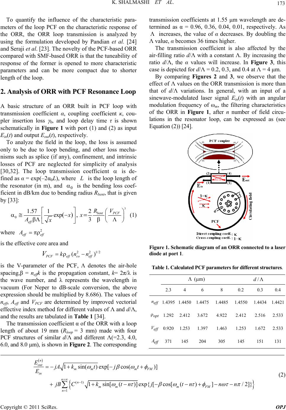 173 K. SHALMASHI ET AL. To quantify the influence of the characteristic para- meters of the loop PCF on the characteristic response of the ORR, the ORR loop transmission is analyzed by using the formulation developed by Pandian et al. [24] and Seraji et al. [23]. The novelty of the PCF-based ORR compared with SMF-based ORR is that the tuneability of response of the former is opened to more characteristic parameters and can be more compact due to shorter length of the loop. 2. Analysis of ORR with PCF Resonance Loop A basic structure of an ORR built in PCF loop with transmission coefficient α, coupling coefficient κ, cou- pler insertion loss 0, and loop delay time τ is shown schematically in Figure 1 with port (1) and (2) as input Ein(t) and output Eout(t), respectively. To analyze the field in the loop, the loss is assumed only to be due to loop bending, and other loss mecha- nisms such as splice (if any), confinement, and intrinsic losses of PCF are neglected for simplicity of analysis [30,32]. The loop transmission coefficient is de- fined as α = exp(–2α0L), where L is the loop length of the resonator (in m), and 0 is the bending loss coef- ficient in dB/km due to bending radius Rbent, that is given by [33]: 3 0 1.57 12 exp 3 (), bent PCF eff RV xx Ax (1) where 2 eff eff A is the effective core area and 22 1/2 () PCFeff coeff knnV is the V-parameter of the PCF, denotes the air-hole spacing,β = neffk is the propagation constant, k= 2π/λ is the wave number, and λ represents the wavelength in vacuum (For Neper to dB-scale conversion, the above expression should be multiplied by 8.686). The values of neff, Aeff and VPCF are determined by improved vectorial effective index method for different values of Λ and d/Λ, and the results are tabulated in Table 1 [34]. The transmission coefficient α of the ORR with a loop length of about 19 mm (Rloop = 3 mm) made with four PCF structures of similar d/Λ and different Λ(=2.3, 4.0, 6.0, and 8.0 m), is shown in Figure 2. The corresponding transmission coefficients at 1.55 m wavelength are de- termined as α = 0.96, 0.36, 0.04, 0.01, respectively. As increases, the value of α decreases. By doubling the Λ value, α becomes 36 times higher. The transmission coefficient is also affected by the air-filling ratio d/Λ with a constant Λ. By increasing the ratio d/Λ, the α values will increase. In Figure 3, this case is depicted for d/Λ = 0.2, 0.3, and 0.4 at Λ = 4 μm. By comparing Figures 2 and 3, we observe that the effect of Λ values on the ORR transmission is more than that of d/Λ variations. In general, with an input of a sinewave-modulated laser signal Ein(t) with an angular modulation frequency of ωm, the filtering characteristics of the ORR in Figure 1, after n number of field circu- lations in the resonator loop, can be expressed as (see Equation (2)) [24]. Figure 1. Schematic diagram of an ORR connected to a laser diode at port 1. Table 1. Calculated PCF parameters for different structures. (m) /d 2.34 6 8 0.2 0.3 0.4 eff n1.43951.44501.4475 1.4485 1.4550 1.44341.4421 opt 1.2922.4123.672 4.922 2.412 2.516 2.533 eff V0.9201.2531.397 1.463 1.253 1.672 2.533 eff A 371145 204 305 145 151 131 (1) 1 1sin() exp[cos()] 1sin[()]exp{[cos[()]/2]} n out mm mFM in nn mmm FM n EjA ktjt E jBCkt njt nnn (2) Copyright © 2011 SciRes. OPJ  K. SHALMASHI ET AL. 174 (a) (b) Figure 2. Transmission coefficient of the ORR in terms of wavelength for (a) d/Λ = 0.2, (b) d/Λ = 0.4, and different values of Λ. Figure 3. Transmission coefficient of the ORR in terms of wavelength forΛ = 4μm and different values of d/Λ. Where β = Imkf /fm is frequency modulation index, kf is the optical frequency deviation (Hz/mA), fm is modu- lation frequency, Im is the peak value of ac modulating current, km is the amplitude modulation index, ΦFM is angle between optical frequency deviation and amplitude modulating derive current of the given LD. (1 )A (1)(1 )B and (1 )C are constants and all other parameters have the same definitions as in Figure 1. With a particular characteristic parameters given in Table 2, a stop band filter based on ORR is designed with a characteristic response plotted in Figure 4 at reso- nance wavelength of 1.55 μm. The full-width at half ma- ximum of the filter for t = 50τis obtained as 5 nm. Figure 4. Characteristic response of stop band filter based on ORR. 3. Effects of Laser Diode Parameters To tune the filter based on the ORR, we can either change the parameters of the ORR such as d/Λ loop length, κ or/and parameters of input source such as fm and km [24]. For instance, by increasing fm from 95 GHz to 125 GHz, the resonance filter response shifts from 1.55 µm to 1.615 µm, respectively, as shown in Figure 5. The FWHM of the response slightly increases by increasing the modulation frequency of the input source. The amplitude modulation index km also affects the filter response. By increasing its value, the effectiveness of filtration increases at the central wavelength, as shown in Figure 6(a). Another parameter of laser diode source influencing on the filter response is the modulation current Im applied to the laser diode. Similar to effect of km, Im Copyright © 2011 SciRes. OPJ  175 K. SHALMASHI ET AL. influences the depth of characteristic response, which increases by increase of Im, as shown in Figure 6(b). In general, how the filter responds to the variation of Im is shown in Figure 7. At about Im = 40, 70, and 90 mA, the filter responses are at maximum values. Extreme low value occurs at about Im= 65 mA 4. Effects of PCF Parameters The transmission response of the filter strongly depends on the hole-spacing Λ of the PCF used in the loop of the resonator, as shown in Figure 8. For a given , when d/Λ goes higher, the filter response goes lower and for a given d/Λ, higher the value of Λ, lower will be the filter response. At a particular values of Λ and d/Λ, when the corre- sponding α value tends to the value of κ the filter res- ponse reaches its maximum value. 5. Effects of Characteristic Parameters of Coupler and Ring The coupling coefficient of the resonator κ has direct effects on the filter response. Figure 4 is reproduced here by changing the value of d/Λ from 0.4 to 0.2, keeping Λ = 0.4 μm. When d/Λ decreases, the value of κ decreases for better filter response, as illustrated in Figure 9. Therefore, for an optimum filter response, the values of km and κ should be as large as possible, whereas Λ should be as small as possible. For the best condition, Λ should (a) (b) Figure 6. Effect of (a) amplitude modulation index km and (b) modulating current Im on the filter response. Figure 5. Effect of modulating frequency fm on the filter response. Figure 7. Variation of filter response versus modulating current. Copyright © 2011 SciRes. OPJ 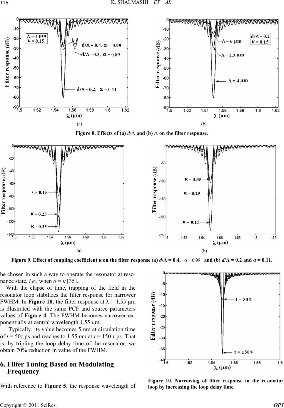 K. SHALMASHI ET AL. 176 (a) (b) Figure 8. Effects of (a) d/Λ and (b) Λ on the filter response. (a) (b) Figure 9. Effect of coupling coefficient κ on the filter response (a) d/Λ = 0.4, 0.99 and (b) d/Λ = 0.2 and α = 0.11. be chosen in such a way to operate the resonator at reso- nance state, i.e., when α = κ [35]. With the elapse of time, trapping of the field in the resonator loop stabilizes the filter response for narrower FWHM. In Figure 10, the filter response at λ = 1.55 μm is illustrated with the same PCF and source parameters values of Figure 4. The FWHM becomes narrower ex- ponentially at central wavelength 1.55 m. Typically, its value becomes 5 nm at circulation time of t = 50τ ps and reaches to 1.55 nm at t = 150 τ ps. That is, by tripling the loop delay time of the resonator, we obtain 70% reduction in value of the FWHM. 6. Filter Tuning Based on Modulating Frequency With reference to Figure 5, the response wavelength of Figure 10. Narrowing of filter response in the resonator loop by increasing the loop delay time. Copyright © 2011 SciRes. OPJ 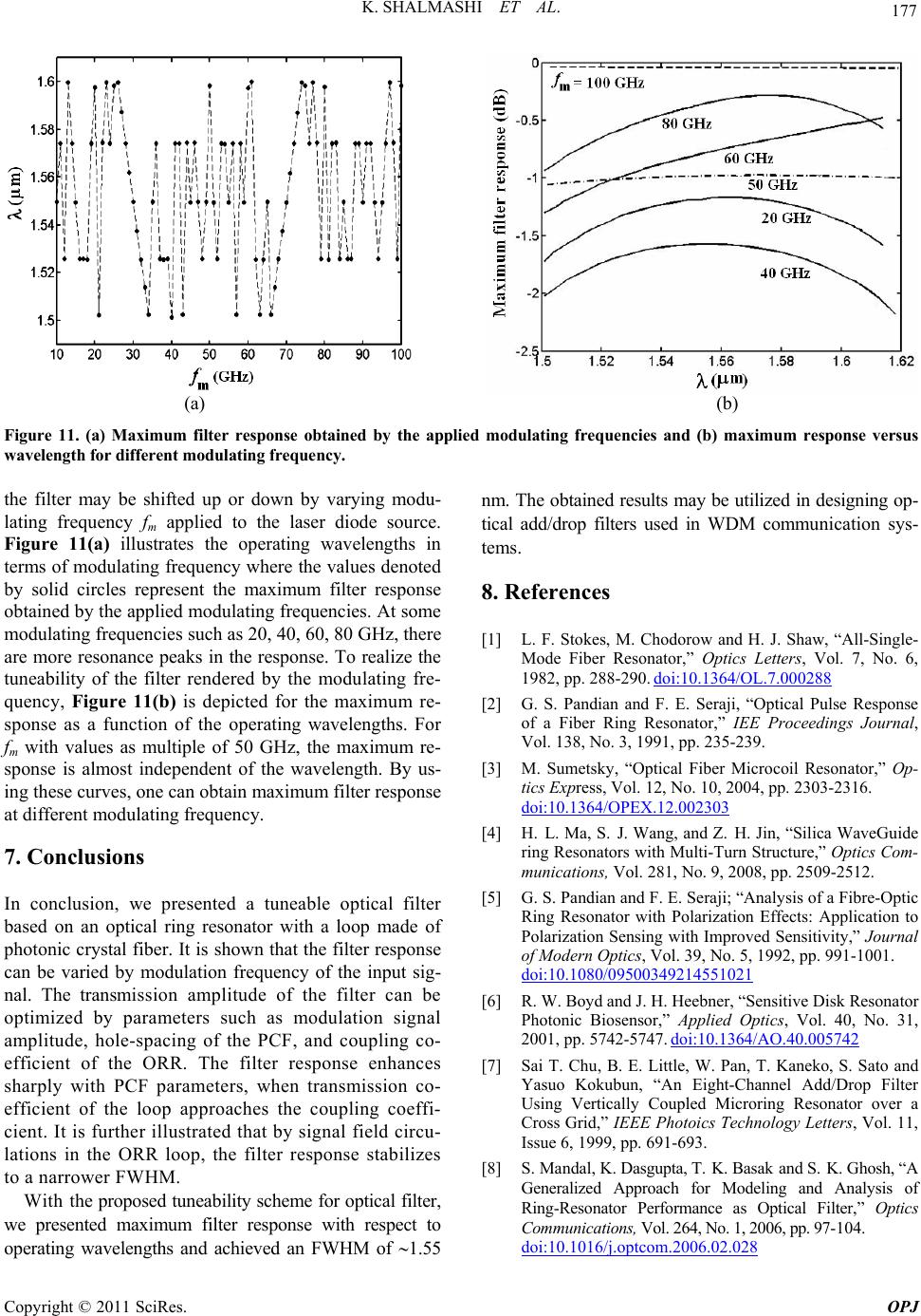 177 K. SHALMASHI ET AL. (a) (b) Figure 11. (a) Maximum filter response obtained by the applied modulating frequencies and (b) maximum response versus wavelength for different modulating frequency. the filter may be shifted up or down by varying modu- lating frequency fm applied to the laser diode source. Figure 11(a) illustrates the operating wavelengths in terms of modulating frequency where the values denoted by solid circles represent the maximum filter response obtained by the applied modulating frequencies. At some modulating frequencies such as 20, 40, 60, 80 GHz, there are more resonance peaks in the response. To realize the tuneability of the filter rendered by the modulating fre- quency, Figure 11(b) is depicted for the maximum re- sponse as a function of the operating wavelengths. For fm with values as multiple of 50 GHz, the maximum re- sponse is almost independent of the wavelength. By us- ing these curves, one can obtain maximum filter response at different modulating frequency. 7. Conclusions In conclusion, we presented a tuneable optical filter based on an optical ring resonator with a loop made of photonic crystal fiber. It is shown that the filter response can be varied by modulation frequency of the input sig- nal. The transmission amplitude of the filter can be optimized by parameters such as modulation signal amplitude, hole-spacing of the PCF, and coupling co- efficient of the ORR. The filter response enhances sharply with PCF parameters, when transmission co- efficient of the loop approaches the coupling coeffi- cient. It is further illustrated that by signal field circu- lations in the ORR loop, the filter response stabilizes to a narrower FWHM. With the proposed tuneability scheme for optical filter, we presented maximum filter response with respect to operating wavelengths and achieved an FWHM of 1.55 nm. The obtained results may be utilized in designing op- tical add/drop filters used in WDM communication sys- tems. 8. References [1] L. F. Stokes, M. Chodorow and H. J. Shaw, “All-Single- Mode Fiber Resonator,” Optics Letters, Vol. 7, No. 6, 1982, pp. 288-290. doi:10.1364/OL.7.000288 [2] G. S. Pandian and F. E. Seraji, “Optical Pulse Response of a Fiber Ring Resonator,” IEE Proceedings Journal, Vol. 138, No. 3, 1991, pp. 235-239. [3] M. Sumetsky, “Optical Fiber Microcoil Resonator,” Op- tics Express, Vol. 12, No. 10, 2004, pp. 2303-2316. doi:10.1364/OPEX.12.002303 [4] H. L. Ma, S. J. Wang, and Z. H. Jin, “Silica WaveGuide ring Resonators with Multi-Turn Structure,” Optics Com- munications, Vol. 281, No. 9, 2008, pp. 2509-2512. [5] G. S. Pandian and F. E. Seraji; “Analysis of a Fibre-Optic Ring Resonator with Polarization Effects: Application to Polarization Sensing with Improved Sensitivity,” Journal of Modern Optics, Vol. 39, No. 5, 1992, pp. 991-1001. doi:10.1080/09500349214551021 [6] R. W. Boyd and J. H. Heebner, “Sensitive Disk Resonator Photonic Biosensor,” Applied Optics, Vol. 40, No. 31, 2001, pp. 5742-5747. doi:10.1364/AO.40.005742 [7] Sai T. Chu, B. E. Little, W. Pan, T. Kaneko, S. Sato and Yasuo Kokubun, “An Eight-Channel Add/Drop Filter Using Vertically Coupled Microring Resonator over a Cross Grid,” IEEE Photoics Technology Letters, Vol. 11, Issue 6, 1999, pp. 691-693. [8] S. Mandal, K. Dasgupta, T. K. Basak and S. K. Ghosh, “A Generalized Approach for Modeling and Analysis of Ring-Resonator Performance as Optical Filter,” Optics Communi cations, Vol. 264, No. 1, 2006, pp. 97-104. doi:10.1016/j.optcom.2006.02.028 Copyright © 2011 SciRes. OPJ 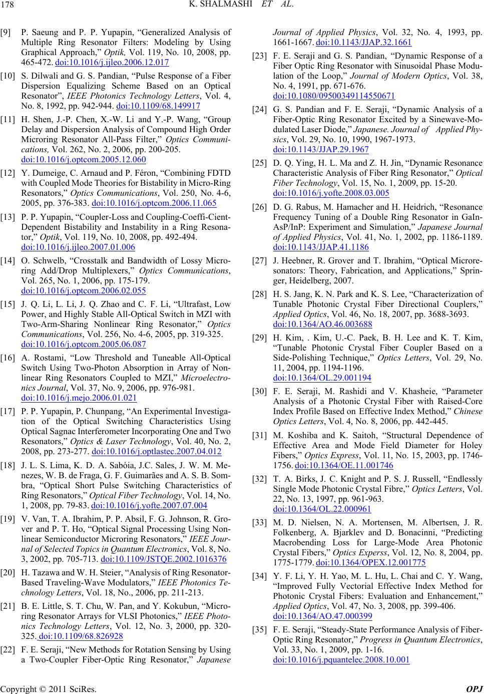 K. SHALMASHI ET AL. 178 [9] P. Saeung and P. P. Yupapin, “Generalized Analysis of Multiple Ring Resonator Filters: Modeling by Using Graphical Approach,” Optik, Vol. 119, No. 10, 2008, pp. 465-472. doi:10.1016/j.ijleo.2006.12.017 [10] S. Dilwali and G. S. Pandian, “Pulse Response of a Fiber Dispersion Equalizing Scheme Based on an Optical Resonator”, IEEE Photonics Technology Letters, Vol. 4, No. 8, 1992, pp. 942-944. doi:10.1109/68.149917 [11] H. Shen, J.-P. Chen, X.-W. Li and Y.-P. Wang, “Group Delay and Dispersion Analysis of Compound High Order Microring Resonator All-Pass Filter,” Optics Communi- cations, Vol. 262, No. 2, 2006, pp. 200-205. doi:10.1016/j.optcom.2005.12.060 [12] Y. Dumeige, C. Arnaud and P. Féron, “Combining FDTD with Coupled Mode Theories for Bistability in Micro-Ring Resonators,” Optics Communications, Vol. 250, No. 4-6, 2005, pp. 376-383. doi:10.1016/j.optcom.2006.11.065 [13] P. P. Yupapin, “Coupler-Loss and Coupling-Coeffi-Cient- Dependent Bistability and Instability in a Ring Resona- tor,” Optik, Vol. 119, No. 10, 2008, pp. 492-494. doi:10.1016/j.ijleo.2007.01.006 [14] O. Schwelb, “Crosstalk and Bandwidth of Lossy Micro- ring Add/Drop Multiplexers,” Optics Communications, Vol. 265, No. 1, 2006, pp. 175-179. doi:10.1016/j.optcom.2006.02.055 [15] J. Q. Li, L. Li, J. Q. Zhao and C. F. Li, “Ultrafast, Low Power, and Highly Stable All-Optical Switch in MZI with Two-Arm-Sharing Nonlinear Ring Resonator,” Optics Communications, Vol. 256, No. 4-6, 2005, pp. 319-325. doi:10.1016/j.optcom.2005.06.087 [16] A. Rostami, “Low Threshold and Tuneable All-Optical Switch Using Two-Photon Absorption in Array of Non- linear Ring Resonators Coupled to MZI,” Microelectro- nics Journal, Vol. 37, No. 9, 2006, pp. 976-981. doi:10.1016/j.mejo.2006.01.021 [17] P. P. Yupapin, P. Chunpang, “An Experimental Investiga- tion of the Optical Switching Characteristics Using Optical Sagnac Interferometer Incorporating One and Two Resonators,” Optics & Laser Technology, Vol. 40, No. 2, 2008, pp. 273-277. doi:10.1016/j.optlastec.2007.04.012 [18] J. L. S. Lima, K. D. A. Sabóia, J.C. Sales, J. W. M. Me- nezes, W. B. de Fraga, G. F. Guimarães and A. S. B. Som- bra, “Optical Short Pulse Switching Characteristics of Ring Resonators,” Optical Fiber Technology, Vol. 14, No. 1, 2008, pp. 79-83. doi:10.1016/j.yofte.2007.07.004 [19] V. Van, T. A. Ibrahim, P. P. Absil, F. G. Johnson, R. Gro- ver and P. T. Ho, “Optical Signal Processing Using Non- linear Semiconductor Microring Resonators,” IEEE Jour- nal of Selected Topics in Quantum Electronics, Vol. 8, No. 3, 2002, pp. 705-713. doi:10.1109/JSTQE.2002.1016376 [20] H. Tazawa and W. H. Steier, “Analysis of Ring Resonator- Based Traveling-Wave Modulators,” IEEE Photonics Te- chnology Letters, Vol. 18, No., 2006, pp. 211-213. [21] B. E. Little, S. T. Chu, W. Pan, and Y. Kokubun, “Micro- ring Resonator Arrays for VLSI Photonics,” IEEE Photo- nics Technology Letters, Vol. 12, No. 3, 2000, pp. 320- 325. doi:10.1109/68.826928 [22] F. E. Seraji, “New Methods for Rotation Sensing by Using a Two-Coupler Fiber-Optic Ring Resonator,” Japanese Journal of Applied Physics, Vol. 32, No. 4, 1993, pp. 1661-1667. doi:10.1143/JJAP.32.1661 [23] F. E. Seraji and G. S. Pandian, “Dynamic Response of a Fiber Optic Ring Resonator with Sinusoidal Phase Modu- lation of the Loop,” Journal of Modern Optics, Vol. 38, No. 4, 1991, pp. 671-676. doi:10.1080/09500349114550671 [24] G. S. Pandian and F. E. Seraji, “Dynamic Analysis of a Fiber-Optic Ring Resonator Excited by a Sinewave-Mo- dulated Laser Diode,” Japanese. Journal of Applied Phy- sics, Vol. 29, No. 10, 1990, 1967-1973. doi:10.1143/JJAP.29.1967 [25] D. Q. Ying, H. L. Ma and Z. H. Jin, “Dynamic Resonance Characteristic Analysis of Fiber Ring Resonator,” Optical Fiber Technology, Vol. 15, No. 1, 2009, pp. 15-20. doi:10.1016/j.yofte.2008.03.005 [26] D. G. Rabus, M. Hamacher and H. Heidrich, “Resonance Frequency Tuning of a Double Ring Resonator in GaIn- AsP/InP: Experiment and Simulation,” Japanese Journal of Applied Physics, Vol. 41, No. 1, 2002, pp. 1186-1189. doi:10.1143/JJAP.41.1186 [27] J. Heebner, R. Grover and T. Ibrahim, “Optical Microre- sonators: Theory, Fabrication, and Applications,” Sprin- ger, Heidelberg, 2007. [28] H. S. Jang, K. N. Park and K. S. Lee, “Characterization of Tunable Photonic Crystal Fiber Directional Couplers,” Applied Optics, Vol. 46, No. 18, 2007, pp. 3688-3693. doi:10.1364/AO.46.003688 [29] H. Kim, . Kim, U.-C. Paek, B. H. Lee and K. T. Kim, “Tunable Photonic Crystal Fiber Coupler Based on a Side-Polishing Technique,” Optics Letters, Vol. 29, No. 11, 2004, pp. 1194-1196. doi:10.1364/OL.29.001194 [30] F. E. Seraji, M. Rashidi and V. Khasheie, “Parameter Analysis of a Photonic Crystal Fiber with Raised-Core Index Profile Based on Effective Index Method,” Chinese Optics Letters, Vol. 4, No. 8, 2006, pp. 442-445. [31] M. Koshiba and K. Saitoh, “Structural Dependence of Effective Area and Mode Field Diameter for Holey Fibers,” Optics Express, Vol. 11, No. 15, 2003, pp. 1746- 1756. doi:10.1364/OE.11.001746 [32] T. A. Birks, J. C. Knight and P. S. J. Russell, “Endlessly Single Mode Photonic Crystal Fibre,” Optics Letters, Vol. 22, No. 13, 1997, pp. 961-963. doi:10.1364/OL.22.000961 [33] M. D. Nielsen, N. A. Mortensen, M. Albertsen, J. R. Folkenberg, A. Bjarklev and D. Bonacinni, “Predicting Macrobending Loss for Large-Mode Area Photonic Crystal Fibers,” Optics Experss, Vol. 12, No. 8, 2004, pp. 1775-1779. doi:10.1364/OPEX.12.001775 [34] Y. F. Li, Y. H. Yao, M. L. Hu, L. Chai and C. Y. Wang, “Improved Fully Vectorial Effective Index Method for Photonic Crystal Fibers: Evaluation and Enhancement,” Applied Optics, Vol. 47, No. 3, 2008, pp. 399-406. doi:10.1364/AO.47.000399 [35] F. E. Seraji, “Steady-State Performance Analysis of Fiber- Optic Ring Resonator,” Progress in Quantum Electronics, Vol. 33, No. 1, 2009, pp. 1-16. doi:10.1016/j.pquantelec.2008.10.001 Copyright © 2011 SciRes. OPJ |