

Paper Menu >>
Journal Menu >>
 Optics and Photonics Journal, 2011, 1, 179-188 doi:10.4236/opj.2011.14029 Published Online December 2011 (http://www.SciRP.org/journal/opj) Copyright © 2011 SciRes. OPJ Analysis of the Impact of P-Ratio on BER, Q-Factor and OSNR of Radio over Fiber (RoF) System Vishal Sharma1, Amarpal Singh2, Ajay K. Sharma3 1Shaheed Bhagat Singh College of Engineering and Technology, Ferozepur, India 2Beant College of Engineering and Technology, Gurdaspur, India 3Dr. B.R. Ambedkar NIT, Jalandhar, India E-mail: [email protected] Received September 15, 2011; revised October 15, 2011; accepted November 6, 2011 Abstract The impact of p-ratio i.e. ratio of carrier power to total received RF power at control office (CO) on Bit error rate (BER), Q- performance parameter and Optical signal noise ratio (OSNR) of RoF communication system is theoretically analyzed using angular full-linewidth at half maximum (FWHM) of Lorentzian shape for the RF oscillator in this paper. As reduction in Laser linewidth improves the performance of RoF system, the RF oscillator linewidth at FWHM also plays an important role in improving the performance of RoF system. Keywords: RoF System, OSNR Parameter, BER, Q-Parameter, Fiber Dispersion, Matlab 7.0 1. Introduction For realization of future high performance integrated networks, broadband distribution & access networks and to meet the increasing demand of multimedia services with a guaranteed quality of service, RoF technology comes out as the most promising technology. RoF tech- nology combines the capacity of optical networks with the flexibility and mobility of wireless networks. Reduc- tion in complexity at the antenna site, reduction in in- stallation cost of access networks, possibility of dy- namically allocation of radio carriers to different an- tenna sites, transparency and scalability are the few ad- vantages of RoF technology. These systems have several advantages including lower attenuation compared to the coaxial cable, higher bandwidth, immunity to the RF interference and durability [1-4]. Modulation technique is one of the most significant processes in RoF system where the RF electrical signal is applied to modulate the optical carrier. RoF modulation methods can be catego- rized into two main groups: direct modulation and exter- nal modulation. Direct modulation, a simple technique, directly modulates the amplitude of the laser beam but suffers from a laser-frequency chirp effect that degrades severely the performance of the system. However, this can be eliminated by using the external-modulation scheme [5] used to modulate the phase of the optical carrier. Furthermore, the conventional optical double sideband (ODSB) external modulation scheme degrades the received RF signal power due to fiber chromatic dis- persion drastically. For frequency range beyond 5 GHz external modulation is needed for higher speeds. No doubt such systems are capable of meeting the future requirements of High speed high data transfer services but some degradations effects the performance of such systems such as fiber dispersion and modulator’s non- nearity. For overcoming this power degradation, an opti- cal single sideband (OSSB) external modulation scheme is employed [5]. The effect of phase noises from a laser and an oscillator on OSSB-RoF system is analyzed and discussed [6]. Barry and Lee [7] and Salz [8] also ana- lyzed the performance of coherent optical systems with laser phase noise by utilizing a wiener process as coher- ent detection provides better sensitivity than that of di- rect detection. A number of techniques have been in- vented to analyze and improve the performance of RoF system by mitigating these problems. Minimization of fiber dispersion using OSSB technique, reduction of laser linewidth [9] and using external modulators are the few important techniques. In this paper, we have analyzed theoretically the impact of p-ratio over per- formance parameters of RoF communication system us- ing angular full-linewidth at half maximum (FWHM) of Lorentzian shape of the RF oscillator at different optical 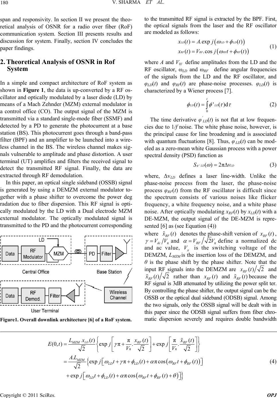 V. SHARMA ET AL. 180 span and responsivity. In section II we present the theo- retical analysis of OSNR for a radio over fiber (RoF) communication system. Section III presents results and discussion for system. Finally, section IV concludes the paper findings. 2. Theoretical Analysis of OSNR in Rof System In a simple and compact architecture of RoF system as shown in Figure 1, the data is up-converted by a RF os- cillator and optically modulated by a laser diode (LD) by means of a Mach Zehnder (MZM) external modulator in a control office (CO). The output signal of the MZM is transmitted via a standard single-mode fiber (SSMF) and detected by a PD to generate the photocurrent at a base station (BS). This photocurrent goes through a band-pass filter (BPF) and an amplifier to be launched into a wire- less channel in the BS. The wireless channel makes sig- nals vulnerable to amplitude and phase distortion. A user terminal (UT) amplifies and filters the received signal to detect the transmitted RF signal. Finally, the data are extracted through RF demodulation. In this paper, an optical single sideband (OSSB) signal is generated by using a DEMZM external modulator to- gether with a phase shifter to overcome the power deg radation due to fiber dispersion. This RF signal is opti- cally modulated by the LD with a Dual electrode MZM external modulator. The optically modulated signal is transmitted to the PD and the photocurrent corresponding Figure1. Overall downlink architecture [6] of a RoF system. to the transmitted RF signal is extracted by the BPF. First, the optical signals from the laser and the RF oscillator are modeled as follows: () .exp() () .cos() LDLD LD RFRFRF RF x tA jt x tVj tt (1) where A and VRF define amplitudes from the LD and the RF oscillator, ωLD and ωRF define angular frequencies of the signals from the LD and the RF oscillator, and φLD(t) and φRF(t) are phase-noise processes. φLD(t) is characterized by a Wiener process [7]. 0 ()'( )dLD LD t t (2) The time derivative φ’ LD(t) is not flat at low frequen- cies due to 1/f noise. The white phase noise, however, is the principal cause for line broadening and is associated with quantum fluctuations [8]. Thus, φ' LD(t) can be mod- eled as a zero-mean white Gaussian process with a power spectral density (PSD) function as '() 2π L DS LDv (3) where, ΔvLD defines a laser line-width. Unlike the phase-noise process from the laser, the phase-noise process φRF(t) from the RF oscillator is difficult since the spectrum consists of various noises like flicker frequency, a white frequency noise, and a white phase noise. After optically modulating xRF(t) by xLD(t) with a DE-MZM, the output signal of the DE-MZM is repre- sented [6] as (see Equation (4)) where () RF x t denotes the phase-shift version of() RF x t, πdc VV and π 2 RF V Vdefine a normalized dc and ac value, V is the switching voltage of the DEMZM, LMZM is the insertion loss of the DEMZM, and θ is the phase shift by the phase shifter. Note that the input RF signals into the DEMZM are () 2 RF xt and ()2 RF xt rather than () RF x t and () RF x t because the RF signal is 3dB attenuated by utilizing the power split ter. By controlling the phase shifter, the output signal can be the OSSB or the optical dual sideband (ODSB) signal. Among the two signals, only the OSSB signal will be dealt with in this paper since the ODSB signal suffers from fiber chro- matic dispersion severely and requires double bandwidth . ππ ()() () ππ (0,)expπ.exp. 22 .exp π() πcos( ) 2 exp( )πcos( ) LD MZMRF RF MZM LDLDRF RF LD LDRFRF Lxtxt xt Et jj VV AL jttt t jt tt t 2 (4) Copyright © 2011 SciRes. OPJ 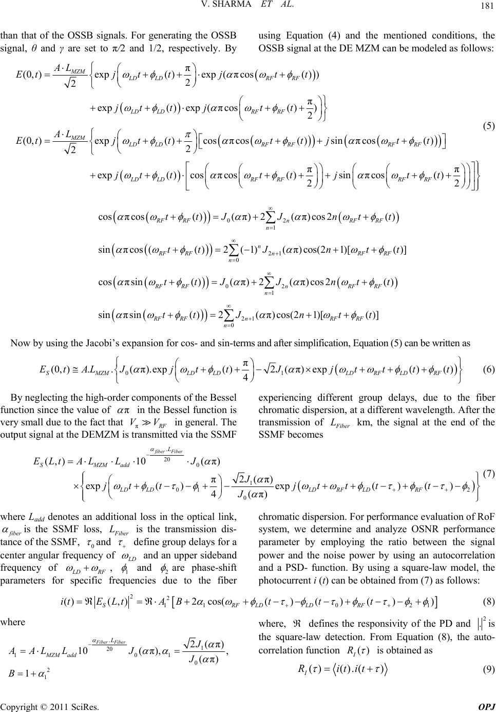 181 V. SHARMA ET AL. than that of the OSSB signals. For generating the OSSB signal, θ and γ are set to π/2 and 1/2, respectively. By using Equation (4) and the mentioned conditions, the OSSB signal at the DE MZM can be modeled as follows: π (0,)exp( )exp(πcos( )) 2 2 π exp( )exp(πcos( )) 2 (0,)exp( )cosπcos( )sinπcos ( 2 2 MZM LD LDRF RF LD LDRFRF MZM LDLDRF RFRF RF AL Etj ttjtt jt tjt t AL Etj ttttjtt ) ππ exp( )cosπcos( )sinπcos( ) 22 LD LDRFRFRFRF jt tt tjtt (5) 02 1 21 0 02 1 2 cos πcos( )(π)2(π)cos2( ) sin πcos(( )2(1)(π)cos(21)[( )] cos πsin( )(π)2 (π)cos2( ) sin πsin( )2 RF RFnRF RF n n RF RFnRF RF n RF RFnRF RF n RF RFn ttJJ ntt ttJn tt ttJJ ntt tt J 1 0 (π)cos(21)[( )] RF RF n ntt Now by using the Jacobi’s expansion for cos- and sin-terms and after simplification, Equation (5) can be written as 01 π (0, )..(π).exp( )2(π) exp()() 4 SMZMLD LDLDRFLDRF EtALJjt tJjtt tt (6) By neglecting the high-order components of the Bessel function since the value of π in the Bessel function is very small due to the fact that π R F in general. The output signal at the DEMZM is transmitted via the SSMF experiencing different group delays, due to the fiber chromatic dispersion, at a different wavelength. After the transmission of VV F iber L km, the signal at the end of the SSMF becomes . 20 0 1 01 2 0 (,)10 (π) 2(π) π exp()exp()() 4(π) fiber Fiber L SMZM add LD LDLDRFLDRF ELt ALLJ J jt tjtt tt J (7) where Ladd denotes an additional loss in the optical link, f iber is the SSMF loss, F iber L is the transmission dis- tance of the SSMF, 0 and define group delays for a center angular frequency of L D and an upper sideband frequency of L DRF , 1 and 2 are phase-shift parameters for specific frequencies due to the fiber chromatic dispersion. For performance evaluation of RoF system, we determine and analyze OSNR performance parameter by employing the ratio between the signal power and the noise power by using an autocorrelation and a PSD- function. By using a square-law model, the photocurrent i (t) can be obtained from (7) as follows: 22 110 2 ()(,)2cos(()()()) SRFLDLDRF itE LtABttt1 (8) where . 1 20 101 0 2 1 2(π) 10( π), , (π) 1 Fiber Fiber L MZM add J AAL LJJ B where, defines the responsivity of the PD and 2 .is the square-law detection. From Equation (8), the auto- correlation function () I R is obtained as () ().() I Ritit (9) Copyright © 2011 SciRes. OPJ 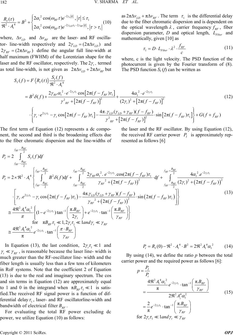 V. SHARMA ET AL. 182 1 2 2 1 2 24 22 2 11 1 2cos( ), () 2cos( ), e LD RF RF I RF e RB Ae 1 (10) where, L D v and R F v are the laser- and RF oscilla- tor- line-width respectively and 2(2π) L D vLD and 2(2π) R F vRF define the angular full line-width at half maximum (FWHM) of the Lorentzian shape for the laser and the RF oscillator, respectively. The2t , termed as total line-width, is not given as 2π2π L DR vv as 2ππ L D vv RF . The term 1 is the differential delay due to the fiber chromatic dispersion and is dependent on the optical wavelength , carrier frequency R F f , fiber dispersion parameter, D and optical length, F ibe Lr and mathematically, given [10] as 2 1 R F Fiber f DL c (11) where, c is the light velocity. The PSD function of the photocurrent is given by the Fourier transform of (8). The PSD function SI (f) can be written as F but 11 1 24 1 2 22 2 11 21 22 22 2 12 2 () () () 2cos2π() 4 () 2π() (2)2π() 4π.()( ) cos2π() sin2π( 2π() et t I II RF RF RF RFtRF LD LDRFRF tt RF RF RF Sf Sf FRA effe Bf ff ff ff eff ff ff 1 )() R FR Gf f F (12) The first term of Equation (12) represents a dc compo- nent, the second and third is the broadening effects due to the fiber chromatic dispersion and the line-widths of the laser and the RF oscillator. By using Equation (12), the received RF carrier power I P is approximately rep- resented as follows [6] 1 1 1 2 2 2 2 2 2 22 2 24 2111 122 22 22 2 2 2()d 2..cos(2π() 4. 2()d d 2π() (2)2π() .c RF RF RF RF RF RFRF RF RFRF t t RF RFRF RF RFRF t B f II B f BB B ff f RF RF I BB B RF RFtRF ff f tt PSff effe PABff f ff ff e 11 1 1 2 2 242 22 11 11 1 4π.()( ) os 2π() sin2π() 2π() 4π.π. (1)tantan 2 forπ1, tt LD LDRFRF RF RF RF RF RF RF tRF RF ff ff ff ff ABB ee B 1 1 242 21 11 21 4tan π t ttRF RF RF and AB e (13) In Equation (13), the last condition, 1 2 t1 and tRF , is reasonable because the laser line- width is much greater than the RF-oscillator line- width and the fiber length is usually less than a few tens of kilometers in RoF systems. Note that the coefficient 2 of Equation (13) is due to the real and imaginary spectrum. The cos and sin terms in Equation (12) are approximately equal to 1 and 0 in the integrand when 1RF πB1 is satis- fied.The received RF signal power is a function of dif- ferential delay1 , laser- and RF oscillatorline-width and bandwidth of electrical filter R F For evaluating the total RF power excluding dc power, we utilize Equation (10) as follows: B. 24224 1 (0) 2 tI PRABA2 11 (14) By using (14), we define the ratio p between the total carrier power and the required power as follows [6]: 1 1 1 242 21 11 242 1 21 1 4π. tan π 2 π. 2tan π for 21 t t I t RF RF RF RF ttRF P pP AB e A B e and (15) Copyright © 2011 SciRes. OPJ 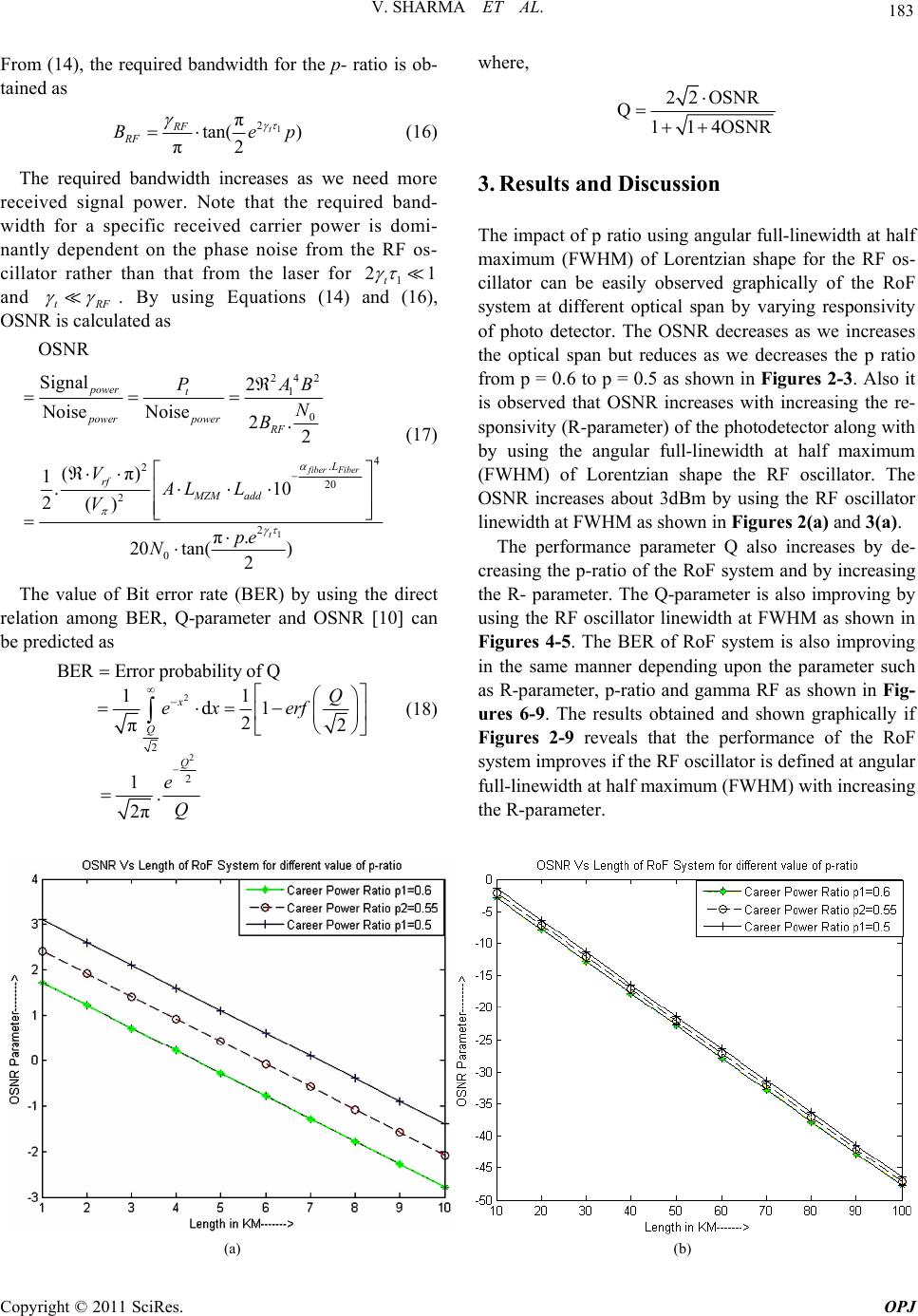 183 V. SHARMA ET AL. From (14), the required bandwidth for the p- ratio is ob- tained as 1 2 π tan( ) π2 t RF RF B ep 1 (16) The required bandwidth increases as we need more received signal power. Note that the required band- width for a specific received carrier power is domi- nantly dependent on the phase noise from the RF os- cillator rather than that from the laser for 1 2 t and tRF . By using Equations (14) and (16), OSNR is calculated as 1 242 1 0 4 . 2 20 2 2 0 OSNR Signal 2 Noise Noise2. 2 (π) 1.10 2() π. 20 tan() 2 fiberFiber t power t powerpower RF L rf MZM add PAB N B VAL L V pe N (17) The value of Bit error rate (BER) by using the direct relation among BER, Q-parameter and OSNR [10] can be predicted as 2 2 2 2 BERError probability of Q 11 d1 2 π2 1 . 2π x Q Q Q ex erf e Q (18) where, 22OSNR Q114OSNR 3. Results and Discussion The impact of p ratio using angular full-linewidth at half maximum (FWHM) of Lorentzian shape for the RF os- cillator can be easily observed graphically of the RoF system at different optical span by varying responsivity of photo detector. The OSNR decreases as we increases the optical span but reduces as we decreases the p ratio from p = 0.6 to p = 0.5 as shown in Figures 2-3. Also it is observed that OSNR increases with increasing the re- sponsivity (R-parameter) of the photodetector along with by using the angular full-linewidth at half maximum (FWHM) of Lorentzian shape the RF oscillator. The OSNR increases about 3dBm by using the RF oscillator linewidth at FWHM as shown in Figures 2(a) and 3(a). The performance parameter Q also increases by de- creasing the p-ratio of the RoF system and by increasing the R- parameter. The Q-parameter is also improving by using the RF oscillator linewidth at FWHM as shown in Figures 4-5. The BER of RoF system is also improving in the same manner depending upon the parameter such as R-parameter, p-ratio and gamma RF as shown in Fig- ures 6-9. The results obtained and shown graphically if Figures 2-9 reveals that the performance of the RoF system improves if the RF oscillator is defined at angular full-linewidth at half maximum (FWHM) with increasing the R-parameter. (a) (b) Copyright © 2011 SciRes. OPJ 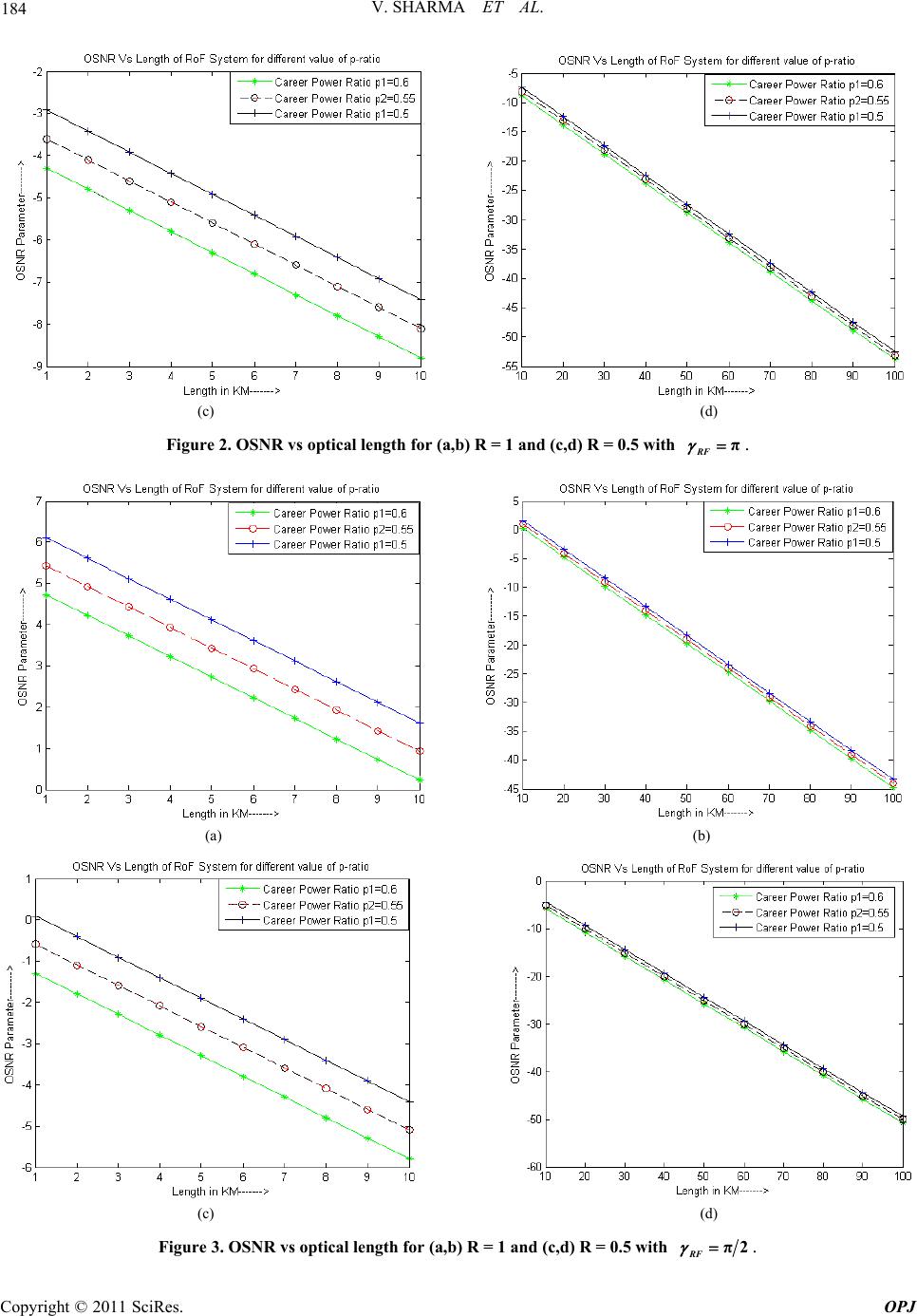 V. SHARMA ET AL. 184 (c) (d) Figure 2. OSNR vs optical length for (a,b) R = 1 and (c,d) R = 0.5 with . π RF (a) (b) (c) (d) Figure 3. OSNR vs optical length for (a,b) R = 1 and (c,d) R = 0.5 with π2 RF . Copyright © 2011 SciRes. OPJ 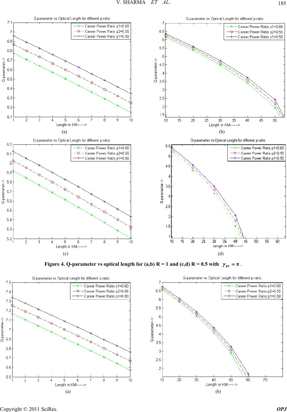 185 V. SHARMA ET AL. (a) (b) (c) (d) Figure 4. Q-parameter vs optical length for (a,b) R = 1 and (c,d) R = 0.5 with . π RF (a) (b) Copyright © 2011 SciRes. OPJ 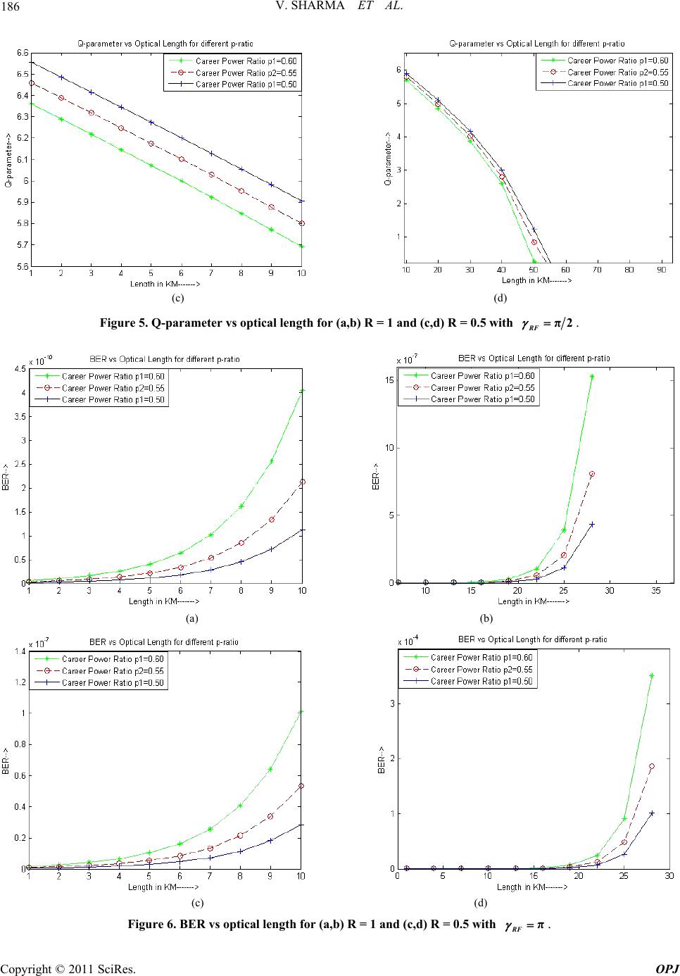 V. SHARMA ET AL. 186 (c) (d) Figure 5. Q-parameter vs optical length for (a,b) R = 1 and (c,d) R = 0.5 with π2 RF . (a) (b) (c) (d) Figure 6. BER vs optical length for (a,b) R = 1 and (c,d) R = 0.5 with . π RF Copyright © 2011 SciRes. OPJ  187 V. SHARMA ET AL. (a) (b) (c) (d) Figure 7. BER vs optical length for (a,b) R = 1 and (c,d) R = 0.5 with π2 RF . (a) (b) Figure 8. BER vs OSNR for (a) R = 1 and (b) R = 0.5 withπ RF . Copyright © 2011 SciRes. OPJ  V. SHARMA ET AL. Copyright © 2011 SciRes. OPJ 188 (a) (b) Figure 9. BER vs OSNR for (a) R = 1 and (b) R = 0.5 with π2 RF . 4. Conclusions [4] J. Hecht, “Understanding Fiber Optics,” 4th Edition, Pren- tice Hall, Upper Saddle River, 2002. In this paper, we have analyzed the impact of p-ratio on OSNR, Q-parameter and BER of RoF communication system at FWHM of RF oscillator linewidth in conjunc- tion with variable value of fiber length (LFiber) up to 100 Km. An improvement of 3 dBm in OSNR have been observed for p-ratio = 0.5 and π2 RF along with R-parameter of 1. A considerable improvement in Q- parameter and BER has also been observed for lesser value of p-ratio. [5] G. H. Smith and D. Novak, “Overcoming Chromatic- Dispersion Effects in Fiber-Wireless Systems Incorpo- rating External Modulators,” IEEE Transactions on Mi- crowave Theory Technology, Vol. 45, No. 8, 1997, pp. 1410-1415. doi:10.1109/22.618444 [6] T.-S. Cho, C. Yu and K. Kim, “Analysis of CNR Penalty of Radio over Fiber Systems Including the Effects of Phase Noise from Laser and RF Oscillator,” Journal of Lightwave Technology, Vol. 23, No. 12, 2005, pp. 4093- 4100. [7] J. R. Barry and E. A. Lee, “Performance of Coherent Optical Receivers,” Proceeding of Institute of Electrical Engineering, Vol. 78, No. 8, 1990, pp. 1369-1394. 5. References [1] N. Uesugi, T. Horiguchi, M. Nakazawa and Y. Murakami, “Optical Fiber Cable Measurements in the Field,” IEEE Journal on Selected Areas in Communications, Vol. 4, No. 5, 1986, pp.732-736. doi:10.1109/JSAC.1986.1146373 [8] J. Salz, “Modulation and Detection for Coherent Light- wave Communications,” IEEE Communication Magaga- zine, Vol. 24, No. 6, 1986, pp. 38-49. doi:10.1109/MCOM.1986.1093099 [9] V. Sharma, A. Singh and A. K. Sharma, “Analysis the Impact of Laser- and RF Oscillator-Line width over Car- rier-to- Noise Ratio in Optical Single Sideband (OSSB) RoF Transmission Systems”, Optics and Lasers in Engi- neering, Vol. 47, No. 11, 2009, pp. 1145-1149. doi:10.1016/j.optlaseng.2009.06.012 [2] M. Sauer, A. Kobyakov, J. E. Hurley and J. George, “Ex- perimental Study of Radio Frequency Transmission over Standard and High-Bandwidth Multimode Optical Fi- bers,” International Topical Meeting on Microwave Pho- tonics, Seoul, 12-14 October 2005, pp. 99-102. doi:10.1109/MWP.2005.203549 [10] U. Gliese, S. Nørskov and T. N. Nielsen, “Chromatic Dis- persion in Fiber-Optic Microwave and Millimeter-Wave Links,” IEEE Transaction of Microwave Theory Tech- nology, Vol. 44, No. 10, 1996, pp. 1716-1724. doi:10.1109/22.538964 [3] R. J. Green, “Secure Communications: The Infrared Al- ternative,” In ICTON Mediterranean Winter Conference, 6-8 December 2007, pp. 1- 4. doi:10.1109/ICTONMW.2007.4446906 |