

Paper Menu >>
Journal Menu >>
 Modern Mechanical Engineering, 2011, 1, 38-46 doi:10.4236/mme.2011.12006 Published Online November 2011 (http://www.SciRP.org/journal/mme) Copyright © 2011 SciRes. MME Virtual Prototype Modeling and Simulation of Pipe Wa gon Articulating System Ying Li1, Samuel Frimpong1, Wenyuan Liu2 1University of Missouri-Rolla, Rolla, USA 2Washington Uni versi t y in St . Loui s, St. Louis, USA E-mail: [email protected] Received September 9, 2011; revised October 18, 2011; acc epted Octo b er 25, 201 1 Abstract Virtual prototype of pipe wagon articulating (PWA) system has been developed and simulated based on the kinematics and dynamics of machinery and Automatic Dynamic Analysis of Mechanical Systems (A DAMS) software. It has been integrated with real-time three dimensional (3-D) system simulations for detailed and responsive interaction with dynamic virtual environments. By using this virtual model, the conceptual design examination and performance analysis of the PWA system have been realized dynamically in virtual labora- tory. System dynamic force, displacement and tension of pipe have been measured through verifying this 3- D virtual prototype. By comparing the static tension and dynamic tension of pipe, the difference between the two kind tensions has been found. The simulated dynamic tension is much greater than the static tension ob- tained from the static theory. The results attained in this work suggest that the conceptual designed PWA system can meet the requirements of the operation. Keywords: Pipe Wagon Articulating, Dynamic Modeling, Virtual Prototype, Dynamic Simulation 1. Introduction For efficient and economic extraction and haulage of oil sands from production faces, the “at face slurrying (AFS)” technology is currently being investig ated at the research and technology development lev els. The AFS techno logy will be used to create and transport oil san ds slurry from production faces through flexible pipeline system to link th e existing hydro-transpor t system. The three options have been proposed to transport oil sands slurry from the face to a fixed pipeline system based on preliminary economic modeling, simulation and analysis of various conceptual models. The PWA system is one of the three AFS options. A lot of efforts have been invested to conceptualization of the PWA mechanical system and detail numerical mod- eling for investigation of oil sands multiple-phase prob- lem in pipeline [1-4]. A conceptual design of the PWA system has been proposed in our lab. In this proposal, the PWA system is composed of linkages of pipe wagons connected with flexible pipes. This flexible arrangement accommodates the horizontal and vertical displacements of the mobile system as it follows the hydraulic shovels in the excavation process. In all research, a lot of attention has been given to study the single-phase and multiphase flow of oil sands slurry in PWA flexible pipe. The me- chanics of oil sands slurry flow in PWA flexible pipeline system has been formulated and simulated over an ex- tended period [1]. A numerical simulator has been deve- loped to provide nu merical solutions of the flow in flexi- ble pipe as a 3-D multiphase problem [2]. However, im- plementation of the PWA system in real-time and inside a v irtual environment, has not been carried out. And, there has not been investigation on system motion and engi- neering performance analysis of the PWA system so far. The continuing research will examine the handling per- formance of the system to represent the motions and for- ces of various components by modeling and simulateing real-word PWA system in a virtual laboratory. The literature that been reviewed in reference [5] in- dicates a consistent viewpoint of the virtual prototype mo- deling using to simulate the ground articulating pipeline (GAP) system. Therefore, this methodology still will be used in the simulation of the PWA system. Mechanical system simulation (MSS) in ADAMS software can be used for ongoing virtual modeling and simulation of the PWA system. MSS can be employed to simulate the mo- tion and force of the PWA systems based on machinery 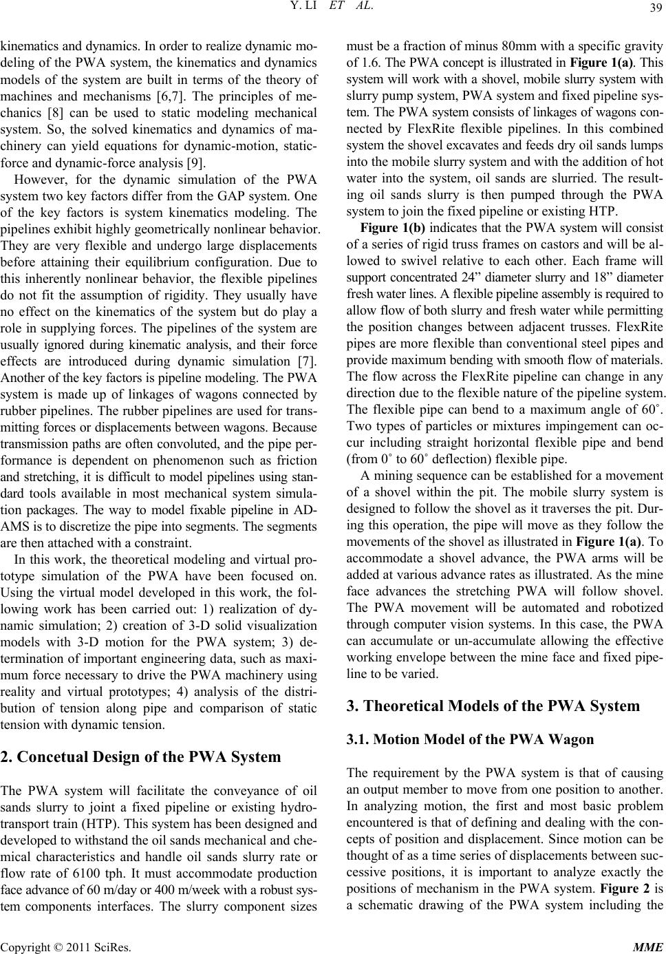 Y. LI ET AL. 39 kinematics and dynamics. In o rder to realize dynamic mo- deling of the PWA system, the kinematics and dynamics models of the system are built in terms of the theory of machines and mechanisms [6,7]. The principles of me- chanics [8] can be used to static modeling mechanical system. So, the solved kinematics and dynamics of ma- chinery can yield equations for dynamic-motion, static- force and dynamic-force analysis [9]. However, for the dynamic simulation of the PWA system two key factors differ from the GAP system. One of the key factors is system kinematics modeling. The pipelines exhibit highly geometrically nonlinear behavior. They are very flexible and undergo large displacements before attaining their equilibrium configuration. Due to this inherently nonlinear behavior, the flexible pipelines do not fit the assumption of rigidity. They usually have no effect on the kinematics of the system but do play a role in supplying forces. The pipelines of the system are usually ignored during kinematic analysis, and their force effects are introduced during dynamic simulation [7]. Another of the key factors is pipeline modeling. The PWA system is made up of linkages of wagons connected by rubber pipelines. The rubber pipelines are used for trans- mitting forces or displacements be tween wagons. Because transmission paths are often convoluted, and the pipe per- formance is dependent on phenomenon such as friction and stretching, it is difficult to model pipelines using stan- dard tools available in most mechanical system simula- tion packages. The way to model fixable pipeline in AD- AMS is to discretize th e pipe i n to seg ments. Th e seg ments are then attached with a constraint. In this work, the theoretical modeling and virtual pro- totype simulation of the PWA have been focused on. Using the virtual model developed in this work, the fol- lowing work has been carried out: 1) realization of dy- namic simulation; 2) creation of 3-D solid visualization models with 3-D motion for the PWA system; 3) de- termination of important engineering data, such as maxi- mum force necessary to drive the PWA machinery using reality and virtual prototypes; 4) analysis of the distri- bution of tension along pipe and comparison of static tension with dynamic tension. 2. Concetual Design of the PWA System The PWA system will facilitate the conveyance of oil sands slurry to joint a fixed pipeline or existing hydro- transport train (HTP). This system has been designed and developed to withstand the oil sands mechanical and che- mical characteristics and handle oil sands slurry rate or flow rate of 6100 tph. It must accommodate production face advance of 60 m/day or 400 m/week w ith a robu st sys- tem components interfaces. The slurry component sizes must be a fraction of minus 80mm with a specific gravity of 1.6. The PWA concept is illu strated in Figure 1(a). This system will work with a shovel, mobile slurry system with slurry pump system, PWA system and fixed pipeline sys- tem. The PWA system consists of linkages of wagons con- nected by FlexRite flexible pipelines. In this combined system the shovel excavates and feeds dry oil sands lumps into the mobile slurry system and with the addition of hot water into the system, oil sands are slurried. The result- ing oil sands slurry is then pumped through the PWA system to join the fixed pipeline or existing HTP. Figure 1(b) indicates that the PWA system will consis t of a series of rigid truss frames on castors and will be al- lowed to swivel relative to each other. Each frame will support concentrated 24” diameter slurry and 18” diamete r fresh water lines. A flexible pipeline assembly is required to allow flow of both slurry and fresh water while permitting the position changes between adjacent trusses. FlexRite pipes are more flexible than conventional steel pipes and provide maximum bending with smooth flow of materials. The flow across the FlexRite pipeline can change in any direction due to the flexible nature of the pipeline system. The flexible pipe can bend to a maximum angle of 60˚. Two types of particles or mixtures impingement can oc- cur including straight horizontal flexible pipe and bend (from 0˚ to 60˚ deflection) flexible pipe. A mining sequence can be established for a movement of a shovel within the pit. The mobile slurry system is designed to follow the shov el as it traverses the pit. Dur- ing this operation, the pipe will move as they follow the movements of the shovel as illustrated in Figure 1(a). To accommodate a shovel advance, the PWA arms will be added at various advance rates as illustrated . As the mine face advances the stretching PWA will follow shovel. The PWA movement will be automated and robotized through computer vision systems. In this case, the PWA can accumulate or un-accumulate allowing the effective working envelope between the mine face and fixed pipe- line to be varied. 3. Theoretical Models of the PWA System 3.1. Motion Model of the PWA Wagon The requirement by the PWA system is that of causing an output member to move from one position to another. In analyzing motion, the first and most basic problem encountered is that of defining and dealing with the con- cepts of position and displacement. Since motion can be thought of as a time series of displacements between suc- cessive positions, it is important to analyze exactly the positions of mechanism in the PWA system. Figure 2 is a schematic drawing of the PWA system including the Copyright © 2011 SciRes. MME 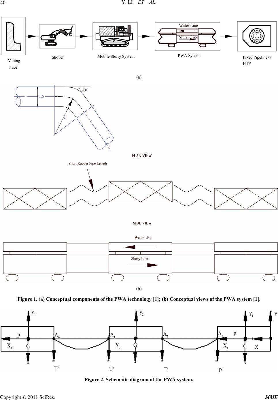 Y. LI ET AL. Copyright © 2011 SciRes. MME 40 (a) (b) Figure 1. (a) Conceptual components of the PWA technology [1]; (b) Conceptual views of the PWA system [1]. Figure 2. Schematic diagram of the PWA system. 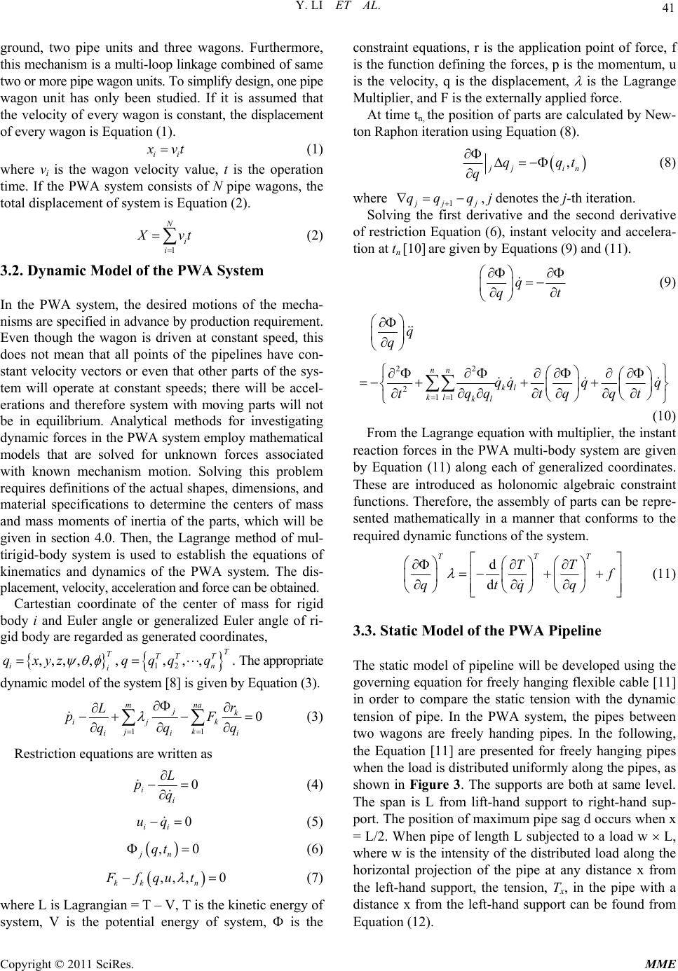 Y. LI ET AL. 41 ground, two pipe units and three wagons. Furthermore, th is mechanism is a multi-loop linkage combined of same two or more pipe wagon units. To simplify design, one pipe wagon unit has only been studied. If it is assumed that the velocity of every wagon is constant, the displacement of every wagon is Equation (1). ii x vt (1) where vi is the wagon velocity value, t is the operation time. If the PWA system consists of N pipe wagons, the total displacement of system is Equation (2). 1 N i i X vt (2) 3.2. Dynamic Model of the PWA System In the PWA system, the desired motions of the mecha- nisms are specified in advance by production requirement. Even though the wagon is driven at constant speed, this does not mean that all points of the pipelines have con- stant velocity vectors or even that other parts of the sys- tem will operate at constant speeds; there will be accel- erations and therefore system with moving parts will not be in equilibrium. Analytical methods for investigating dyna mic forces in the PWA system employ mathematical models that are solved for unknown forces associated with known mechanism motion. Solving this problem requires definitions of the actual shapes, dimensions, and material specifications to determine the centers of mass and mass moments of inertia of the parts, which will be given in section 4.0. Then, the Lagrange method of mul- tirigid-body system is used to establish the equations of kinematics and dynamics of the PWA system. The dis- placement, velocity, acceleration and force can be obtained. Cartestian coordinate of the center of mass for rigid body i and Euler angle or generalized Euler angle of ri- gid body a re regarde d as generate d coordinates, ,,,,, T ii qxyz ,. The appropriate dynamic model of the system [8] is given by Equation (3). 12 ,,, T TT T n qqq q 11 0 mna jk ijk jk ii r L pF qqq i (3) Restriction equations are written as 0 ii L pq (4) 0 ii uq (5) , jn qt0 (6) ,,, 0 kk n Ffqut (7) where L is Lagrangian = T – V, T is the kinetic energy of system, V is the potential energy of system, is the constraint equations, r is the application point of force, f is the function defining the forces, p is the momentum, u is the velocity, q is the displacement, is the Lagrange Multiplier, and F is the externally applied force. At time tn, the position of parts are calculated by New- ton Raphon iteration using Equation (8). , j ji qq qn t (8) where 1 j jj qq q , j denotes the j-th iteration. Solving the first derivative and the second derivative of restriction Equation (6), instant velocity and accelera- tion at tn [10] are given by Equations (9) and (11). q qt (9) 22 211 nn kl kl kl q q qqq q qqtqqt t (10) From the Lagrange equation with multiplier, the instant reaction forces in the PWA multi-body system are given by Equation (11) along each of generalized coordinates. These are introduced as holonomic algebraic constraint functions. Therefore, the assembly of parts can be repre- sented mathematically in a manner that conforms to the required dynamic functions of the system. d d TT TT T f qtqq (11) 3.3. Static Model of the PWA Pipeline The static model of pipeline will be developed using the governing equation for freely hanging flexible cable [11] in order to compare the static tension with the dynamic tension of pipe. In the PWA system, the pipes between two wagons are freely handing pipes. In the following, the Equation [11] are presented for freely hanging pipes when the load is distributed uniformly along the pipes, as shown in Figure 3. The supports are both at same level. The span is L from lift-hand support to right-hand sup- port. The position of maximum pipe sag d occurs when x = L/2. When pipe of length L subjected to a load w L, where w is the intensity of the distributed load along the horizontal projection of the pipe at any distance x from the left-hand support, the tension, Tx, in the pipe with a distance x from the left-hand support can be found from Equation (12) . Copyright © 2011 SciRes. MME 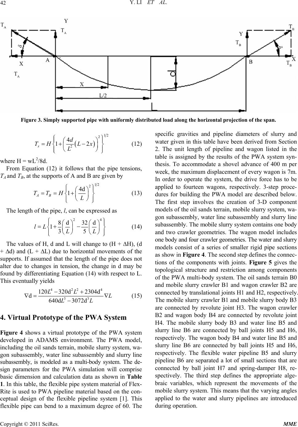 Y. LI ET AL. 42 Figure 3. Simply supported pipe with uniformly distributed load along the hori zontal projec tion of the span. 12 2 2 4 12 xd TH Lx L (12) where H = wL2/8d. From Equation (12) it follows that the pipe tensions, TA and TB, at the supports of A and B are given by 12 2 4d 1 AB TTH L (13) The length of the pipe, l, can be expressed as 24 8d 32d 135 lL LL (14) The values of H, d and L will change to (H + H), (d + d) and (L + L) due to horizontal movements of the supports. If assumed that the length of the pipe does not alter due to changes in tension, the change in d may be found by differentiating Equation (14) with respect to L. This eventually yields 422 4 33 120 320d2304d d640d 3072d LL L LL (15) 4. Virtual Prototype of the PWA System Figure 4 shows a virtual prototype of the PWA system developed in ADAMS environment. The PWA model, including the oil sands terrain, mobile slurry system, wa- gon subassembly, water line subassembly and slurry line subassembly, is modeled as a multi-body system. The de- sign parameters for the PWA simulation will comprise basic dimension and calculation data as shown in Table 1. In this table, the flexible pipe system material of Flex- Rite is used to PWA pipeline material based on the con- ceptual design of the flexible pipeline system [1]. This flexible pipe can bend to a maximum degree of 60. The specific gravities and pipeline diameters of slurry and water given in this table have been derived from Section 2. The unit length of pipeline and wagon listed in the table is assigned by the results of the PWA system syn- thesis. To accommodate a shovel advance of 400 m per week, the maximum displacement of every wagon is 7m. In order to operate the system, the drive force has to be applied to fourteen wagons, respectively. 3-step proce- dures for building the PWA model are described below. The first step involves the creation of 3-D component models of the oil sands terrain, mobile slurry syste m, wa- gon subassembly, water line subassembly and slurry line sub assembly. The mobile slurry system contains one body and two crawler geometries. The wagon model includes one body and four crawler geometries. The water and slurry models consist of a series of smaller rigid pipe sections as show in Figure 4. The second step defines the connec- tions of the components with joints. Figure 5 gives the topological structure and restriction among components of the PWA multi-body system. The oil sands terrain B0 and mobile slurry crawler B1 and wagon crawler B2 are connected by translational joints H1 and H2, respectively. The mobile slurry crawler B1 and mobile slurry body B3 are connected by revolute joint H3. The wagon crawler B2 and wagon body B4 are connected by revolute joint H4. The mobile slurry body B3 and water line B5 and slurry line B6 are connected by ball joints H5 and H6, respectively. The wagon body B4 and water line B5 and slurry line B6 are connected by ball joints H5 and H6, respectively. The flexible water pipeline B5 and slurry pipeline B6 are separated a lot of small sections that are connected by ball joint H7 and spring-damper H8, re- spectively. The third step defines the appropriate alge- braic variables, which represent the movements of the mobile slurry system. This means that the varying ang les applied to the water and slurry pipelines are introduced during operation. Copyright © 2011 SciRes. MME 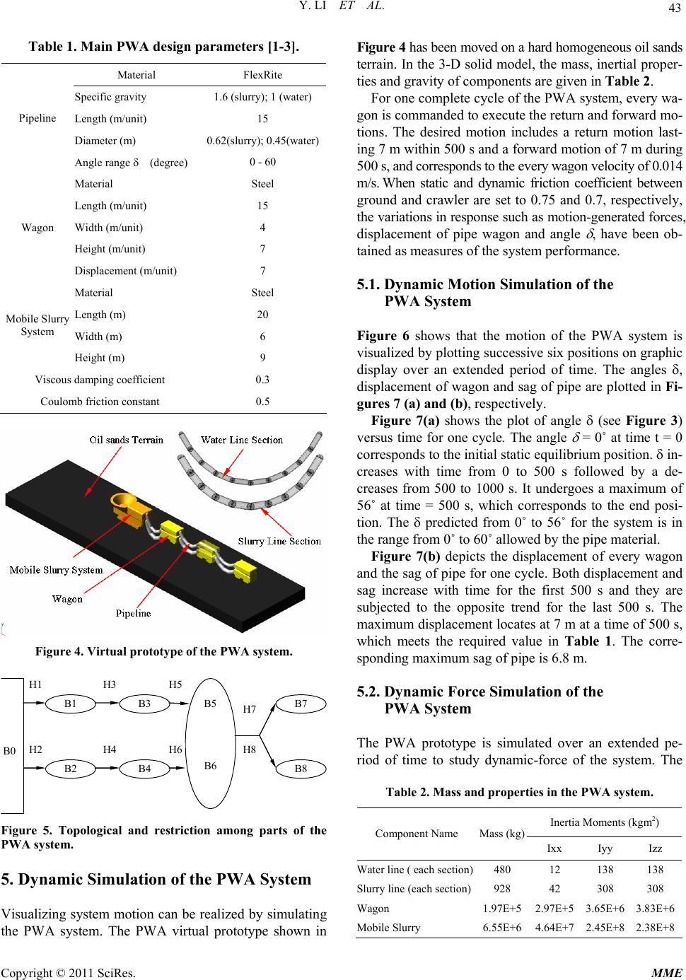 Y. LI ET AL. 43 Table 1. Main PWA design parameters [1-3]. Material FlexRite Specific gravity 1.6 (slurry); 1 (water) Length (m/u ni t ) 15 Diameter (m) 0.62(slurry); 0.45(water) Pipeline Angle range (degree) 0 - 60 Material Steel Length (m/u ni t ) 15 Width (m/unit) 4 Height (m/unit) 7 Wagon Displacement (m/unit) 7 Material Steel Length (m) 20 Width (m) 6 Mobile Slurry System Height (m) 9 Viscous damping coefficient 0.3 Coulomb friction c on s t a n t 0.5 Figure 4. Virtual prototype of the PWA system. B0 B3 B1 B5 B6 B7 B2 B4 B8 H1 H3 H5 H7 H8 H2 H4 H6 Figure 5. Topological and restriction among parts of the PWA system. 5. Dynamic Simulation of the PWA System Visualizing system motion can be realized by simulating the PWA system. The PWA virtual prototype shown in Figure 4 has been moved on a hard homogeneous oil sands terrain. In the 3-D solid model, the mass, inertial proper- ties and gravity of components are given in Table 2. For one complete cycle of the PWA system, every wa- gon is commanded to execute the return and forward mo- tions. The desired motion includes a return motion last- ing 7 m within 500 s and a forward motion of 7 m during 500 s, and corresponds to the every wagon velocity of 0.014 m/s. When static and dynamic friction coefficient between ground and crawler are set to 0.75 and 0.7, respectively, the variations in response such as motion-generated forces , displacement of pipe wagon and angle , have been ob- tained as measures of the system performance. 5.1. Dynamic Motion Simulation of the PWA System Figure 6 shows that the motion of the PWA system is visualized by plotting successive six positions on graphic display over an extended period of time. The angles , displacement of wagon and sag of pipe are plotted in Fi- gures 7 (a) and (b), respectively. Figure 7(a) shows the plot of angle (see Figure 3) versus time for one cycle. The angle = 0˚ at time t = 0 corresponds to the initial static equilibrium position. in- creases with time from 0 to 500 s followed by a de- creases from 500 to 1000 s. It undergoes a maximum of 56˚ at time = 500 s, which corresponds to the end posi- tion. The predicted from 0˚ to 56˚ for the system is in the range from 0˚ to 60˚ allowed by the pipe material. Figure 7(b) depicts the displacement of every wagon and the sag of pipe for one cycle. Both displacement and sag increase with time for the first 500 s and they are subjected to the opposite trend for the last 500 s. The maximum displacement locates at 7 m at a time of 500 s, which meets the required value in Table 1. The corre- sponding maximum sag of pipe is 6.8 m. 5.2. Dynamic Force Simulation of the PWA System The PWA prototype is simulated over an extended pe- riod of time to study dynamic-force of the system. The Table 2. Mass and properties in the PWA system. Inertia Moments (kgm2) Component Name Mass (kg) Ixx Iyy Izz Water line ( each section)480 12 138 138 Slurry line ( each section)928 42 308 308 Wagon 1.97E+5 2.97E+5 3.65E+63.83E+6 Mobile Slurry 6.55E+6 4.64E+7 2.45E+82.38E+8 Copyright © 2011 SciRes. MME 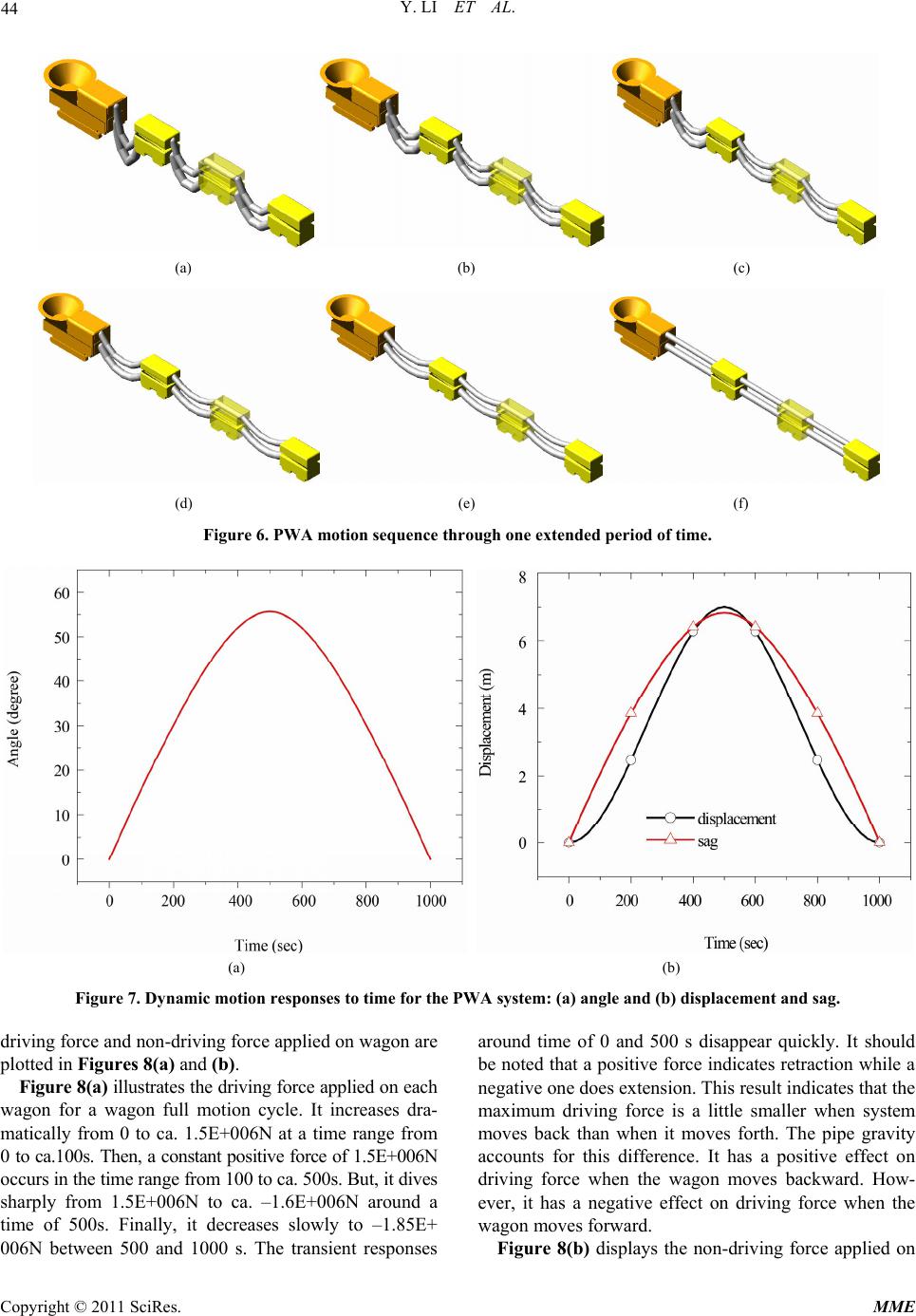 Y. LI ET AL. Copyright © 2011 SciRes. MME 44 (a) (b) (c) (d) (e) (f) Figure 6. PWA motion sequence thr ough one extended period of time. (a) (b) Figure 7. Dynamic motion responses to time for the PWA system: (a) angle and (b) displacement and sag. driving force an d non -d riving fo r ce app lied on w agon are plotted in Figures 8(a) and (b). Figure 8(a) illustrates the driving force applied on each wagon for a wagon full motion cycle. It increases dra- matically from 0 to ca. 1.5E+006N at a time range from 0 to ca.100s. Then, a constant po sitive force of 1.5E+006N occurs in the time range from 100 to ca. 500 s . But, it dives sharply from 1.5E+006N to ca. –1.6E+006N around a time of 500s. Finally, it decreases slowly to –1.85E+ 006N between 500 and 1000 s. The transient responses around time of 0 and 500 s disappear quickly. It should be noted that a p ositive force indicates retraction wh ile a negative one does ex tension. This result indicates that the maximum driving force is a little smaller when system moves back than when it moves forth. The pipe gravity accounts for this difference. It has a positive effect on driving force when the wagon moves backward. How- ever, it has a negative effect on driving force when the wagon moves forward. Figure 8(b) displays the non-driving force applied on 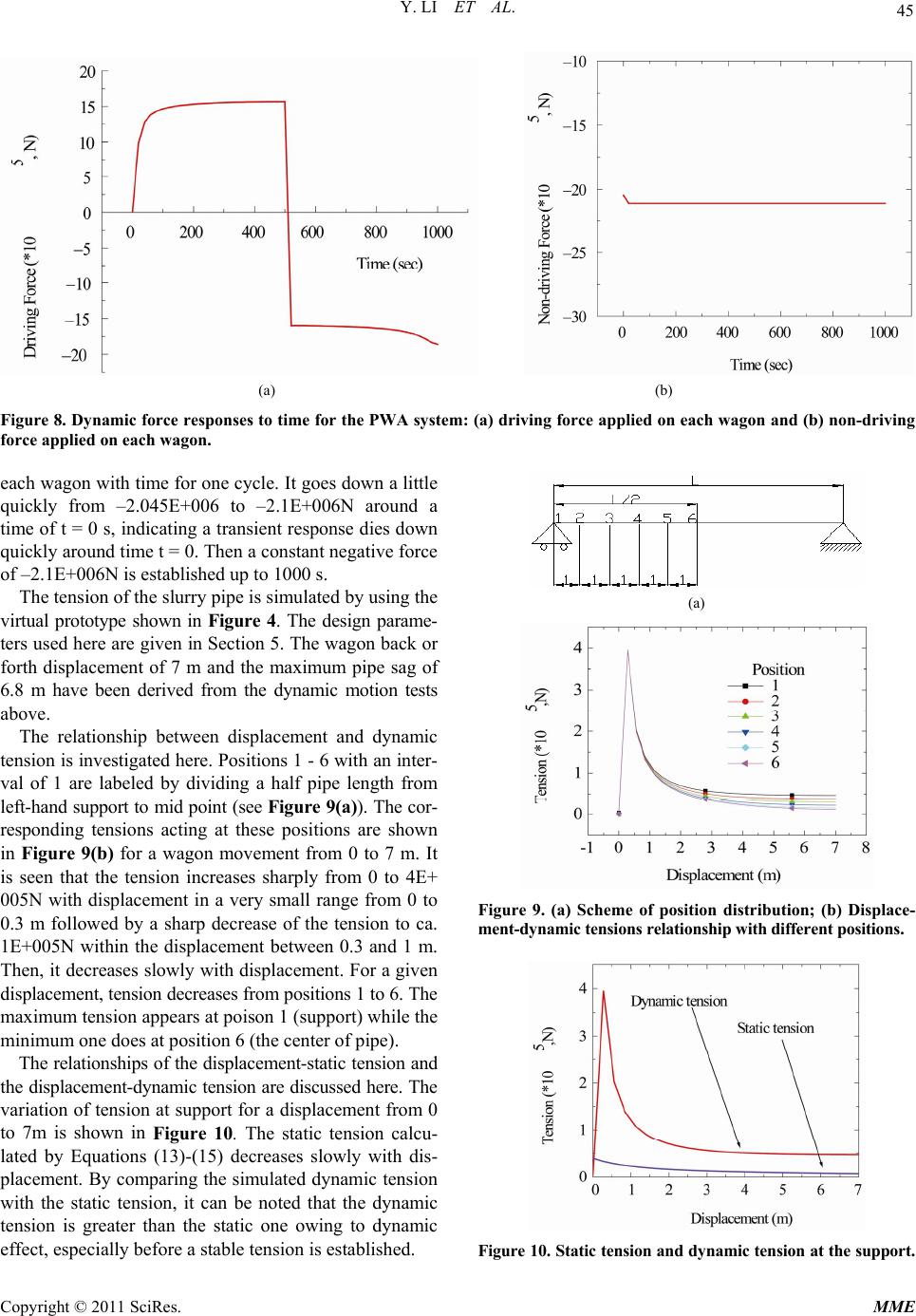 Y. LI ET AL. 45 (a) (b) Figure 8. Dynamic force responses to time for the PWA system: (a) driving force applied on each wagon and (b) non-driving force applied on each wagon. each wagon with time for one cycle. It goes down a little quickly from –2.045E+006 to –2.1E+006N around a time of t = 0 s, indicating a tran sient response dies down quickly around ti me t = 0. Then a constant negativ e force of –2.1E+006N is established up to 1000 s. The tension of the slurry pipe is simulated by using the virtual prototype shown in Figure 4. The design parame- ters used here are given in Section 5. The wagon back or forth displacement of 7 m and the maximum pipe sag of 6.8 m have been derived from the dynamic motion tests above. The relationship between displacement and dynamic tension is investigated here. Po sitions 1 - 6 with an inter- val of 1 are labeled by dividing a half pipe length from left-hand support to mid point (see Figure 9(a)). The cor- responding tensions acting at these positions are shown in Figure 9(b) for a wagon movement from 0 to 7 m. It is seen that the tension increases sharply from 0 to 4E+ 005N with displacement in a very small range from 0 to 0.3 m followed by a sharp decrease of the tension to ca. 1E+005N within the displacement between 0.3 and 1 m. Then, it decreases slowly with displacement. For a given displace ment, tension decreases fro m positions 1 to 6. The maximum tension appears at poison 1 (support) while the minimum one does at position 6 (the center of pipe). The relationshi ps of the displacement-static t ension and the displaceme nt-dynamic tension are discussed here. The variation of tension at support for a displacement from 0 to 7m is shown in Figure 10. The static tension calcu- lated by Equations (13)-(15) decreases slowly with dis- placement. By comparing the simulated dynamic tension with the static tension, it can be noted that the dynamic tension is greater than the static one owing to dynamic effect, especially before a stable tension is established. (a) Figure 9. (a) Scheme of position distribution; (b) Displace- ment-dynamic tensions relationship with different positions. Figure 10. Stati c tension a nd dynamic ten sion at the su pport. Copyright © 2011 SciRes. MME  Y. LI ET AL. 46 6. Conclusions The mechanical system of PWA has been simulated by us ing virtual mo del, which is dev eloped by combinin g the theory of machines and mechanisms and the multi-body dynamic simulation software ADAMS. Important engi- neering data of the PWA system have been determined by simulating reality with a virtual prototype. Th e virtual prototype model of the PWA system has been tested and verified to be effective with real displacement value. The results show this model is capable of kinematics com- puting and offering computer-animated simulations of the kinematics behavior. The results of dynamic-motion ana- lysis indicate that the conceptual designed the PWA sys- tem meets the requirement of the variation of angle from 0˚ to 60˚. The results of dynamic-force simulation have given the maximum force of –1.85E+006N for driving the system and the maximum non-driving force applied on wagon (2.1E+006N) for calculating the bearing ca- pacity of oil sands. The tension analysis of the pipe shows that the distribution of tension along the pipe length is not uniform. The maximum tensi on appears at the support. The result of comparison between the static tension and dyna mic tension illustrates that static tension is much smal- ler than the dy namic tension. This work will allow further benchmarking of the mechanical event simulation of the PWA system s uch as examination of bearing capacity and prediction of pipelin e stress. 7. Acknowledgements The authors wish to express their gratitude to AERI/- COURSE and Syncrude Canada Ltd. for the financial support and field data for this study. 8. References [1] S. Frimpong, R. M. M. Changirwa, E. Asa and J. Szy- manski, “Mechanics of Oil sands Slurry Flow in a Flexi- ble Pipeline System,” International Journal of Surface Mining, Vol. 16, No. 2, 2002, pp. 105-121. doi:10.1076/ijsm.16.2.105.3401 [2] S. Frimpong, O. R. Ayodele and J. Szymanski, “Nu- merical Simulation Software for Oil sands Slurry Flow in Flexible Pipelines,” SCSC 2003 of the Society for Model- ing and Simulation International, Montreal, 20-24 July 2003, pp. 145-154. [3] S. Frimpong, O. R. Ayodele and J. Szymanski, “Numeri- cal Simulator for Oil Sands Slurry Flow in Fle xible Pipe- line,” In proceedings of the 2002 Summer Computer Si- mulation Conference, San Diego, 8-14 July 2002, pp. 171- 176. [4] R. Changirwa, M. C. Rockwell, S. Frimpong and J. Szy- manski, ”Hybrid Simulation for Oil-Solids-Water Separa- tion in Oil Sands Production,” Minerals Engineering, Vol. 12, No. 12, 2002, pp. 1459-1468. doi:10.1016/S0892-6875(99)00134-X [5] S. Frimpong, Y. Li and J. Szymanski, “Mechanical Sys- tem Simulation of the Ground Articulating Pipeline Sys- tem,” Fifteenth IASTED International Conference on Modelling and Simulation, Marina Del Rey, 1-3 March 2004, pp. 209-213. [6] J. E. Shigley and J. J. Uicker, “Theory of Machines and Mechanisms,” McGraw-Hill, New York, 1995. [7] C. E. Wilson and J. P. Sadler, “Kinematics and Dynamics of Machinery,” 2nd Edition, Harper Collins College Pub- lishers, New York, 1991. [8] J. L. Synge and B. A. Griffith, “Principles of Mechanics,” McGraw Hill Book Company, New York, 1959. [9] C. W. Ham, E. J. Crank and W. L. Rogers, “Mechanics of Machinery,” McGraw-Hill, New York, 1958. N. X. Wu, Q. H. Sun, D. L. Yu and Y. A. Pan, “Kinematics Simula- tion and Application for Machine Tool Based on Multi-body System Theory,” Journal of Southeast Uni- versity, Vol. 20, No. 2, 2004, pp. 162-164. [10] N. X. Wu, Q. H. Sun, D. L. Yu and Y. A. Pan, “Kine- matics Simulation and Application for Machine Tool Based on Multi-body System Theory,” Journal of South- east University, Vol. 20, No. 2, 2004, pp. 162-164. [11] H. A. Buchholdt, “An Introduction to Cable Roof Struc- tures,” Thomas Telford, London, 1999. Copyright © 2011 SciRes. MME |