 Energy and Power En gi neering, 2011, 3, 607-615 doi:10.4236/epe.2011.35076 Published Online November 2011 (http://www.SciRP.org/journal/epe) Copyright © 2011 SciRes. EPE RANS and LES Modeling of the GE10 Burner Vladimir L. Zimont1, Vincent Moreu1, Valerio Battaglia1, Roberto Modi2 1CRS4, Science and Technology Park Polaris, Pula, Italy 2GE Oil & Gas Nuovo Pignone, Florence, Italy Recieved April 28, 2011; revised May 29, 2011; acce p ted June 10, 2011 Abstract The paper presents 1) the numerical results of RANS (Reynolds Averaging Navier-Stokes) simulations for two versions of the premixed combustion GE10 burners: the old one with non-premixed and modified one with swirled premixed pilot flames; and 2) the numerical results of joint RANS/LES (Large Eddy Simula- tion) modelling of the ONERA model burner and a simplified GE10 combustor. The original joint RANS/LES approach is based on using the Kolmogorov theory for modelling sub-grid turbulence and com- bustion intensity and using RANS numerical results for closure the LES model equations. The main conclu- sion is that developed joint RANS/LES approch is the efficient timesaving tool for simulations both the av- erage and instantaneous fields of parameters in gas turbine and boiler burners with premixed combustion. Keywords: Turbulent Premixed Combustion, Gas Turbine Burner, Joint RANS/LES Simulation 1. Introduction The proposed work is devoted to lean premixed combus- tion technology, which is nowadays well established within industrial gas turbine industry in order to reduce nitric oxides (NOx) emission. The main numerical mod- eling tool for industrial gas turbine combustion is RANS codes, which yield averaged fields and integral charac- teristics of the flow. The main part of this presentation is devoted to RANS simulations of two variants of the GE10 gas turbine combustor, which include 1) simula- tions of the premixed combustion in the chamber; 2) simulations of the preliminary partial mixing of gas fuel and air; 3) simulations of the non-premixed pilot flame (old version GE10); 4) premixed pilot flame (new ver- sion GE10); and 5) air jets cooling system of the cham- ber. In conditions of industrial gas turbines, instanttane- ous combustion takes place in non-laminar (microturbu- lent) and strongly wrinkled sheets with small-scale structure, which fundamentally cannot be resolved by model RANS and LES equations. In the presented simu- lations, we used our Turbulent Flame Closure (TFC) model [1-3], where this fundamental problem of model- ing (“challenge of turbulent combustion”) is resolved in the context of the Kolmogorov hypothesis of statistical equilibrium of small-scale turbulent structures general- ized for the case of turbulent combustion. This model was already used for RANS simulations of the gas tur- bine combustion and these results where presented in IGTACE, Florida, 1997 (97-GT-395) published in [4] and JPGC, 2001 [5]. (This mode l is now implemented in the commercial codes Fluent and CFX.) RANS results are important but not sufficient as non- stationary characteristics of the flow are also important in gas turbine applications. In academicals works, an attempt to replace RANS tool by LES one is ongoing. We think that “LES instead of RANS” in industrial ap- plication is untimely and we proposed in [6] a joint RANS/LES approach where the mean fields are simu- lated by the RANS tool while the corresponding non- stationary fields are simulated by the LES one using for modeling some information from the preceding RANS simulation. The paper [6 ] contains numerical illustrations of this approach concerning mainly “academic” flames. We achieved agreement between RANS and LES sub- problems by using in fact the same combustion models in both sub-problems. In this paper, we present numerical results in the context of the joint RANS/LES approach for gas turbine com b us tors. We found support to our approach in the invited lec- ture [7]. In the conclusions, the authors write: “The fu- ture tools for gas turbine designs will be based on classi- cal Reynolds Averages codes to predict main flows but will also rely on Large Eddy Simulation tools coupled to acoustic codes” (in our example both RANS and LES sub-problems were stated in incompressible formulation).  V. L. ZIMONT ET AL. 608 We notice that proposed in this paper approach was dis- cussed at the ASME ATI Conference in Italy “Energy: production, distribution and conservation” in May, 2006 and was submitted to the proceeding of the conference, but it was not published in a journal. We use this joint RANS/LES approach in our work with the industries and hope that this publication would be useful for engineers working in the field modeling of industrial combustion. 2. Principles of Modelling and the Equations In this section we briefly describe a physical model of premixed combustion at strong turbulence and fast chemistry and present the equations used for both RANS and LES simulations. 2.1. The Physical Model In gas turbines, typical turbulent Reynolds numbers RetuL are large and typical Damkohler numbers tch Da are moderately large. Here, tLu and 2 ch L S are the turbulent and chemical times, is the molecular heat conductivity and S is the speed of the normal laminar flame, these parameters being used in the model as the physico-chemical characteristics of the reactant. In this case, the speed U and width of the thickened flamelets are controlled by the statistically equilibrium small-scale turbulence and the chemical time t , and it results the following expressions [1-3]: 12 32 ,. Lf L UuDaSL Da (1) The flamelet broadening takes place at43 Re Lt L , i.e. when the size of the minimal eddies is less than the laminar flame width . At the same time, the thic- kened flamelet sheet is strongly wrinkled by turbulence when L and hence the condition for this combus- tion mechanism is the following [1-3]: 3232 43 1Re t DaDa (2) So the mod el is val id at and ; these conditions are common for large-scale gas turbine combustors. For weaker turbulence, common for small- scale laboratory burners, instantaneous turbulent com- bustion takes place in a wrinkled laminar flamelet sheet. Real combustion takes place in transient flames with increasing width. The reason is that the large-scale wrin- kles of the flamelet sheet remain statistically in non-equi- librium at real residence time in the combustor. So the width is controlled by the turbulent diffusion coefficient t quite similarly to the nonreacting mixing layer. At the same time, the small-scale winkles can be assumed statistically in equilibriu m and as they give the main con- tribution in the dimensionless flamelet sheet area 23 Re(10-10 ) t1 10Da D 0, Fthe turbulent flame velocity 0tf UUFF is controlled by large-scale turbulence parameters (in the model, they are the r.m.s. velocity pulsation u and the integral scale ) and the chemical time L 14 : tt UuDa [1-3]. 2.2. RANS Equations of the TFC Premixed Combustion Model We analyze premixed flames adopting the flamelet for- malism in terms of the progress variable c, using the known bimodal approximation of the PDF p(c) where the width of the thin instantaneous reaction zone is ignored. In this case, we have the following expressions: 1 ,, 11 1, 1, uub ub iiu ib c TTc Tc CC cCc , (3) where , ,, uu iu TC and , ,, bb ib TC are the density, temperature and species concentrations in unburned (re- actants 0c ) and burned (equilibrium products 1c ) gases. The turbulent combustion front, moving with speed Ut and having increasing brush width controlled by Dt, is described by the following transport equations: 341212 14 (), (), tut tLu ct c DcU ca UuS Lb u (4) where is an empirical constant equal to 0.5 H valid for all fuels tested in [8,9] (methane 4, ethane 26 , propane 38 and even for hydrogen 2). Equations (4) are combined with the average hydrody- namic equations and the “ CH CH CH -k ” model. 2.3. The LES Equations of the TFC Model The main idea of our joint RANS/LES approach [6] is to combine LES and RANS in a two-stage process. The first step consists of the RANS simulation which yields the averaged flow field; the second step entails LES us- ing the mean turbulent dissipation rate (,) t obtained from RANS to estimate the subgrid turbulence u and subgrid flame speed 0tf. LES gives non- stationary images of a RANS simulation. UUFF The model LES equation can be cast as follows: ut ct uc DcUc (5) Copyright © 2011 SciRes. EPE 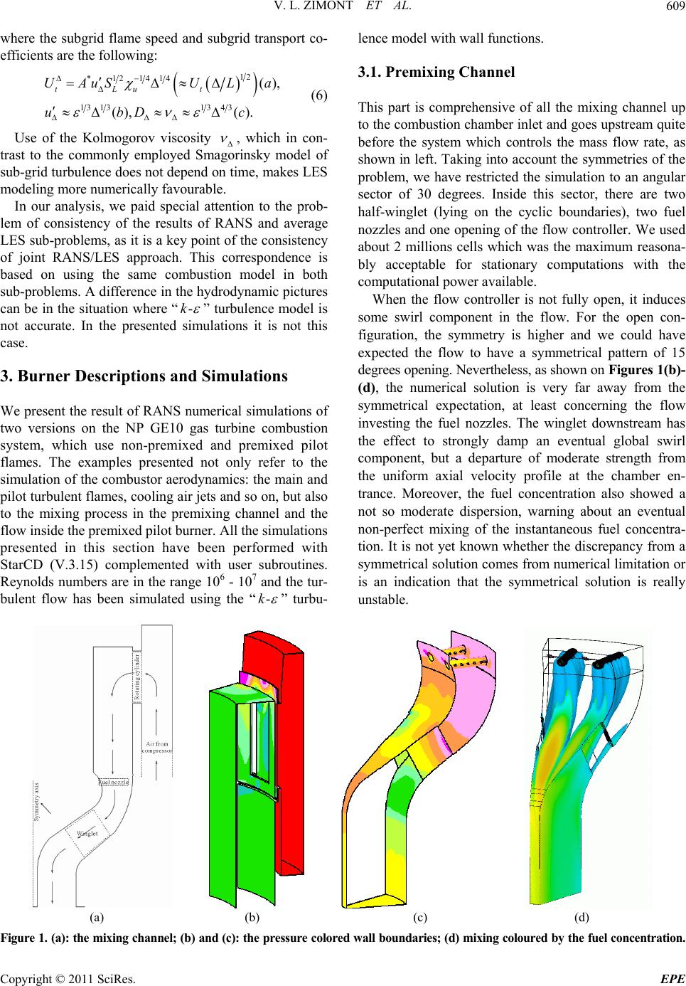 V. L. ZIMONT ET AL. Copyright © 2011 SciRes. EPE 609 lence model with wall functions. where the subgrid flame speed and subgrid transport co- efficients are the following: 3.1. Premixing Channel 12 *121414 13 131343 (), (), (). tLu t UAuSU La ubD c (6) This part is comprehensive of all the mixing channel up to the combustion chamber inlet and goes upstream quite before the system which controls the mass flow rate, as shown in left. Taking into account the symmetries of the problem, we have restricted the simulation to an angular sector of 30 degrees. Inside this sector, there are two half-winglet (lying on the cyclic boundaries), two fuel nozzles and one openin g of the flow controller. We used about 2 millions cells which was the maximum reasona- bly acceptable for stationary computations with the computational power a vailable. Use of the Kolmogorov viscosity , which in con- trast to the commonly employed Smagorinsky model of sub-grid tu rbulen ce does not dep end on time, makes LES modeling more numerically favourable. In our analysis, we paid special attention to the prob- lem of consistency of the results of RANS and average LES sub-problems, as it is a key point of the consistency of joint RANS/LES approach. This correspondence is based on using the same combustion model in both sub-problems. A difference in the hydrodynamic p ictures can be in the situation where “-k ” turbulence model is not accurate. In the presented simulations it is not this case. When the flow controller is not fully open, it induces some swirl component in the flow. For the open con- figuration, the symmetry is higher and we could have expected the flow to have a symmetrical pattern of 15 degrees opening. Nevertheless, as shown on Figures 1(b)- (d), the numerical solution is very far away from the symmetrical expectation, at least concerning the flow investing the fuel nozzles. The winglet downstream has the effect to strongly damp an eventual global swirl component, but a departure of moderate strength from the uniform axial velocity profile at the chamber en- trance. Moreover, the fuel concentration also showed a not so moderate dispersion, warning about an eventual non-perfect mixing of the instantaneous fuel concentra- tion. It is not yet known whether the discrepancy from a symmetrical solution comes from numerical limitation or is an indication that the symmetrical solution is really unstable. 3. Burner Descriptions and Simulations We present the result of RANS numerical simulations of two versions on the NP GE10 gas turbine combustion system, which use non-premixed and premixed pilot flames. The examples presented not only refer to the simulation of the combustor aerodynamics: the main and pilot turbulent flames, cooling air jets and so on, but also to the mixing process in the premixing channel and the flow inside the premixed pilot burner. All the simulations presented in this section have been performed with StarCD (V.3.15) complemented with user subroutines. Reynolds numbers are in the range 106 - 107 and the tur- bulent flow has been simulated using the “- k ” turbu- (a) (b) (c) (d) Figure 1. (a): the mixing channel; (b) and (c): the pressure colored wall boundaries; (d) mixing coloured by the fuel concentration. 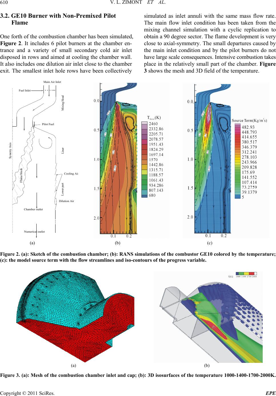 V. L. ZIMONT ET AL. Copyright © 2011 SciRes. EPE 610 3.2. GE10 Burner with Non-Premixed Pilot Flame One forth of the combustion chamber has been simulated, Figure 2. It includes 6 pilot burners at the chamber en- trance and a variety of small secondary cold air inlet disposed in rows and aimed at cooling the chamber wall. It also includes one dilution air inlet close to the chamber exit. The smallest inlet hole rows have been collectively simulated as inlet annuli with the same mass flow rate. The main flow inlet condition has been taken from the mixing channel simulation with a cyclic replication to obtain a 90 degree sector. The flame development is very close to axial-symmetry. The small departures caused by the main inlet condition and by the pilot burners do not have large scale consequences. Intensive combustion takes place in the relatively small part of the chamber. Figure 3 shows the mesh and 3D field of the temperature. Chamber outlet Numerical outlet Cooling A Dilution Air Pilot Fuel Fuel Inlet Mixing HeadLiner Lower part Flame brush (a) (b) (c) Figure 2. (a): Sketch of the combustion chamber; (b): RANS simulations of the combustor GE10 colored by the temperature; (c): the model source term with the flow streamlines and iso-contours of the progress variable. (a) (b) F igure 3. (a): Mesh of the combustion chamber inlet and cap; (b): 3D isosurfaces of the temperature 1000-1400-1700-2000K.  V. L. ZIMONT ET AL. Copyright © 2011 SciRes. EPE 611 3.3. GE10 Combustor with Premixed Pilot Flame To lower to NOx formation, GE decided to test a variant of the combustor where the 24 non-premixed pilot burn- ers were replaced by 4 bigger but essentially premixed pilot burners. This procedure allowed having less fuel burnt in stochiometric condition. The pilot burner has been numerically tested in stand-alone condition. Figure 4, left, shows the fuel concentration that remains high only on a very narrow central region in exit of the burner. In Figure 4, centre, we see how the flame develops on an axial plane. Figure 4, right, show the n ew pilot burn er as been numerically tested inserted in the combustion chamber cap. The global reacting flow field is somehow disturbed by the presence of the new pilot, Figure 5, and, obviously, is not any more close to axial-symmetrical. Mainly, the recirculation region is heavily perturbed as it is shown on Figure 6, left and centre. The interaction of the hotter pilot flame with the colder main flame can be appreciated in Figure 6, right. 4. Joint RANS/LES Modelling of Turbulent Premixed Gas Turbine Combustion To understand the non- statio nary features of the flow, we performed a LES analysis of the burner. We used our Joint RANS/LES approach [6] that strongly shortens the LES analysis. The simulations were performed using the Fluent package, a finite volume code which gives the possibility to customize the models implemented. It has a second order centered scheme fit to LES simulations which require low dissipative numerical schemes. In the next paragraphs, we present the validation of this approach for a standard test case and then we show results of the LES for a simplified geometry of the GE burner previously described, not considering pilot system and cooling jets. 4.1. The ONERA Standard Burner To validate the Joint RANS/LES approach, we used a standard test case known as the Moreau (ONERA) burner [10]. It consists in a rectangular section burner with the flame stabilized by a burned gas flow. The fuel is a methane-air mixture with equivalence ratio equal to 0.84. The flow structures is mainly 2D due to the high aspect ratio of the cross section, so it is possible to per- form 2D simulations without losing accuracy in the re- sults. In this test case, LES simulations are very sensitive to inlet boundaries conditions for turbulence; in the pre- sent work, we introduced a disturbance in the average inlet velocity derived by the amplitude and length of the upstream flow turbulent characteristics reported in [10]. The results of both RA NS and LES approac hes, Figure 7, show that the turbulent premixed flame has increasing brush widt h and at the sam e time nearly co nstant speed, as it can be seen by the practically constant angle with re- spect to the main flow. In the figure measured in the ex- periment mean temperature T and velocity U, and the turbulent param eters (the rms fl uctuation of the velocity u' and the integral scale L) have indexes “u” and “b” that refer correspondingly to the flows of the unburned and burned gases at the entrance of the burner. The upper graph represents a result of the RANS simulation of the progress variable : five isolines and two profiles in the sections x = 0.1 and x = 0.5. The lower graph represent the LES results: five isolines of the i nstantaneous progress variable and following from averaging of the LES result mean profiles for x = 0.1 and x = 0.5 and isolines of the mean progress variables. c c The isolines, which directly follow from LES model- ing, clearly show the instantaneous stru cture of the flame with the effects of the large scale vortices that convoluted Figure 4. Left: premixed pilot burner with 2 coaxial swirling flows, coloured by the fuel concentration, the external flow ar- rives already mixed in the burning region and only the central part keeps a high fuel concentration; center: pilot burner flame with streamlines coloured by temperature; right: the computational mesh of the combustion chamber cap with the ilot burner inserted. p  V. L. ZIMONT ET AL. Copyright © 2011 SciRes. EPE 612 perature are not available to verify the accuracy of the fluctuations resulting from the simulations, but observed agreement between R ANS and a verage LE S data is a clue of the reliability of the instantaneous data. Figure 5. Field of equivalence ratio Φ with stream lines in a section of the burner. The lower graph in Figure 7 represent also a linear distribution of a passive concentration z in the entrance section x = 0, which was used in the simulations as a boundary condition, and following from averaging of the LES results the mean profilesin the section x = 0.1 and x = 0.5. Performed in [6] comparative analysis of the LES data for the progress variableand the passive con- centrations z showed that in the flame the mean flux of the passive concentration z is gradient, while the mean flux of the progress variable c is predominantly counter- gradient: it is gradient in the beginning of the flame and then becomes counter-gradient in the main part of the flame. The reason is that the flux of the passive concen- z c and stretched the isosurfaces inside the flame. Compari- son of the mean isolines and the profiles of the progress variables simulated directly by the RANS simulation and by averaging of the LES data (the uppe r a nd lower gra phs in Figure 7) are similar. Figure 8 shows that the mean profiles of the progress variable and the velocity, which follow from the RANS and LES approaches, are close and they are in reasonable agreement with the experimental data from [10]. Measurements of r.m.s. velocity or tem- Figure 6. Left: combustion chamber surface temperature. Centre: global flow temperature in the combustion chamber, trace effects of the pilot burner, the cooling inlet rows and the dilution hole can be appreciated. Right: flow temperature and streamlines on the plane containing the chamber and the pilot burner axes. Inlet: T u = 600K U u = 60 m/s T b = 2200 K U b = 120 m/s RANS X(m) 1 0.50 0 0.1 y(m) U c = 0.1 c = 0.3 c = 0.5 c = 0.7 c = 0.95 0c 0.1 c 0.5 c y(m) (a) CH 4 +air = 0.8 u U = 8 m/s L u = 5.4 mm b U = 23 m/s L b = 1.6 mm LES X(m) 1 0.5 0 0 0.1 0.1 c 0.5 c y(m) 0.1 0 (b) Figure 7. Average and instantaneous field of progress variable (a): RANS simulation, (b) corresponding LES.  V. L. ZIMONT ET AL.613 Figure 8. Comparison of axial velocity (left) and temperature (right) with experimental data. tration is controlled only by turbulent diffusion, while the flux of the progress variable is controlled by turbulence and the gasdynamic mechanism: different pressure-dri- ven acceleration in the flame of relatively heavy reac- tants and light products. The balance between turbulent and gasdynamic mechanisms controls observed in the premixed flame transition from gradient to counter-gra- dient flux of the reacting c. It is to remark that LES de- scribe this transition without any additional model [6]. In the RANS version of the TFC model we overcame this problem by including of the gasdynamic contribution in the model chemical source [2]. So the transport term in Equation (4) is controlled only by gradient turbulent dif- fusion and hence there is no need to model in practical simulation the counter-gradient transport phenomenon. 4.2. Simplified Version of the GE10 Combustor To test the Joint RANS/LES approach, we performed LES of a simplified geometry of the first version of the GE burner previously described (the cooling jets and the pilot system were not meshed). We used Fluent code and simulated a 60˚ degree section of the burner applying periodic boundary condition at the lateral sections. LES average shows good agreement with RANS data. The non-stationary images of the flow field give an idea of the effects of large scale vortices on the flame displace- ments. In Figure 9(a) RANS and instantaneous LES progress variable are overlapping on a section of the burner to show the convolu tion of the instantaneous reactin g zone, which travels and is stretched by vortex shedding from the geometrical step. Figure 9(b) clearly shows the tur- bulent structure originated at the inlet step and how they evolve along the flow. LES gives the possibility to un- derstand the trend of variation of the flame shape chang- ing operative conditions and boundary conditions. It is possible to create 3D visualizations to see the effects of the vortex structures in the circumferential direction as shown in Figure 10. Our joint RANS/LES approach, obviously, does not exclude the possibility to use LES modeling, that is independent on the RANS one and based on using common now Smagorinsky model of the sub-grid viscosity. In this connection, we would like to mention the paper [11], which is devoted to the com- parison of predictions of the premixed flame anchoring in the double cone gas turbine burner using independent RANS and LES approaches based on our TFC combus- tion model. We notice only that our joint RANS/LES approach permits to reduce significantly computation time of LES. 5. Conclusions The presented results consist of two parts: 1) Comprehensive (wherever possible) RANS nume- rical simulations of aerodynamic systems of two versions of the GE10 gas turbine combustor (with nonpremixed and swirled premixed pilot flames): cold mixing cham- bers of the combustor and the premixed pilot burner, aerodynamic of the main and pilot flames together with an actual system of air cooling jets. 2) Numerical illustrations of our original joint RANS/ LES approach applied to the gas turbine combustion (using the standard model situation and a simplified ver- sion of the GE10 combustor), which can be an effective and economical tool for the analysis of both stationary mean and nonstationary fields of parameters. All simulations where performed in the context of the TFC combustion model, which, in particular yielded reasonable agreement between RANS and LES sub- problems. Our general conclusion is that RANS simulations re- Copyright © 2011 SciRes. EPE  V. L. ZIMONT ET AL. 614 (a) (b) Figure 9. 2D visualization of middle-section. (a): Contour lines of progress variable (from 0.1 to 0.9 step 0.2) for RANS (brown) and instantaneous LES (blue); (b); (b) iso-surfaces of LES and the field of the vorticity. Figure 10. 3D visualization. Two isosurfaces of the progress variable (left) and the field of the vorticity (right). main a necessary (but not sufficient) tool for practical numerical analysis of the gas turbine premixed combus- tion and the joint RANS/LES approach can be a useful tool for investigation of non-stationary characteristics of Copyright © 2011 SciRes. EPE  V. L. ZIMONT ET AL.615 the flow, including unsteady combustion regimes. It seems that complete replacement of the RANS tool by the LES one is untimely at least for gas turbine applica- tions. 6. References [1] V. L. Zimont, “A Theory of Turbulent Pre mixed Combus- tion at High Reynolds Numbers,” Combustion, Explosion, and Shock Waves, Vol. 15, No. 3, 1979, pp. 305-311. doi:10.1007/BF00785062 [2] V. L. Zimont, “Gas Premixed Combustion at High Tur- bulence. Turbulent Flame Closure Combustion Model,” Experimental Thermal and Fluent Science, Vol. 21, No. 1-3, 2000, pp. 179-186. doi:10.1016/S0894-1777(99)00069-2 [3] V. Zimont, “Kolmogorov’s Legacy and Turbulent Pre- Mixed Combustion Modelling,” In: W. J. Carey, Ed., New Developments in Combustion Research, Nova Science Publishers, New York, 2006, pp. 1-93. [4] V. Zimont, W. Polifke, M. Bettelini and W. Weisenstein, “An Efficient Computational Model for Premixed Turbu- lent Combustion at High Reynolds Numbers Based on a Turbulent Flame Speed Closure,” Journal of Engineering for Gas Turbines and Power (Transactions of the ASME), Vol. 120, No. 3, 1998, pp. 526-532. doi:10.1115/1.2818178 [5] V. Biagioli, L. Zimont and K. J. Sy ed “Modelling and Nu- merical Simulation of Turbulent Combustion in DLE Burners Based on a Turbulent Flame Speed Approach,” International Joint Power Generation Conference, New Orleans, 4-7 June 2001, pp. 1-14. [6] V. L. Zimont and V. Battaglia, “Joint RANS/LES Ap- proach to Premixed Flame Modelling in the Context of the TFC Combustion Model, Flow, Turbulence and Com- bustion”, Vol. 77, No. 1-4, 2006, pp. 305-331. [7] T. Poinsot and L. Selle, “LES and Acoustic Analysis of Combustion Instabilities in Gas Turbine,” Plenary Lec- tures ECCOMAS—Computational Combustion Sympo- sium, Lisbon, 21-24 June 2005. [8] V. L. Zimont and A. N. Lipatnikov, “A Numerical Model of Premixed Turbulent Combustion of Gases,” Chemical Physics Reports, Vol. 14, No. 7, 1995, pp. 993-1025. [9] V. P. Karpov, A. N. Lipatni kov and V. L. Zi mont, “Te st of the Engineering Premixed Combustion Model,” Sympo- sium (International) on Combustion, Vol. 26, No. 1, 1996, pp. 249-261. [10] P. Moreau, “Turbulent Flame Development in a High Velocity Premixed Flow,” American Institute of Aero- nautics and Astronautics, Aerospace Sciences Meeting, Los Angeles, 24-26 January 1977. [11] F. Biagioli, “Stabilization Mechanism of Turbulent Pre- Mixed Flames in Strongly Swirled Flows,” Combustion Theory and Modelling, Vol. 10, No. 3, 2006, pp. 389-412. doi:10.1080/13647830500448347 Copyright © 2011 SciRes. EPE
|

