

Paper Menu >>
Journal Menu >>
 Energy and Power En gi neering, 2011, 3, 593-599 doi:10.4236/epe.2011.35074 Published Online November 2011 (http://www.SciRP.org/journal/epe) Copyright © 2011 SciRes. EPE An Investigation into Substation Grounding and Its Implementation on Gaza Substation Ahmed Hammuda1, Hassan Nouri1, Mohammed Saleh Al-Ayoubi2 1Department of Engineering Design and Mathematics, University of the West of England, Bristol, United Kingdom 2Faculty of Mechanical & Electrical Engineering, University of Damascus, Damascus, Syria Recieved October 2, 2011; revised November 10, 2011; accepted November 18, 2011 Abstract An investigation into the optimal design of a substation grounding system for the transmission substation in Gaza City, Palestine has been carried out. A research into the most influential parameters on the effective- ness of the substation grid system has been performed and its results have been incorporated into the Gaza case study. Through modelling and simulating the power station in Gaza while considering some field data, an optimal substation grounding grid has been designed and has shown complete conformance to safety. It is thus considered that such a design will protect personnel in any area of the substation in addition to the in- stalled machinery if the largest possible fault current was to traverse the earth. Keywords: Gaza, Grounding Grid, Ground Resistance, Substation, Step Voltage, Touch Voltage 1. Introduction Grounding is by far one of the most imperative aspects of electrical systems design the significance of which has attained modest mention. The design of the substation is complex and constitutes a copious number of interlinked factors that all need taking into account. A substation grounding system is an underground, regular mesh con- ductor network that serves the purpose of providing the path of least resistance to the traversing current so that in the case of a fault it is distributed in all directions of the underlying earth. If efficient, the resulting ground poten- tial due to a fault and the ensuing touch and step voltages will be low enough to guarantee the safety of personnel working on the substation in addition to safety of the installed machinery. This paper research investigates the effects of altering certain parameters on the effectiveness of the grounding system, focusing on the most relevant parameters before applying the findings of the investigation on the substa- tion of the Gaza Power Generating Company in Gaza City, Palestine. The selection of this case study is due to the intrinsic characteristics of the substation earth being sandy and in close proximity to the sea, and for this rea- son, at least the accessible top layers will be of consid- erably high resistivity. Additionally, the power station being the only one locally generating power exhibits a substantial fault current in such a case. The substantial necessity to protect the personnel and the dependable machinery stipulates the design of a completely trust- worthy and effective grounding system exhibiting touch and step voltages within tolerable margins. Seeing as the ground resistance g R is a major deter- minant of the system safety, it becomes of interest to study parameters that aid in reducing this quantity. It should be noted that a low ground resistance does not necessitate an even distribution of surface potentials across the grid thus it becomes necessary to study some parameters that help to regulate surface voltages. For this parametric analysis and for the corresponding design pertaining to Gaza substation, the grounding grid analy- sis module in ETAP is utilised. While to determine the fault current that can potentially be available at Gaza power station, PSCAD is used. 2. Ground Potential Rise, Touch Voltage and Step Voltage 2.1. Ground Potential Rise The ground potential rise (GPR) is the product of the ground resistance g R which is a function of the number of grid conductors, its area, its depth and the resistivity of the surrounding soil multiplied by the current G I entering the grid during a fault [1]. 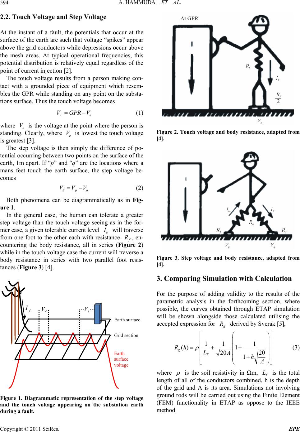 A. HAMMUDA ET AL. 594 e q 2.2. Touch Voltage and Step Voltage At the instant of a fault, the potentials that occur at the surface of the earth are such that voltage “spikes” appear above the grid conductors while depressions occur above the mesh areas. At typical operational frequencies, this potential distribution is relatively equal regardless of the point of current injection [2]. The touch voltage results from a person making con- tact with a grounded piece of equipment which resem- bles the GPR while standing on any point on the substa- tions surface. Thus the touch voltage becomes T VGPRV (1) where e is the voltage at the point where the person is standing. Clearly, where is lowest the touch voltage is greatest [3]. V e V The step voltage is then simply the difference of po- tential occurring between two points on the surface of the earth, 1m apart. If “p” and “q” are the locations where a mans feet touch the earth surface, the step voltage be- comes Sp VVV (2) Both phenomena can be diagrammatically as in Fig- ure 1. In the general case, the human can tolerate a greater step voltage than the touch voltage seeing as in the for- mer case, a given tolerable current level b I will traverse from one foot to the other each with resistance f R, en- countering the body resistance, all in series (Figure 2) while in the touch voltage case the current will traverse a body resistance in series with two parallel foot resis- tances (Figure 3) [4]. Earth surface Grid section Earth surface voltage I f V s Vt Figure 1. Diagrammatic representation of the step voltage and the touch voltage appearing on the substation earth during a fault. Figure 2. Touch voltage and body resistance, adapted from [4]. Figure 3. Step voltage and body resistance, adapted from [4]. 3. Comparing Simulation with Calculation For the purpose of adding validity to the results of the parametric analysis in the forthcoming section, where possible, the curves obtained through ETAP simulation will be shown alongside those calculated utilising the accepted expression for g R derived by Sverak [5], 11 1 () 1 20 20 1 gT Rh LAhA (3) where is the soil resistivity in Ωm, T is the total length of all of the conductors combined, h is the depth of the grid and A is its area. Simulations not involving ground rods will be carried out using the Finite Element (FEM) functionality in ETAP as oppose to the IEEE method. L Copyright © 2011 SciRes. EPE 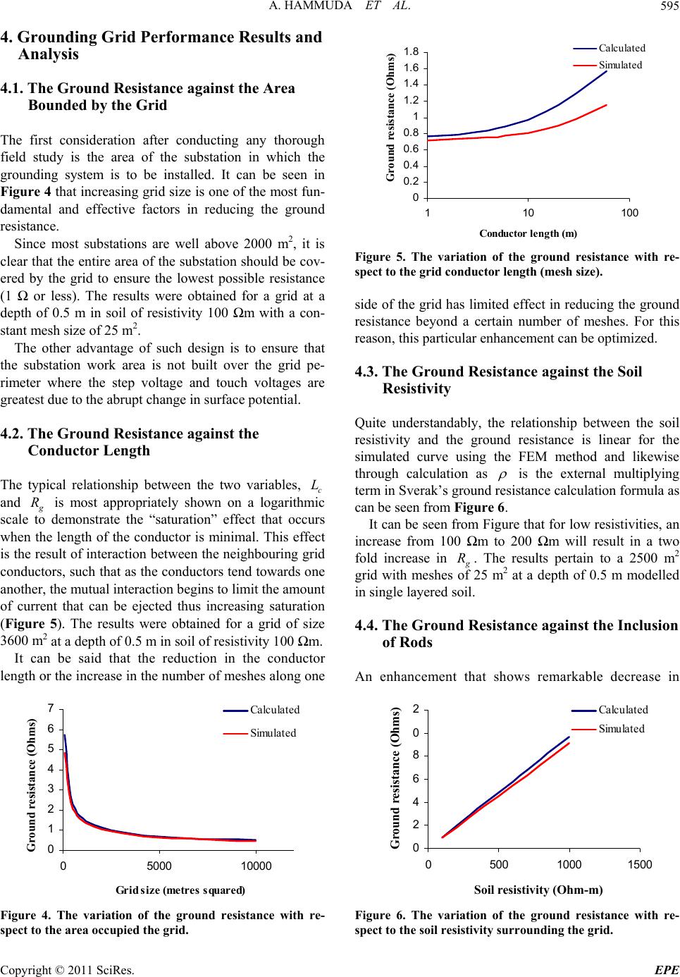 A. HAMMUDA ET AL.595 4. Grounding Grid Performance Results and Analysis 4.1. The Ground Resistance against the Area Bounded by the Grid The first consideration after conducting any thorough field study is the area of the substation in which the grounding system is to be installed. It can be seen in Figure 4 that increasing grid size is one of the most fun- damental and effective factors in reducing the ground resistance. Since most substations are well above 2000 m2, it is clear that the entire area of the substation should be cov- ered by the grid to ensure the lowest possible resistance (1 Ω or less). The results were obtained for a grid at a depth of 0.5 m in soil of resistivity 100 Ωm with a con- stant mesh size of 25 m2. The other advantage of such design is to ensure that the substation work area is not built over the grid pe- rimeter where the step voltage and touch voltages are greatest due to the abrupt change in surface potential. 4.2. The Ground Resistance against the Conductor Length The typical relationship between the two variables, c and L g R is most appropriately shown on a logarithmic scale to demonstrate the “saturation” effect that occurs when the length of the conductor is minimal. This effect is the result of interaction between the neighbouring grid conductors, such that as the conductors tend towards one another, the mutual interaction begins to limit the amount of current that can be ejected thus increasing saturation (Figure 5). The results were obtained for a grid of size 3600 m2 at a depth of 0.5 m in soil of resistivity 100 Ωm. It can be said that the reduction in the conductor length or the increase in the number of meshes along one 0 1 2 3 4 5 6 7 05000 10000 Grid size (metres squared) Calculated Simulated Ground resistance (Ohms) Figure 4. The variation of the ground resistance with re- spect to the area occupied the grid. Ground resistance ( Ohms ) 0 0.2 0.4 0.6 0.8 1 1.2 1.4 1.6 1.8 110 100 Conductor length (m) Calculated Simula te d Figure 5. The variation of the ground resistance with re- spect to the grid conductor length (mesh size). side of the grid has limited effect in reducing the ground resistance beyond a certain number of meshes. For this reason, this particular enhancement can be optimized. 4.3. The Ground Resistance against the Soil Resistivity Quite understandably, the relationship between the soil resistivity and the ground resistance is linear for the simulated curve using the FEM method and likewise through calculation as is the external multiplying term in Sverak’s ground resistance calculation formula as can be seen from Figure 6. It can be seen from Figure that for low resistivities, an increase from 100 Ωm to 200 Ωm will result in a two fold increase in g R. The results pertain to a 2500 m2 grid with meshes of 25 m2 at a depth of 0.5 m modelled in single layered soil. 4.4. The Ground Resistance against the Inclusion of Rods An enhancement that shows remarkable decrease in 0 2 4 6 8 10 12 05001000 1500 Soil resistivity (ohm-m) Ground resistance (ohms ) Calculated Simulated Ground resistance (Ohms) Soil resistivity (Ohm-m) Figure 6. The variation of the ground resistance with re- spect to the soil resistivity surrounding the grid. Copyright © 2011 SciRes. EPE 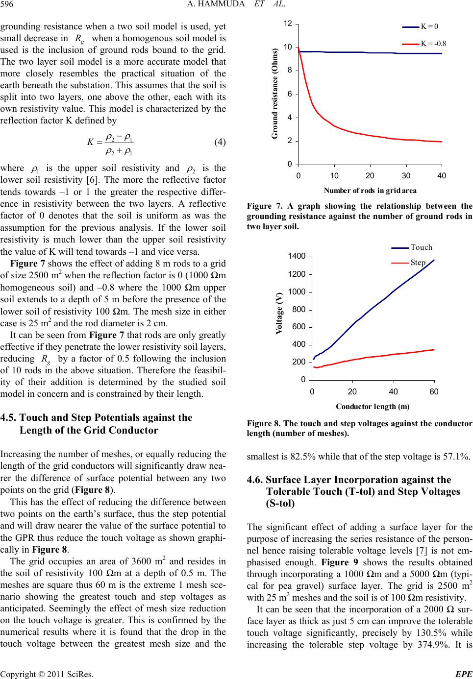 A. HAMMUDA ET AL. 596 grounding resistance when a two soil model is used, yet small decrease in g R when a homogenous soil model is used is the inclusion of ground rods bound to the grid. The two layer soil model is a more accurate model that more closely resembles the practical situation of the earth beneath the substation. This assumes that the soil is split into two layers, one above the other, each with its own resistivity value. This model is characterized by the reflection factor K defined by 21 21 K (4) where 1 is the upper soil resistivity and 2 is the lower soil resistivity [6]. The more the reflective factor tends towards –1 or 1 the greater the respective differ- ence in resistivity between the two layers. A reflective factor of 0 denotes that the soil is uniform as was the assumption for the previous analysis. If the lower soil resistivity is much lower than the upper soil resistivity the value of K will tend towards –1 and vice versa. Figure 7 shows the effect of adding 8 m rods to a grid of size 2500 m2 when the reflection factor is 0 (1000 Ωm homogeneous soil) and –0.8 where the 1000 Ωm upper soil extends to a depth of 5 m before the presence of the lower soil of resistivity 100 Ωm. The mesh size in either case is 25 m2 and the rod diameter is 2 cm. It can be seen from Figure 7 that rods are only greatly effective if they penetrate the lower resistivity soil layers, reducing g R by a factor of 0.5 following the inclusion of 10 rods in the above situation. Therefore the feasibil- ity of their addition is determined by the studied soil model in concern and is constrained by their length. 4.5. Touch and Step Potentials against the Length of the Grid Conductor Increasing the number of meshes, or equally reducing the length of the grid conductors will significantly draw nea- rer the difference of surface potential between any two points on the grid (Figure 8). This has the effect of reducing the difference between two points on the earth’s surface, thus the step potential and will draw nearer the value of the surface potential to the GPR thus reduce the touch voltage as shown graphi- cally in Figure 8. The grid occupies an area of 3600 m2 and resides in the soil of resistivity 100 Ωm at a depth of 0.5 m. The meshes are square thus 60 m is the extreme 1 mesh sce- nario showing the greatest touch and step voltages as anticipated. Seemingly the effect of mesh size reduction on the touch voltage is greater. This is confirmed by the numerical results where it is found that the drop in the touch voltage between the greatest mesh size and the 0 2 4 6 8 10 12 010203040 Number of rods in grid area Ground resistance (ohms ) K = 0 K = -0.8 Ground resistance (Ohms) Figure 7. A graph showing the relationship between the grounding resistance against the number of ground rods in two layer soil. 0 200 400 600 800 1000 1200 1400 020406 Conductor length (m) Voltage (v 0 ) To u ch Step Voltage (V) Figure 8. The touch and step voltages against the conductor length (number of meshes). smallest is 82.5% while that of the step voltage is 57.1%. 4.6. Surface Layer Incorporation against the Tolerable Touch (T-tol) and Step Voltages (S-tol) The significant effect of adding a surface layer for the purpose of increasing the series resistance of the person- nel hence raising tolerable voltage levels [7] is not em- phasised enough. Figure 9 shows the results obtained through incorporating a 1000 Ωm and a 5000 Ωm (typi- cal for pea gravel) surface layer. The grid is 2500 m2 with 25 m2 meshes and the soil is of 100 Ωm resistivity. It can be seen that the incorporation of a 2000 Ω sur- face layer as thick as just 5 cm can improve the tolerable touch voltage significantly, precisely by 130.5% while increasing the tolerable step voltage by 374.9%. It is Copyright © 2011 SciRes. EPE  A. HAMMUDA ET AL.597 0 500 1000 1500 2000 2500 00.05 0.10.15 Resistive layer thickness (m) 1000 ohm TTouch 1000 ohm TStep 2000 ohm TTouch 2000 ohm TStep Tolerable voltage (V) 1000 Ohm T-tol 1000 Ohm S-tol 2000 Ohm T-tol 2000 Ohm S-tol Figure 9. The resistive layer thickness against tolerable vol- tages. noted that surface layers of much higher resistivity are widely available. This cost effective approach can con- siderably increase the safety of the system while avoid- ing excessive structural improvements. This technique was employed for improving the Gaza grounding system after reaching the “saturation” of structural improve- ments as will be shown in the succeeding section. 5. Modeling the Gaza Study 5.1. Substation Field Study Following consultation with the management of the Gaza Power Generating Company (GPGC) [8] it was found that the substation occupies an area of 24267 m2 (204 m × 119 m). The substation is approximately 7.5 km from the Mediterranean shoreline and built above a region of dry sandstone [9] almost 7 m above sea level [10]. Dry sandstone can resemble a resistivity as high as 1000 Ωm. It is suggested that the earth at depths below 7 m will be both rich in moisture and will possess a high salt content due to sea water intrusion. According to the curves shown in [6] this can reduce the resistivity up to 100 fold due to the electrolytic nature of water and salt thus the resistive- ity for the second sandstone layer below a 7 m depth is modelled at 10 Ωm. 5.2. Generating Station Model for Fault Determination Further consultation with the management of the (GPGC) [8], it was found that the power station constitutes 4 ma- jor generators. Generators 1 and 2 can potentially pro- duce a power output of 30.470 MW and have a MVA rating of 35.847 MVA. They develop a voltage of 11 kV and are connected to separate transformers. The trans- formers step up the generating voltage at the substation to 66 kV and are both rated at 31 MVA. The reactance of generators 1 and 2 are arbitrarily assumed to be 0.7 Ω. The generators 3 and 4 can potentially produce a power output of 59.3 MW, are rated at 67.764 MVA and de- velop a voltage of 11 kV. Generators 3 and 4 are arbi- trarily assumed to have a reactance of 0.5 Ω. They are connected to a bus coupled with two parallel connected transformers rated at 62.5 MVA each stepping up the voltage to 66 kV. It is assumed that a fault occurs at the transmission bus coupled with the aforementioned trans- formers and that the fault is of three phase to ground na- ture as shown in the PSCAD model of Figure 10. 5.3. Simulating the Three Phase Fault The phases are faulted after 0.5 s of normal operation assumingly lasting a period of 0.5 s. The resultant wave- form is shown in Figure 11, attaining a peak of 15.46 kA before settling at a magnitude of 6.05 kA. Closer evalua- tion of the resultant waveform yielded a DC component attenuation time constant of 2 s. This time constant a T and the fault period f t can be placed into the formulation for the “decrement factor” f D [7] and multiplied by the symmetrical cur- rent f I to obtain the symmetrical fault current equiva- lent over the 0.5 s period where 2 11 f a t T a ff T Dt (5) yielding a decrement factor of 1.6. The symmetrical fault current “IF”, over the initial period of 0.5 s, has a value of ABC > G Figure 10. Figure 8 PSCAD model of Gaza power station with a connected 3 phase to ground fault logic component. Copyright © 2011 SciRes. EPE  A. HAMMUDA ET AL. 598 Figure 11. Three phase fault current waveform produced by Gaza power station. 6.05 kA × 1.6 = 9.68 kA. Finally, and assuming the cur- rent that traverses the grid is 80% of the fault, guided by the curves deduced by Garett et al. [11] and allowing for the worst case scenario, the “split factor”, and the grid current . 0.8 f S 6.05 kA1.60.8 G I 5.4. Initial Design and Tolerable Voltages The conductor length is commonly in the region of 5 - 10 m depending on the area of the substation. If the con- ductor length is 8.5 m for a square mesh, 24 and 14 meshes can be placed in the x and y direction respec- tively. The grid contains 710 copper conductors and resides in a soil of resistivity 1000 Ωm. The tolerable touch @Ttol and tolerable step @Stol voltages for this par- ticular situation are 1554.2 V and 555.1 V respectively for an average 70 kg individual. The objective of the system is to develop voltages below these limits. V V 5.5. Initial Simulation Following a 7.7 kA current injection, the resultant touch and step voltages greatly exceed the permitted limits at 3360.4 V and 2319.8 V correspondingly. ETAP valued g R at 3.06 Ω. The imperative task is thus to reduce the touch voltage, and on regulating this, it is expected that the step voltage will also adhere to safety. 5.6. Improvement of Design by Rod Incorporation As aforementioned, a two layer soil structure with a negative K factor can be harnessed to the advantage of the engineer by incorporating resistance reducing rods. Figure 12 shows this effect and demonstrates how the inclusion of 8 m penetrating rods has caused the ground resistance to fall to a value well below 0.5 Ω a very sat- isfactory decrease of 83.7%. Adding more than 150 rods is unfeasible in terms of reducing the grounding resistance. The curve reaches almost a horizontal gradient and any further addition of 0 0.5 1 1.5 2 2.5 3 050100 150 Number of rods in grid area Ground resistance (Ohms) Figure 12. Adding resistance reducing rods to the initial design. rods will only affect the potential gradient rather than the grounding resistance and the overall GPR of the system. The new touch voltage after re-simulation has fallen 35.2% to 2179 V while the step voltage has dropped 18.4% to 1893.2 V. More enhancements are required to meet the tolerable criteria. 5.7. Improvement of Design by Mesh Size Reduction Revisiting the previous section, it is seen than a reduc- tion in mesh size promotes a respectable reduction in the touch voltage. Decreasing the mesh size to 5.2 m5.2 m resulting in 39 and 23 meshes in the x and y direction correspondingly, the system can be re-simulated to yield a further drop in the touch voltage of 30.2% (1520 V). It is interesting to note that the new step voltage is 11.1% greater at 2105.2 V. The increase in the step voltage is an exceptional case and has occurred due to the fact that the grid potential has been raised with respect to the area at the immediate vicinity of the grid. It is suggested that this exceptional case occurs when the grounding resis- tance reaches a “saturated” low value that no longer falls significantly when physical structural enhancements are made to the grid. The result of this is that the GPR essen- tially remains at its previous value. The decrease in touch voltage then occurs due to raised surface potentials. 5.8. Incorporation of a High Resistivity Surface Layer It is forecasted that further physical improvement to the metallic grounding structure is uneconomical, thus the system’s solid structure is ready to incorporate a layer of high resistive surface material to raise tolerable voltages. Adding a surface layer of pea gravel of depth 0.15 m and resistivity 5000 Ωm according to [7] and as valued by ETAP produces new results showing full confor- mance to safety for both the touch and step voltages. This adjustment shows a remarkable increase in the Copyright © 2011 SciRes. EPE  A. HAMMUDA ET AL. Copyright © 2011 SciRes. EPE 599 7. Acknowledgements touch and step tolerable voltages, 184.6% and 263.7% correspondingly. The results are summarised in Table 1. Dr Rafiq Maliha, the plant manager at the main power station in Gaza, Palestine is acknowledged for supplying useful information and for his correspondence in the formation of the research. 6. Conclusions A grounding system for the transmission substation in Gaza City, Palestine has been designed and simulated and is believed to safely dissipate the largest possible fault current at the plant. The final design shows that the resultant touch and step voltages are within tolerable regions and no more enhancements are necessary. It was found that in the study, the incorporation of ground rods long enough to penetrate the moist soil layers deemed reachable at depths beyond 7 m decreases the overall grounding resistance by above 80%. The touch and step voltages are reduced by 35% and 18% correspondingly. 8. References [1] IEEE, “IEEE Recommended Practice for Determining the Electric Power Station Ground Potential Rise and In- duced Voltage From a Power Fault,” IEEE Std 367-1996, 1996, pp. 1-125. [2] J. Ma and F. P. Dawalibi, “Modern Computational Meth- ods for the Design and Analysis of Power System Ground- ing,” Proceedings of International Conference on Power System Technology, Beijing, Vol. 1, 18-21 August 1998, pp. 122-126. Further structural improvements for the purpose of reducing the touch voltage included the reduction of the mesh size before the incorporation of a pea gravel sur- face layer of depth 0.15 m and of resistivity 5000 Ωm. This adjustment remarkably increased the touch and step tolerable voltages to 184.6% and 263.7% respectively and formed the adequate grounding system for the Gaza study. It also establishes the importance of including a high resistivity surface layer if it is found that the touch and step voltages are beyond acceptable while further structural improvements in the grid are unfeasible. In this particular case its inclusion is indispensable. [3] S. Ghoneim, H. Hirsch, A. Elmorshey and R. Amer, “Sur- face Potential Calculation for Grounding Grids,” IEEE Power and Energy Conference, Jaya, 28-29 November 2006, pp. 501-505. doi:10.1109/PECON.2006.346703 [4] IEEE, “IEEE Recommended Practice for Industrial and Commercial Power System Analysis,” IEEE Std 399-1997, 1997, pp. 1-483. [5] J. G. Sverak, “Simplified Analysis of Electrical Gradients above a Ground Grid, Part I: How Good Is the Present IEEE Method?” IEEE Power Engineering Review, Vol. PER-4, No.1, 1984, pp. 26-27. doi:10.1109/MPER.1984.5525426 The performed parametric analysis and research estab- lishes that the most effectual grid improvement factor is its area being inversely proportional to the grounding re- sistance. This is followed by the soil resistivity being directly proportional. Other design modifications are use- ful in obtaining specific results. Rods are only effective in two layer soils of negative K coefficient when they are long enough to penetrate the lower soil. Reducing the mesh size is an admirable touch voltage reducing factor and when accompanied by a reduction in the overall ground resistance assists in reducing the step voltage. [6] F. Dawalibi and D. Mukhedkar, “Parametric Analysis of Grounding Grids,” IEEE Transactions on Power Appa- ratus and Systems, Vol. PAS-98, No. 5, 1979, pp. 1659- 1668. doi:10.1109/TPAS.1979.319484 [7] IEEE, “IEEE Guide for Safety in AC Substation Ground- ing,” IEEE Std 80-2000, 2000, pp. 1-192. [8] R. Maliha, “Gaza Power Station Management,” ([email protected]). Part of Gaza power station grounding project at UWE, 2010. (a[email protected]) [9] H. Baalousha, “Analysis of Nitrate Occurrence and Dis- tribution in Groundwater in the Gaza Strip Using Major Ion Chemistry,” Global NEST Journal, Vol. 10, No. 3, 2008, pp. 337-349. Table 1. A summary of the results produced in the iterative grid enhancement process. [10] Google Earth, “Gaza Aerial View,” 2010. http://www.google.co.uk/intl/en_uk/earth/index.html Design Stage g R (Ω) T V(V) @Ttol V(V) S V(V) @Stol V(V) 5.5 3.06 3360.4 555.1 2319.8 1554.2 5.6 0.17 2179 555.1 1893.2 1554.2 5.7 0.17 1520.1 555.1 2105.2 1554.2 5.8 0.17 1520.1 1579.8 2105.2 5653.3 [11] D. L. Garrett, J. G. Myers and S. G. Patel, “Determina- tion of Maximum Substation Grounding System Fault Current Using Graphical Analysis,” IEEE Power Engi- neering Revie w, Vol. PER-7, No. 7, 1987, pp. 49-50. doi:10.1109/MPER.1987.5526974 |