

Paper Menu >>
Journal Menu >>
 Materials Science s a nd Applications, 2011, 2, 1631-1638 doi:10.4236/msa.2011.211217 Published Online November 2011 (http://www.SciRP.org/journal/msa) Copyright © 2011 SciRes. MSA 1631 Photoelectrochemical Production of Hydrogen in Aqueous Suspensions Nanoparticles Composites of CdS/ZnS Kasem K. Kasem*, Melissa Dahn, Nida Zia, Aubrey Finney Science, Mathematics & Information Department, School of Arts & Science, Indiana University Kokomo, Kokomo, USA. Email: *[email protected] Received July 20th, 2011; revised September 2nd, 2011; accepted September 19th, 2011. ABSTRACT Aqueous solutions of mixed CdS/ZnS semiconductor (SC) nanoparticle suspensions in phosphate buffers containing 10 mM [Fe(CN)6]4– were used for photochemical production of hydrogen via hydrated electron intermediates. CdS was doped with varying percentages of ZnS to expand the absorption range of the composite to the UV region. Results show that maximum generation of hydrated electrons by [Fe(CN)6]4– occurs at pH 6. Furthermore, native CdS amorphous nanoparticles give the greatest photocurrent. Studies also show that, in phosphate buffer, the steady state photocurrent was directly proportional to the CdS content in the mixture of CdS/ZnS. The aqueous nano-systems sustained their sta- bility as indicated by the reproducibility of their photocatalytic activities. Solar radiated assemblies of CdS/ZnS/ [Fe(CN)6]4– sustained cyclic systems for continuous hydrogen production. Keywords: Photolysis, Nanoparticles, Hydrogen, Suspensions, Cadmium Sulfide 1. Introduction Traditional chemical or electrochemical methods for pro- duction of hydrogen tend to be complicated and energy consuming process. Some of these methods are not even environmentally safe. Novel methods that avoidthe dis- advantages of traditional methods are in demand. The use of solar radiation in photolysis of water, can be one of these novel methods that can meet this demand. Eviden- ces that some semiconductors (SC) mediate hydrogen pro- duction during photolysis of water werereported by sev- eral researchers [1-8]. Nano-sized metal chalcogenides such as sulfides, selenides, and tellurides with a specific band gap that can serve this purpose are being produced following a variety of procedures [9-14]. The photocur- rent obtained using such nano-sized assemblies is often low because fast charge recombination limits photocur- rent generation. When composite semiconductors are used it is possible to improve the efficiency of charge separa- tion through charge rectification. This can take place by modifying either the surface of the base semiconductor or its composition with inorganic or organic semicon- ductors. In some studies [11] nano-size semiconductors were used because of their larger surface area and their ability to carry out all the reactions that were previously associ- ated with thin solid films of semiconductor electrodes. TiO2 (Titania) is known as a photo catalysis agent for a wide range of substances [15]. Nano-sized TiO2 pos- sesses enhanced photocatalytic activity and solar energy conversion [16,17]. However, some disadvantages limit the efficient use of TiO2. For example, the high band gap energy (3.2 eV) of TiO2 requires UV radiation for photo- activation, limiting its application in the visible light range, and charge carrier recombination (e−/h+) occurs wi- thin nanoseconds, limiting its photocatalytic activity [18]. The spatial separation between oxidative and reductive sites is very small and increases the occurrence of back re- actions. CdS has been intensively studied [19-23] due to ad- vantages such as its band-gap energy in the visible region Eg = 2.5 eV and its relatively simple fabrication process. CdS nano-particles often present novel properties and have been widely used in solar cells [24], optoelectronics, and microelectronics. CdS particles form a group of di- rect band gap materials suitable for light emitting appli- cations, and their luminescent properties have been stud- ied extensively [25]. The small size of nanoparticles leads to their larger surface area, which will increase the 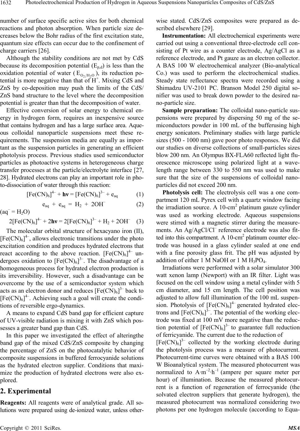 Photoelectrochemical Production of Hydrogen in Aqueous Suspensions Nanoparticles Composites of CdS/ZnS 1632 number of surface specific active sites for both chemical reactions and photon absorption. When particle size de- creases below the Bohr radius of the first excitation state, quantum size effects can occur due to the confinement of charge carriers [26]. Although the stability conditions are not met by CdS because its decomposition potential (Ep,d) is less than the oxidation potential of water (22 OHO ), its reduction po- tential is more negative than that of H+. Mixing CdS and ZnS by co-deposition may push the limits of the CdS/ ZnS band structure to the level where the decomposition potential is greater than that the decomposition of water. E Effective conversion of solar energy to chemical en- ergy in hydrogen form, requires an inexpensive source that contains hydrogen and has a large surface area. Aque- ous colloidal nanoparticle suspensions meet these re- quirements. The suspension media are equally as impor- tant as the suspension particles in generating an efficient photolysis process. Previous studies used semiconductor particles as photoactive systems in heterogeneous charge transfer processes at the particle/electrolyte interface [27, 28]. Hydrated electrons can play an important role in pho- to-dissociation of water through this reaction: [Fe(CN)6]4– + hν = [Fe(CN)6]3– + eaq (1) eaq + eaq = H2 + 2OH– (2) (aq– = H2O) 2[Fe(CN)6]4– + 2hν = 2[Fe(CN)6]3– + H2 + 2OH– (3) The molecular orbital structure of hexacyano iron (II), [Fe(CN)6]4–, allows electronic transitions under the photo excitation condition and produces hydrated electrons that react according to the above reaction. [Fe(CN)6]4– un- dergoes oxidation to [Fe(CN)6]3–. The disadvantage of a homogeneous process for hydrated electron production is its irreversibility. However, such a disadvantage can be overcome by the use of a semiconductor system which acts as an electron donor and reduces [Fe(CN)6]3– back to [Fe(CN)6]4–. Achieving such a goal will create the condi- tions of reversible ergo-dynamics. A means to expand CdS band gap for efficient capture of UV-visible radiation is mixing it with ZnS which pos- sesses a greater band gap than CdS. In this paper we investigated the effect of alteringthe band gap of the mixed CdS/ZnS composite by changing the percentage of ZnS on the photocatalytic behavior of composite suspensions in buffered ferrocyanide solutions as the hydrated electron supplier. Conditions that maxi- mize the production of hydrated electrons were also ex- plored. 2. Experimental Reagents: All reagents were of analytical grade. All so- lutions were prepared using de-ionized water, unless other- wise stated. CdS/ZnS composites were prepared as de- scribed elsewhere [29]. Instrumentation: All electrochemical experiments were carried out using a conventional three-electrode cell con- sisting of Pt wire as a counter electrode, Ag/AgCl as a reference electrode, and Pt gauze as an electron collector. A BAS 100 W electrochemical analyzer (Bio-analytical Co.) was used to perform the electrochemical studies. Steady state reflectance spectra were recorded using a Shimadzu UV-2101 PC. Branson Model 250 digital so- nifier was used to break down powder to the desired na- no-particle size. Sample preparation: The colloidal nano-particle sus- pensions were prepared by dispersing 50 mg of the se- miconductors powder in 100 mL of the bufferusing high energy sonicators. Preliminary studies with large particle sizes (500 - 1000 nm) gave poor photo responses. We did our studies on diverse collections of small-particles sizes blow 200 nm. An Olympus BX-FLA60 reflected light flu- orescence microscope using polarized light at a wave- length range between 330 to 550 nm was used to make sure that the size of the suspensions of colloidal nano- particles did not exceed 200 nm. Photolysis cell: The electrolysis cell was a one com- partment 120 mL Pyrex cell with a quartz window facing the irradiation source. A 10-cm2 platinum gauze cylinder was used as working electrode. Aqueous suspensions were stirred with a magnetic stirrer during the measure- ments. An Ag/AgCl/Cl– reference electrode was also fit- ted into this compartment. A 10-cm2 platinum counter elec- trode was housed in a glass cylinder sealed at one end with a fine porosity glass frit. The pH was adjusted by addition of either 1 M NaOH or 1 M H3PO4. Irradiations were performed with a solar simulator 300 watt xenon lamp (Newport) with an IR filter. Light was focused on the cell window using a metal cylinder with 5 cm diameter, and 15 cm length. The cell position was adjusted to allow full illumination of the 100 mL suspen- sion. Photolysis of [Fe(CN)6]4– generated hydrated elec- trons and [Fe(CN)6]3–. The potential of the working elec- trode was fixed at 100 mV more negative than the reduc- tion potential of [Fe(CN)6]3– to guarantee full reduction of ferricyanide. The current due to the reduction of [Fe(CN)6]3– collected by the working electrode during the photolysis process was a measure of photocurrent. Photocurrent-time curves were obtained with a BAS 100 W Bioanalytical system. The measured photocurrent was normalized to A·m–2·h–1 (ampere per square meter per hour) of illumination. Because the measured photocur- rent is a function of regeneration of ferrocyanide (the solvated electron suppliers that generate hydrogen), the measured photocurrent was normalized considering two photons per one hydrogen molecule (according to Equa- Copyright © 2011 SciRes. MSA 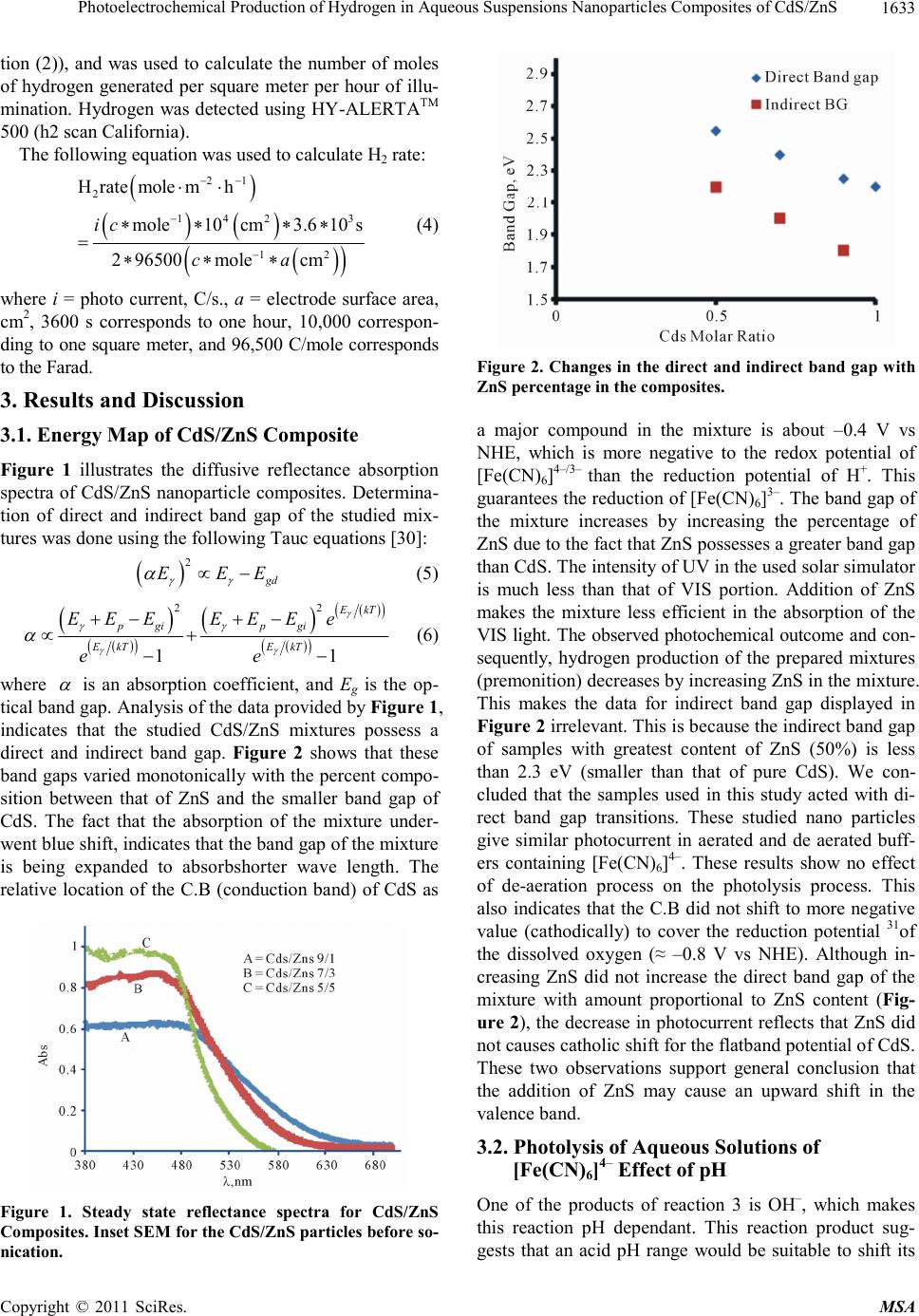 Photoelectrochemical Production of Hydrogen in Aqueous Suspensions Nanoparticles Composites of CdS/ZnS1633 tion (2)), and was used to calculate the number of moles of hydrogen generated per square meter per hour of illu- mination. Hydrogen was detected using HY-ALERTATM 500 (h2 scan California). The following equation was used to calculate H2 rate: 21 2 1423 12 Hratemolemh mole10cm3.610 s 2 96500molecm ic ca (4) where i = photo current, C/s., a = electrode surface area, cm2, 3600 s corresponds to one hour, 10,000 correspon- ding to one square meter, and 96,500 C/mole corresponds to the Farad. 3. Results and Discussion 3.1. Energy Map of CdS/ZnS Composite Figure 1 illustrates the diffusive reflectance absorption spectra of CdS/ZnS nanoparticle composites. Determina- tion of direct and indirect band gap of the studied mix- tures was done using the following Tauc equations [30]: 2 gd E EE (5) 22 1 EkT pgi pgi EkT EkT EEEEEE e ee 1 (6) where is an absorption coefficient, and Eg is the op- tical band gap. Analysis of the data provided by Figure 1, indicates that the studied CdS/ZnS mixtures possess a direct and indirect band gap. Figure 2 shows that these band gaps varied monotonically with the percent compo- sition between that of ZnS and the smaller band gap of CdS. The fact that the absorption of the mixture under- went blue shift, indicates that the band gap of the mixture is being expanded to absorbshorter wave length. The relative location of the C.B (conduction band) of CdS as Figure 1. Steady state reflectance spectra for CdS/ZnS Composites. Inset SEM for the CdS/ZnS particles before so- nication. Figure 2. Changes in the direct and indirect band gap with ZnS percentage in the composites. a major compound in the mixture is about –0.4 V vs NHE, which is more negative to the redox potential of [Fe(CN)6]4–/3– than the reduction potential of H+. This guarantees the reduction of [Fe(CN)6]3–. The band gap of the mixture increases by increasing the percentage of ZnS due to the fact that ZnS possesses a greater band gap than CdS. The intensity of UV in the used solar simulator is much less than that of VIS portion. Addition of ZnS makes the mixture less efficient in the absorption of the VIS light. The observed photochemical outcome and con- sequently, hydrogen production of the prepared mixtures (premonition) decreases by increasing ZnS in the mixture. This makes the data for indirect band gap displayed in Figure 2 irrelevant. This is because the indirect band gap of samples with greatest content of ZnS (50%) is less than 2.3 eV (smaller than that of pure CdS). We con- cluded that the samples used in this study acted with di- rect band gap transitions. These studied nano particles give similar photocurrent in aerated and de aerated buff- ers containing [Fe(CN)6]4–. These results show no effect of de-aeration process on the photolysis process. This also indicates that the C.B did not shift to more negative value (cathodically) to cover the reduction potential 31of the dissolved oxygen (≈ –0.8 V vs NHE). Although in- creasing ZnS did not increase the direct band gap of the mixture with amount proportional to ZnS content (Fig- ure 2), the decrease in photocurrent reflects that ZnS did not causes catholic shift for the flatband potential of CdS. These two observations support general conclusion that the addition of ZnS may cause an upward shift in the valence band. 3.2. Photolysis of Aqueous Solutions of [Fe( CN)6]4– Effect of pH One of the products of reaction 3 is OH–, which makes this reaction pH dependant. This reaction product sug- gests that an acid pH range would be suitable to shift its Copyright © 2011 SciRes. MSA 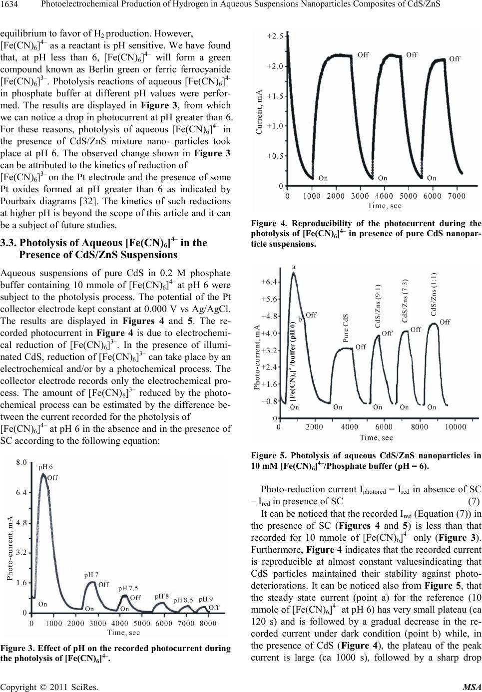 Photoelectrochemical Production of Hydrogen in Aqueous Suspensions Nanoparticles Composites of CdS/ZnS 1634 equilibrium to favor of H2 production. However, [Fe(CN)6]4– as a reactant is pH sensitive. We have found that, at pH less than 6, [Fe(CN)6]4– will form a green compound known as Berlin green or ferric ferrocyanide [Fe(CN)6]3–. Photolysis reactions of aqueous [Fe(CN)6]4- in phosphate buffer at different pH values were perfor- med. The results are displayed in Figure 3, from which we can notice a drop in photocurrent at pH greater than 6. For these reasons, photolysis of aqueous [Fe(CN)6]4– in the presence of CdS/ZnS mixture nano- particles took place at pH 6. The observed change shown in Figure 3 can be attributed to the kinetics of reduction of [Fe(CN)6]3– on the Pt electrode and the presence of some Pt oxides formed at pH greater than 6 as indicated by Pourbaix diagrams [32]. The kinetics of such reductions at higher pH is beyond the scope of this article and it can be a subject of future studies. 3.3. Photolysis of Aqueous [Fe(CN)6]4– in the Presence of CdS/ZnS Suspensions Aqueous suspensions of pure CdS in 0.2 M phosphate buffer containing 10 mmole of [Fe(CN)6]4– at pH 6 were subject to the photolysis process. The potential of the Pt collector electrode kept constant at 0.000 V vs Ag/AgCl. The results are displayed in Figures 4 and 5. The re- corded photocurrent in Figure 4 is due to electrochemi- cal reduction of [Fe(CN)6]3–. In the presence of illumi- nated CdS, reduction of [Fe(CN)6]3– can take place by an electrochemical and/or by a photochemical process. The collector electrode records only the electrochemical pro- cess. The amount of [Fe(CN)6]3– reduced by the photo- chemical process can be estimated by the difference be- tween the current recorded for the photolysis of [Fe(CN)6]4– at pH 6 in the absence and in the presence of SC according to the following equation: Figure 3. Effect of pH on the recorded photocurrent during the photolysis of [Fe(CN)6]4–. Figure 4. Reproducibility of the photocurrent during the photolysis of [Fe(CN)6]4– in presence of pure CdS nanopar- ticle suspensions. Figure 5. Photolysis of aqueous CdS/ZnS nanoparticles in 10 mM [Fe(CN)6]4–/Phosphate buffer (pH = 6). Photo-reduction current Iphotored = Ired in absence of SC – Ired in presence of SC (7) It can be noticed that the recorded Ired (Equation (7)) in the presence of SC (Figures 4 and 5) is less than that recorded for 10 mmole of [Fe(CN)6]4– only (Figure 3). Furthermore, Figure 4 indicates that the recorded current is reproducible at almost constant valuesindicating that CdS particles maintained their stability against photo- deteriorations. It can be noticed also from Figure 5, that the steady state current (point a) for the reference (10 mmole of [Fe(CN)6]4– at pH 6) has very small plateau (ca 120 s) and is followed by a gradual decrease in the re- corded current under dark condition (point b) while, in the presence of CdS (Figure 4), the plateau of the peak current is large (ca 1000 s), followed by a sharp drop Copyright © 2011 SciRes. MSA 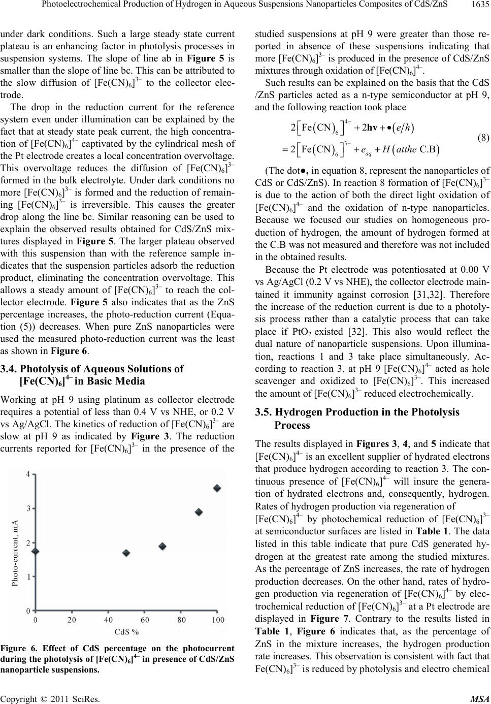 Photoelectrochemical Production of Hydrogen in Aqueous Suspensions Nanoparticles Composites of CdS/ZnS1635 under dark conditions. Such a large steady state current plateau is an enhancing factor in photolysis processes in suspension systems. The slope of line ab in Figure 5 is smaller than the slope of line bc. This can be attributed to the slow diffusion of [Fe(CN)6]3– to the collector elec- trode. The drop in the reduction current for the reference system even under illumination can be explained by the fact that at steady state peak current, the high concentra- tion of [Fe(CN)6]4– captivated by the cylindrical mesh of the Pt electrode creates a local concentration overvoltage. This overvoltage reduces the diffusion of [Fe(CN)6]3– formed in the bulk electrolyte. Under dark conditions no more [Fe(CN)6]3– is formed and the reduction of remain- ing [Fe(CN)6]3– is irreversible. This causes the greater drop along the line bc. Similar reasoning can be used to explain the observed results obtained for CdS/ZnS mix- tures displayed in Figure 5. The larger plateau observed with this suspension than with the reference sample in- dicates that the suspension particles adsorb the reduction product, eliminating the concentration overvoltage. This allows a steady amount of [Fe(CN)6]3– to reach the col- lector electrode. Figure 5 also indicates that as the ZnS percentage increases, the photo-reduction current (Equa- tion (5)) decreases. When pure ZnS nanoparticles were used the measured photo-reduction current was the least as shown in Figure 6. 3.4. Photolysis of Aqueous Solutions of [Fe( CN)6]4– in Basic Media Working at pH 9 using platinum as collector electrode requires a potential of less than 0.4 V vs NHE, or 0.2 V vs Ag/AgCl. The kinetics of reduction of [Fe(CN)6]3– are slow at pH 9 as indicated by Figure 3. The reduction currents reported for [Fe(CN)6]3– in the presence of the Figure 6. Effect of CdS percentage on the photocurrent during the photolysis of [Fe(CN)6]4– in presence of CdS/ZnS nanoparticle suspensions. studied suspensions at pH 9 were greater than those re- ported in absence of these suspensions indicating that more [Fe(CN)6]3– is produced in the presence of CdS/ZnS mixtures through oxidation of [Fe(CN)6]4–. Such results can be explained on the basis that the CdS /ZnS particles acted as a n-type semiconductor at pH 9, and the following reaction took place 4 6 3 6 2FeCN2 2FeCN C.B aq eh eHatthe hv (8) (The dot●, in equation 8, represent the nanoparticles of CdS or CdS/ZnS). In reaction 8 formation of [Fe(CN)6]3– is due to the action of both the direct light oxidation of [Fe(CN)6]4– and the oxidation of n-type nanoparticles. Because we focused our studies on homogeneous pro- duction of hydrogen, the amount of hydrogen formed at the C.B was not measured and therefore was not included in the obtained results. Because the Pt electrode was potentiosated at 0.00 V vs Ag/AgCl (0.2 V vs NHE), the collector electrode main- tained it immunity against corrosion [31,32]. Therefore the increase of the reduction current is due to a photoly- sis process rather than a catalytic process that can take place if PtO2 existed [32]. This also would reflect the dual nature of nanoparticle suspensions. Upon illumina- tion, reactions 1 and 3 take place simultaneously. Ac- cording to reaction 3, at pH 9 [Fe(CN)6]4– acted as hole scavenger and oxidized to [Fe(CN)6]3–. This increased the amount of [Fe(CN)6]3– reduced electrochemically. 3.5. Hydrogen Production in the Photolysis Process The results displayed in Figures 3, 4, and 5 indicate that [Fe(CN)6]4– is an excellent supplier of hydrated electrons that produce hydrogen according to reaction 3. The con- tinuous presence of [Fe(CN)6]4– will insure the genera- tion of hydrated electrons and, consequently, hydrogen. Rates of hydrogen production via regeneration of [Fe(CN)6]4– by photochemical reduction of [Fe(CN)6]3– at semiconductor surfaces are listed in Table 1. The data listed in this table indicate that pure CdS generated hy- drogen at the greatest rate among the studied mixtures. As the percentage of ZnS increases, the rate of hydrogen production decreases. On the other hand, rates of hydro- gen production via regeneration of [Fe(CN)6]4– by elec- trochemical reduction of [Fe(CN)6]3– at a Pt electrode are displayed in Figure 7. Contrary to the results listed in Table 1, Figure 6 indicates that, as the percentage of ZnS in the mixture increases, the hydrogen production rate increases. This observation is consistent with fact that Fe(CN) 6]3– is reduced by photolysis and electro chemical Copyright © 2011 SciRes. MSA 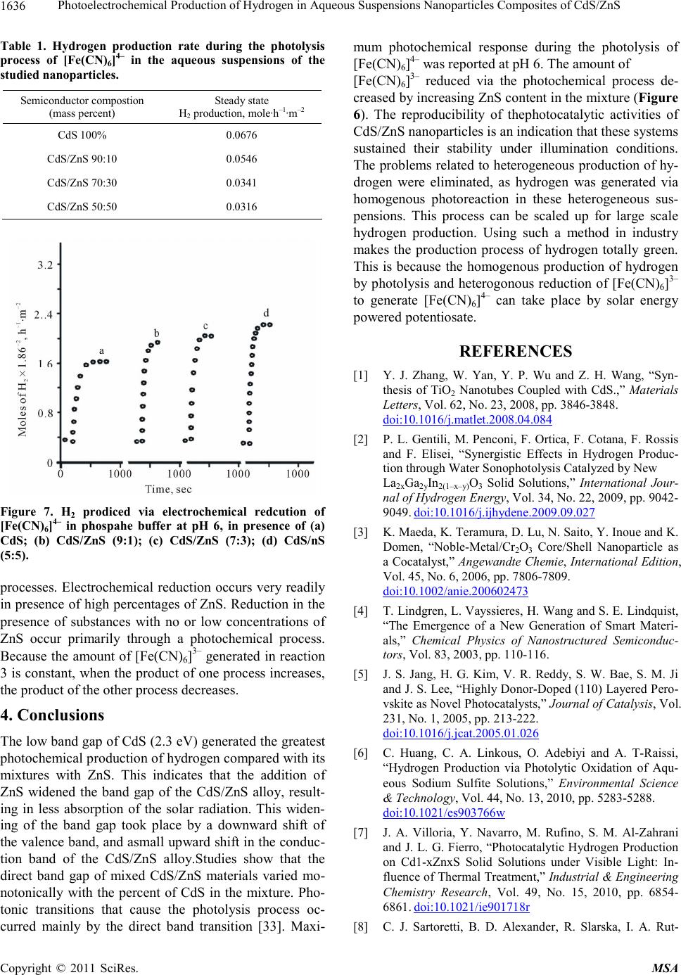 Photoelectrochemical Production of Hydrogen in Aqueous Suspensions Nanoparticles Composites of CdS/ZnS 1636 Table 1. Hydrogen production rate during the photolysis process of [Fe(CN)6]4– in the aqueous suspensions of the studied nanoparticles. Semiconductor compostion (mass percent) Steady state H2 production, mole·h–1·m–2 CdS 100% 0.0676 CdS/ZnS 90:10 0.0546 CdS/ZnS 70:30 0.0341 CdS/ZnS 50:50 0.0316 Figure 7. H2 prodiced via electrochemical redcution of [Fe(CN)6]4– in phospahe buffer at pH 6, in presence of (a) CdS; (b) CdS/ZnS (9:1); (c) CdS/ZnS (7:3); (d) CdS/nS (5:5). processes. Electrochemical reduction occurs very readily in presence of high percentages of ZnS. Reduction in the presence of substances with no or low concentrations of ZnS occur primarily through a photochemical process. Because the amount of [Fe(CN)6]3– generated in reaction 3 is constant, when the product of one process increases, the product of the other process decreases. 4. Conclusions The low band gap of CdS (2.3 eV) generated the greatest photochemical production of hydrogen compared with its mixtures with ZnS. This indicates that the addition of ZnS widened the band gap of the CdS/ZnS alloy, result- ing in less absorption of the solar radiation. This widen- ing of the band gap took place by a downward shift of the valence band, and asmall upward shift in the conduc- tion band of the CdS/ZnS alloy.Studies show that the direct band gap of mixed CdS/ZnS materials varied mo- notonically with the percent of CdS in the mixture. Pho- tonic transitions that cause the photolysis process oc- curred mainly by the direct band transition [33]. Maxi- mum photochemical response during the photolysis of [Fe(CN)6]4– was reported at pH 6. The amount of [Fe(CN)6]3– reduced via the photochemical process de- creased by increasing ZnS content in the mixture (Figure 6). The reproducibility of thephotocatalytic activities of CdS/ZnS nanoparticles is an indication that these systems sustained their stability under illumination conditions. The problems related to heterogeneous production of hy- drogen were eliminated, as hydrogen was generated via homogenous photoreaction in these heterogeneous sus- pensions. This process can be scaled up for large scale hydrogen production. Using such a method in industry makes the production process of hydrogen totally green. This is because the homogenous production of hydrogen by photolysis and heterogonous reduction of [Fe(CN)6]3– to generate [Fe(CN)6]4– can take place by solar energy powered potentiosate. REFERENCES [1] Y. J. Zhang, W. Yan, Y. P. Wu and Z. H. Wang, “Syn- thesis of TiO2 Nanotubes Coupled with CdS.,” Materials Letters, Vol. 62, No. 23, 2008, pp. 3846-3848. doi:10.1016/j.matlet.2008.04.084 [2] P. L. Gentili, M. Penconi, F. Ortica, F. Cotana, F. Rossis and F. Elisei, “Synergistic Effects in Hydrogen Produc- tion through Water Sonophotolysis Catalyzed by New La2xGa2yIn2(1–x–y)O3 Solid Solutions,” International Jour- nal of Hydrogen Energy, Vol. 34, No. 22, 2009, pp. 9042- 9049. doi:10.1016/j.ijhydene.2009.09.027 [3] K. Maeda, K. Teramura, D. Lu, N. Saito, Y. Inoue and K. Domen, “Noble-Metal/Cr2O3 Core/Shell Nanoparticle as a Cocatalyst,” Angewandte Chemie, International Edition, Vol. 45, No. 6, 2006, pp. 7806-7809. doi:10.1002/anie.200602473 [4] T. Lindgren, L. Vayssieres, H. Wang and S. E. Lindquist, “The Emergence of a New Generation of Smart Materi- als,” Chemical Physics of Nanostructured Semiconduc- tors, Vol. 83, 2003, pp. 110-116. [5] J. S. Jang, H. G. Kim, V. R. Reddy, S. W. Bae, S. M. Ji and J. S. Lee, “Highly Donor-Doped (110) Layered Pero- vskite as Novel Photocatalysts,” Journal of Catalysis, Vol. 231, No. 1, 2005, pp. 213-222. doi:10.1016/j.jcat.2005.01.026 [6] C. Huang, C. A. Linkous, O. Adebiyi and A. T-Raissi, “Hydrogen Production via Photolytic Oxidation of Aqu- eous Sodium Sulfite Solutions,” Environmental Science & Technology, Vol. 44, No. 13, 2010, pp. 5283-5288. doi:10.1021/es903766w [7] J. A. Villoria, Y. Navarro, M. Rufino, S. M. Al-Zahrani and J. L. G. Fierro, “Photocatalytic Hydrogen Production on Cd1-xZnxS Solid Solutions under Visible Light: In- fluence of Thermal Treatment,” Industrial & Engineering Chemistry Research, Vol. 49, No. 15, 2010, pp. 6854- 6861. doi:10.1021/ie901718r [8] C. J. Sartoretti, B. D. Alexander, R. Slarska, I. A. Rut- Copyright © 2011 SciRes. MSA 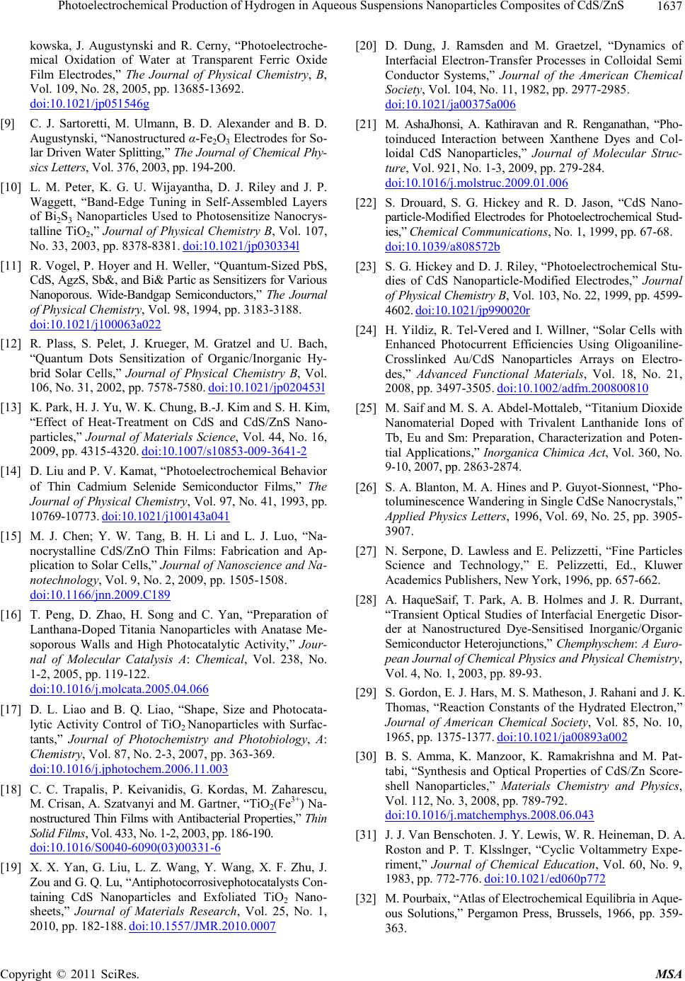 Photoelectrochemical Production of Hydrogen in Aqueous Suspensions Nanoparticles Composites of CdS/ZnS1637 kowska, J. Augustynski and R. Cerny, “Photoelectroche- mical Oxidation of Water at Transparent Ferric Oxide Film Electrodes,” The Journal of Physical Chemistry, B, Vol. 109, No. 28, 2005, pp. 13685-13692. doi:10.1021/jp051546g [9] C. J. Sartoretti, M. Ulmann, B. D. Alexander and B. D. Augustynski, “Nanostructured α-Fe2O3 Electrodes for So- lar Driven Water Splitting,” The Journal of Chemical Phy- sics Letters, Vol. 376, 2003, pp. 194-200. [10] L. M. Peter, K. G. U. Wijayantha, D. J. Riley and J. P. Waggett, “Band-Edge Tuning in Self-Assembled Layers of Bi2S3 Nanoparticles Used to Photosensitize Nanocrys- talline TiO2,” Journal of Physical Chemistry B, Vol. 107, No. 33, 2003, pp. 8378-8381. doi:10.1021/jp030334l [11] R. Vogel, P. Hoyer and H. Weller, “Quantum-Sized PbS, CdS, AgzS, Sb&, and Bi& Partic as Sensitizers for Various Nanoporous. Wide-Bandgap Semiconductors,” The Journal of Physical Chemistry, Vol. 98, 1994, pp. 3183-3188. doi:10.1021/j100063a022 [12] R. Plass, S. Pelet, J. Krueger, M. Gratzel and U. Bach, “Quantum Dots Sensitization of Organic/Inorganic Hy- brid Solar Cells,” Journal of Physical Chemistry B, Vol. 106, No. 31, 2002, pp. 7578-7580. doi:10.1021/jp020453l [13] K. Park, H. J. Yu, W. K. Chung, B.-J. Kim and S. H. Kim, “Effect of Heat-Treatment on CdS and CdS/ZnS Nano- particles,” Journal of Materials Science, Vol. 44, No. 16, 2009, pp. 4315-4320. doi:10.1007/s10853-009-3641-2 [14] D. Liu and P. V. Kamat, “Photoelectrochemical Behavior of Thin Cadmium Selenide Semiconductor Films,” The Journal of Physical Chemistry, Vol. 97, No. 41, 1993, pp. 10769-10773. doi:10.1021/j100143a041 [15] M. J. Chen; Y. W. Tang, B. H. Li and L. J. Luo, “Na- nocrystalline CdS/ZnO Thin Films: Fabrication and Ap- plication to Solar Cells,” Journal of Nanoscience and Na- notechnology, Vol. 9, No. 2, 2009, pp. 1505-1508. doi:10.1166/jnn.2009.C189 [16] T. Peng, D. Zhao, H. Song and C. Yan, “Preparation of Lanthana-Doped Titania Nanoparticles with Anatase Me- soporous Walls and High Photocatalytic Activity,” Jour- nal of Molecular Catalysis A: Chemical, Vol. 238, No. 1-2, 2005, pp. 119-122. doi:10.1016/j.molcata.2005.04.066 [17] D. L. Liao and B. Q. Liao, “Shape, Size and Photocata- lytic Activity Control of TiO2 Nanoparticles with Surfac- tants,” Journal of Photochemistry and Photobiology, A: Chemistry, Vol. 87, No. 2-3, 2007, pp. 363-369. doi:10.1016/j.jphotochem.2006.11.003 [18] C. C. Trapalis, P. Keivanidis, G. Kordas, M. Zaharescu, M. Crisan, A. Szatvanyi and M. Gartner, “TiO2(Fe3+) Na- nostructured Thin Films with Antibacterial Properties,” Thin Solid Films, Vol. 433, No. 1-2, 2003, pp. 186-190. doi:10.1016/S0040-6090(03)00331-6 [19] X. X. Yan, G. Liu, L. Z. Wang, Y. Wang, X. F. Zhu, J. Zou and G. Q. Lu, “Antiphotocorrosivephotocatalysts Con- taining CdS Nanoparticles and Exfoliated TiO2 Nano- sheets,” Journal of Materials Research, Vol. 25, No. 1, 2010, pp. 182-188. doi:10.1557/JMR.2010.0007 [20] D. Dung, J. Ramsden and M. Graetzel, “Dynamics of Interfacial Electron-Transfer Processes in Colloidal Semi Conductor Systems,” Journal of the American Chemical Society, Vol. 104, No. 11, 1982, pp. 2977-2985. do i:10. 1021/ja00375a006 [21] M. AshaJhonsi, A. Kathiravan and R. Renganathan, “Pho- toinduced Interaction between Xanthene Dyes and Col- loidal CdS Nanoparticles,” Journal of Molecular Struc- ture, Vol. 921, No. 1-3, 2009, pp. 279-284. doi:10.1016/j.molstruc.2009.01.006 [22] S. Drouard, S. G. Hickey and R. D. Jason, “CdS Nano- particle-Modified Electrodes for Photoelectrochemical Stud- ies,” Chemical Communications, No. 1, 1999, pp. 67-68. doi:10.1039/a808572b [23] S. G. Hickey and D. J. Riley, “Photoelectrochemical Stu- dies of CdS Nanoparticle-Modified Electrodes,” Journal of Physical Chemistry B, Vol. 103, No. 22, 1999, pp. 4599- 4602. doi:10.1021/jp990020r [24] H. Yildiz, R. Tel-Vered and I. Willner, “Solar Cells with Enhanced Photocurrent Efficiencies Using Oligoaniline- Crosslinked Au/CdS Nanoparticles Arrays on Electro- des,” Advanced Functional Materials, Vol. 18, No. 21, 2008, pp. 3497-3505. doi:10.1002/adfm.200800810 [25] M. Saif and M. S. A. Abdel-Mottaleb, “Titanium Dioxide Nanomaterial Doped with Trivalent Lanthanide Ions of Tb, Eu and Sm: Preparation, Characterization and Poten- tial Applications,” Inorganica Chimica Act, Vol. 360, No. 9-10, 2007, pp. 2863-2874. [26] S. A. Blanton, M. A. Hines and P. Guyot-Sionnest, “Pho- toluminescence Wandering in Single CdSe Nanocrystals,” Applied Physics Letters, 1996, Vol. 69, No. 25, pp. 3905- 3907. [27] N. Serpone, D. Lawless and E. Pelizzetti, “Fine Particles Science and Technology,” E. Pelizzetti, Ed., Kluwer Academics Publishers, New York, 1996, pp. 657-662. [28] A. HaqueSaif, T. Park, A. B. Holmes and J. R. Durrant, “Transient Optical Studies of Interfacial Energetic Disor- der at Nanostructured Dye-Sensitised Inorganic/Organic Semiconductor Heterojunctions,” Chemphyschem: A Euro- pean Journal of Chemical Physics and Physical Chemistry, Vol. 4, No. 1, 2003, pp. 89-93. [29] S. Gordon, E. J. Hars, M. S. Matheson, J. Rahani and J. K. Thomas, “Reaction Constants of the Hydrated Electron,” Journal of American Chemical Society, Vol. 85, No. 10, 1965, pp. 1375-1377. doi:10.1021/ja00893a002 [30] B. S. Amma, K. Manzoor, K. Ramakrishna and M. Pat- tabi, “Synthesis and Optical Properties of CdS/Zn Score- shell Nanoparticles,” Materials Chemistry and Physics, Vol. 112, No. 3, 2008, pp. 789-792. doi:10.1016/j.matchemphys.2008.06.043 [31] J. J. Van Benschoten. J. Y. Lewis, W. R. Heineman, D. A. Roston and P. T. Klsslnger, “Cyclic Voltammetry Expe- riment,” Journal of Chemical Education, Vol. 60, No. 9, 1983, pp. 772-776. doi:10.1021/ed060p772 [32] M. Pourbaix, “Atlas of Electrochemical Equilibria in Aque- ous Solutions,” Pergamon Press, Brussels, 1966, pp. 359- 363. Copyright © 2011 SciRes. MSA  Photoelectrochemical Production of Hydrogen in Aqueous Suspensions Nanoparticles Composites of CdS/ZnS Copyright © 2011 SciRes. MSA 1638 [33] L. G. Arriaga and A. M. Fernoandez, “Determination of Flat Band Potential and Photocurrent Response in (Cd,Zn)S Used in Photoelectrolysis Process,” International Journal of Hydrogen Energy, Vol. 27, No. 1, 2002, pp. 27-31. doi:10.1016/S0360-3199(01)00084-2 |