

Paper Menu >>
Journal Menu >>
 Vol.2, No.6, 431-434 (2009) doi:10.4236/jbise.2009.26062 SciRes Copyright © 2009 Openly accessible at http://www.scirp.org/journal/JBISE/ JBiSE Design of occlusion pressure testing system for infusion pump Peng Zhang1, Shu-Yi Wang1, Chuan-Yi Yu1, Min-Yan Zhang1 1School of Medical Instrument and Food Engineering, University of Shanghai for Science and Technology, Shanghai, China. Email: [email protected] Received 23 June 2008; revised 16 July 2009; accepted 28 July 2009. ABSTRACT Reliability of medical devices such as infusion pumps is extremely important because these devices are being used in patients who are in critical condition. Occlusion pressure, as an important parameter of infusion pumps, should be detected when an occlusion occurred. How- ever, infusion pumps’ occlusion pressure could not be tested and the performance of these pumps is not known to us. In order to test the occlusion pressure of infusion pump, a testing system has been put forward according to standards of IEC 60601-2-24:1998/ GB 9706.27- 2005. The system is comprised of sensor, ac- quisition card, three-way tap and so on; this system is controlled by a PC. At the same time, sampling rate could be changed if necessary and test time could be recorded. And then the characteristics of this system were studied, such as linear, effects of pump rates and dif- ferent pumps. The system remained linear in a given environment. The higher is the pump rate, the faster is the time to reach occlusion condi- tion. The testing system has been proved to be effective in testing the occlusion pressure of infusion pumps and the accuracy error of pressure is content the demand of ±1% of range. Keywords: Infusion Pump; Occlusion Pressure; Testing System 1. INTRODUCTION Infusion pumps have been widely used in clinical prac- tice, such as in intravenous infusion therapy to infuse fluids, medication or nutrients into patient’s circulatory system and can produce quite high but controlled pres- sure so as to inject controlled amount of fluids, however, pressure values are different regarding to different pumps. Nowadays, most infusion pumps have an occlusion pressure preset threshold, once the pressure of tubing, connecting to patients, exceeds the preset limit, the alarm of occurring occlusion will be active. Some infu- sion pumps adopt a method of speed administration, in this case, if fluid rate is zero during a certain time and the alarm of occlusion will be active. However, on the one hand, the pressure values of vascular are different regarding to different persons and the same person at different time. When an occlusion occurs along the de- livery path, medication will not be delivered to patient but the pressure does not reach the preset pressure and the alarm will not be active. In this case, the pump can not only continue to operate normally, but it can display erroneous values about the infusion rate and accumu- lated volume. This incorrect record for the patient could lead to an improper analysis, which will cause injury to patient. The higher is occlusion pressure, the more seri- ous is the injury, so the test of occlusion pressu re is cru- cial to pumps [1]. On the other hand, the inaccurate in- fusion rates of infusion pumps could be generated if the pumps are not checked up after a long time usage. At last, some infusion pumps could be used to detect tissue ex- tra vag at io n [ 2]. A t th is mo me nt , infu s ion pu mps mus t b e periodically tested to determine whether they are func- tioning pr o perly [3,4]. A testing system of infusion pump occlusion pressure is designed to test an infusion pump and determine whether the pump is operating correctly. At present, there are several products commercial availably in market; mostly they are designed by for- eigners, such as IDA-4 Plus Infusion Pump Analyzer, Infutest Solo Infusion Pump Analyzer and so on. The former is designed by Fluke, it has a function of PCA (Patient Controlled Analgesia) Pumps Bolus measure- ment and testing four pumps at the same time; the latter is designed by Datrend Systems Inc. and there are other corporations to design infusion pump analyzers (tester) [5,6]. Though these devices have well performances, th e price is high accordingly. At the same time, some of these devices are not designed rationally; one device is 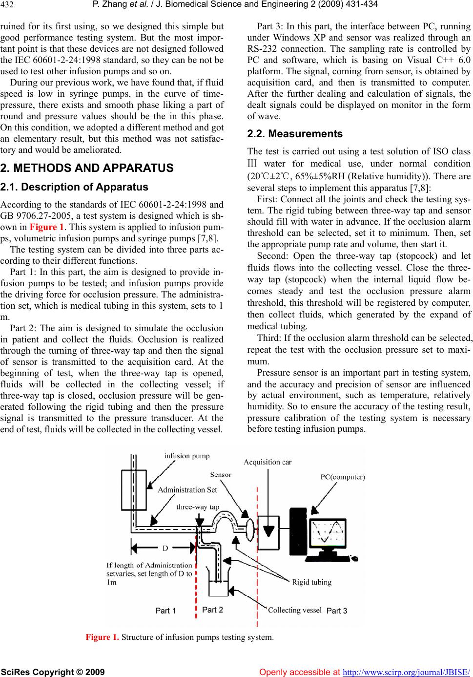 P. Zhang et al. / J. Biomedical Science and Engineering 2 (2009) 431-434 SciRes Copyright © 2009 Openly accessible at http://www.scirp.org/journal/JBISE/ 432 ruined for its first using, so we designed this simple but good performance testing system. But the most impor- tant point is that these devices are not designed followed the IEC 60601-2-24:199 8 stan dard, so th ey can be not be used to test other infusion pumps and so on. During our previous work, we have found that, if fluid speed is low in syringe pumps, in the curve of time- pressure, there exists and smooth phase liking a part of round and pressure values should be the in this phase. On this condition, we adopted a different method and got an elementary result, but this method was not satisfac- tory and would be ameliorated. 2. METHODS AND APPARATUS 2.1. Description of Apparatus According to th e standards of IEC 60601-2-24:1998 and GB 9706.27-2005 , a test system is designed which is sh- own in Fi gure 1. This system is applied to infusion pum- ps, volumetric infusion pumps and syringe pumps [7,8]. The testing system can be divided into three parts ac- cording to their different functions. Part 1: In this part, the aim is designed to provide in- fusion pumps to be tested; and infusion pumps provide the driving force for occlusion pressure. The administra- tion set, which is medical tubing in this system, sets to 1 m. Part 2: The aim is designed to simulate the occlusion in patient and collect the fluids. Occlusion is realized through the turning of three-way tap and then the signal of sensor is transmitted to the acquisition card. At the beginning of test, when the three-way tap is opened, fluids will be collected in the collecting vessel; if three-way tap is closed, occlusion pressure will be gen- erated following the rigid tubing and then the pressure signal is transmitted to the pressure transducer. At the end of test, fluids will be collected in the collecting vessel. Part 3: In this part, the interface between PC, running under Windows XP and sensor was realized through an RS-232 connection. The sampling rate is controlled by PC and software, which is basing on Visual C++ 6.0 platform. The signal, coming from sensor, is obtained by acquisition card, and then is transmitted to computer. After the further dealing and calculation of signals, the dealt signals could be displayed on monitor in the form of wave. 2.2. Measurements The test is carried out using a test solution of ISO class Ⅲ water for medical use, under normal condition (20℃±2℃, 65%±5%RH (Relative humidity)). There are several steps to implement this apparatus [7,8]: First: Connect all the joints and check the testing sys- tem. The rigid tubing between three-way tap and sensor should fill with water in advance. If the occlusion alarm threshold can be selected, set it to minimum. Then, set the appropriate pump rate and volume, then start it. Second: Open the three-way tap (stopcock) and let fluids flows into the collecting vessel. Close the three- way tap (stopcock) when the internal liquid flow be- comes steady and test the occlusion pressure alarm threshold, this threshold will be registered by computer, then collect fluids, which generated by the expand of medical tubing. Third: If the occlusion alarm threshold can be selected, repeat the test with the occlusion pressure set to maxi- mum. Pressure sensor is an important part in testing system, and the accuracy and precision of sensor are influenced by actual environment, such as temperature, relatively humidity. So to ensure the accuracy of the testing result, pressure calibration of the testing system is necessary before testing infu sion pumps. Figure 1. Structure of infusion pumps testing system. 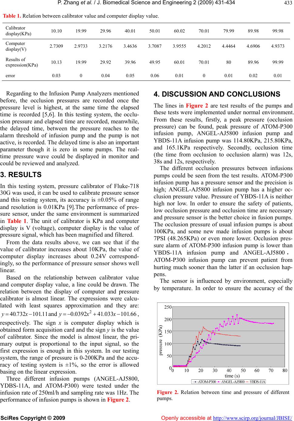 P. Zhang et al. / J. Biomedical Science and Engineering 2 (2009) 431-434 SciRes Copyright © 2009 Openly accessible at http://www.scirp.org/journal/JBISE/ 433 Table 1. Relation between calibrator value and computer display value. Calibrator display(KPa) 10.10 19.99 29.96 40.01 50.01 60.02 70.01 79.99 89.98 99.98 Computer display(V) 2.7309 2.9733 3.2176 3.4636 3.7087 3.9555 4.2012 4.4464 4.6906 4.9373 Results of expression(KPa) 10.13 19.99 29.92 39.96 49.95 60.01 70.01 80 89.96 99.99 error 0.03 0 0.04 0.05 0.06 0.01 0 0.01 0.02 0.01 Regarding to the Infusion Pump Analyzers mentioned before, the occlusion pressures are recorded once the pressure level is highest, at the same time the elapsed time is recorded [5,6]. In this testing system, the occlu- sion pressure and elapsed time are recorded, meanwhile, the delayed time, between the pressure reaches to the alarm threshold of infusion pump and the pump is not active, is recorded. The delayed time is also an important parameter though it is zero in some pumps. The real- time pressure wave could be displayed in monitor and could be reviewed and analyzed. 3. RESULTS In this testing system, pressure calibrator of Fluke-718 30G was used, it can be used to calibrate pressure sensor and this testing system, its accuracy is ±0.05% of range and resolution is 0.01KPa [9].The performance of pres- sure sensor, under the same environment is summarized in Ta b le 1. The unit of calibrator is KPa and computer display is V (voltage), computer display is the value of pressure signal, which has been magnified and filtered. From the data results above, we can see that if the value of calibrator increases about 10KPa, the value of computer display increases about 0.24V correspond- ingly, so the perfor mance of pressur e sensor shows well linear. Based on the relationship between calibrator value and computer display value, a line could be drawn. The relation between the display of computer and pressure calibrator is almost linear. The expressions were calcu- lated with least squares approximation and they are: and , respectively. The sign x is computer display which is obtained form acquisition card and th e sign y is the value of calibrator. Since the model is almost linear, the pri- mary output is proportional to the input signal, so the first expression is enough in this system. In our testing system, the range of pressure is 0-200KPa and the accu- racy of testing system is ±1%, so the error is allowed basing on the linear exp ression. 11.101732.40 xy 66.101033.410392.0 2 xxy Three different infusion pumps (ANGEL-AJ5800, YDBS-11A, and ATOM-P300) were tested under the infusion rate of 250ml/h and sa mpling rate was 1Hz. Th e performance of infusion pumps is shown in Figure 2. 4. DISCUSSION AND CONCLUSIONS The lines in Figure 2 are test results of the pumps and these tests were implemented under normal environment. From these results, firstly, a peak pressure (occlusion pressure) can be found, peak pressure of ATOM-P300 infusion pump, ANGEL-AJ5800 infusion pump and YBDS-11A infusion pump was 114.80KPa, 215.80KPa, and 165.1KPa respectively. Secondly, occlusion time (the time from occlusion to occlusion alarm) was 12s, 38s and 12s, respectiv ely. The different occlusion pressures between infusions pumps could be seen from the test results. ATOM-P300 infusion pump has a pressu re sensor and the precision is high; ANGEL-AJ5800 infusion pump has a higher oc- clusion pressure value. Pressure of YBDS-11A is neither high nor low. In order to ensure the safety of patients, low occlusion pressure and occlusion time are necessary and pressure sensor is the better choice in fusion pumps. The occlusion pressure of usual infusion pumps is about 100KPa, and some new made infusion pumps is about 7PSI (48.265KPa) or even more lower. Occlusion pres- sure alarm of ATOM-P300 infusion pump is lower than YBDS-11A infusion pump and ANGEL-AJ5800, ATOM-P300 infusion pump can prevent patient from hurting much sooner than the latter if an occlusion hap- pens. The sensor is influenced by environment, especially by temperature. In order to ensure the accuracy of the Figure 2. Relation between time and pressure of different pumps. 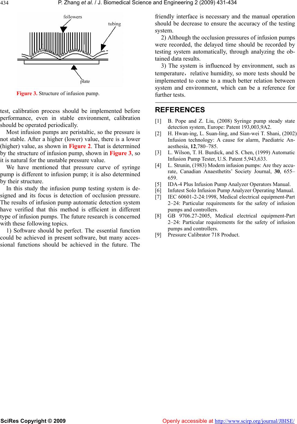 P. Zhang et al. / J. Biomedical Science and Engineering 2 (2009) 431-434 SciRes Copyright © 2009 Openly accessible at http://www.scirp.org/journal/JBISE/ 434 Figure 3. Structure of infusion pump. test, calibration process should be implemented before performance, even in stable environment, calibration should be oper a t ed pe ri o di cal l y. Most infusion pumps are peristaltic, so the pressure is not stable. After a higher (lower) value, there is a lower (higher) value, as shown in Figure 2. That is determined by the structure of infusion pump, shown in Figure 3, so it is natural for the unstable pressure value. We have mentioned that pressure curve of syringe pump is different to infusion pump; it is also determined by their structure. In this study the infusion pump testing system is de- signed and its focus is detection of occlusion pressure. The results of infusion pump automatic detection system have verified that this method is efficient in different type of infusion pumps. The future research is concerned with these following topics. 1) Software should be perfect. The essential function could be achieved in present software, but many acces- sional functions should be achieved in the future. The friendly interface is necessary and the manual operation should be decrease to ensure the accuracy of the testing system. 2) Although the occlusion pressures of infusion pumps were recorded, the delayed time should be recorded by testing system automatically, through analyzing the ob- tained data results. 3) The system is influenced by environment, such as temperature,relative humidity, so more tests should be implemented to come to a much better relation between system and environment, which can be a reference for further tests. REFERENCES [1] B. Pope and Z. Liu, (2008) Syringe pump steady state detection system, Europe: Patent 193,003,9A2. [2] H. Hwan-ing, L. Suan-ling, and Sian-wei T. Shani, (2002) Infusion technology: A cause for alarm, Paediatric An- aesthesia, 12,780–785. [3] L. Wilson, T. H. Burdick, and S. Chen, (1999) Automatic Infusion Pump Tester, U.S. Patent 5,943,633. [4] L. Strunin, (1983) Modern infusion pumps: Are they accu- rate, Canadian Anaesthetits’ Society Journal, 30, 655– 659. [5] IDA-4 Plus Infusion Pump Analyzer Operators Manual. [6] Infutest Solo Infusion Pump Analyzer Operating Manual. [7] IEC 60601-2-24:1998, Medical electrical equipment-Part 2–24: Particular requirements for the safety of infusion pumps and controllers. [8] GB 9706.27-2005, Medical electrical equipment-Part 2–24: Particular requirements for the safety of infusion pumps and controllers. [9] Pressure Calibrator 718 Product. |