

Paper Menu >>
Journal Menu >>
 Journal of Biomaterials and Nanobiotechnology, 2011, 2, 409-413 doi:10.4236/jbnb.2011.24050 Published Online October 2011 (http://www.SciRP.org/journal/jbnb) Copyright © 2011 SciRes. JBNB 409 Controlled Growth of CdS Nanocrystals: Core/Shell viz Matrix Prinsa Verma1,2*, Avinash C Pandey1 1Nanophosphor Application Center, Allahabad University, Allahabad, India; 2Satish Dhawan Space Center, India Space Research Organization, Sriharikota, India. Email: *[email protected] Received March 28th, 2011; revised May 29th, 2011; accepted July 25th, 2011. ABSTRACT The ability to precisely control the size of semiconductor nanocrystals can create an opportunity for producing functional materials with new properties, which are of importance to applications such as Light emitting diodes, b io medical diagnosis, solar cells, and spintronics. And size of nanoparticle can be controlled with efficient capping agent. For the same purpose we reported, two types of capping, one will lead to nanomatrix and other to Shelled nanostructures. Enhancement in emis- sion intensity observed with Shell nanostructures compare to matrix. PVP is used to control the particle size, to preven t ag - glomeration and making thin films. A blue shift in energy level at the nanoscale is demonstrated by optical absorption. Elec- tron microscopy studies with an SEM and TEM show a particle size of 10 nm and 15 nm. We also investigated the particle size distribution of nanoparticles by small angle scattering (SAXS) study. Keywords: Nanomatrix, Shell and Band Edge Emission 1. Introduction Semiconductor quantum dots with diameters less than 10 nm have evoked great interest for intense investiga- tions [1-4]. The number of atoms in such quantum dots ranges from a few tens to hundreds of atoms. These clusters of atoms exhibit the size effect with unique elec- tronic and optical properties that depend upon the size of the cluster. The surface to bulk atom ratio also changes rapidly with size leading to drastic changes in thermal and mechanical properties [5]. A 5 nm CdS cluster has approximately 15% of the atoms on the surfaces. The existence of this vast interface between the cluster and the surrounding medium can have a profound effect on the cluster properties [2]. As the size of CdSe particles decrease from 10 nm to 1 nm, the percentage of surface atoms increases from 20 to practically 100%. The surface atoms usually have unsaturated bonds or dangling bonds. These atoms have extra free energy and are more active than those in the bulk [6]. The size dependent properties appear when the radius of the particle is comparable to the Bohr radius of the exciton in the bulk material. As the particle size decreases the energy gap widens and the absorption edge shifts towards higher energy side ac- companied by the appearance of a strong excitonic peak. By controlling the particle size the forbidden gap in the semiconductor can be tuned and its optical and electronic properties can be tailored so that they can be used in many applications like photocatalysis, flat panel displays, optoelectronic devices, molecular level quantum com- puters, single electron devices etc [7]. For controlling particle size capping is required either with organic or inorganic. A coating shell is built up around the core materials to increase their chemical stability, intensify their functions, improve their biocompatibility compared with bare core materials, and confer specific properties, such as optical, magnetic or mechanical properties on the core materials [8,9]. Organic and inor- ganic material can both used as shell material. Semi- conductor nanocrystals capped with organic molecules can have a relatively large number of unpassivated sur- face sites as it is difficult to passivate both anionic and cationic surface sites simultaneously by these capping groups [10]. These unpassivated surface sites may act as non-radiative recombination centres which suppress their luminescence. In addition, organically capped nanocry- stals have very long emission lifetimes and large Stoke shifts [11] whereas inorganically capped nanoparticles exhibit enhanced luminescence efficiencies [12] and shorter lifetimes [13]. The epitaxial growth of inorganic cap on the nanocrystals can eliminate both the anionic  Controlled Growth of CdS Nanocrystals: Core/Shell viz Matrix 410 and cationic surface dangling bonds [10]. Zou, et al. [11] have studied the effectiveness of various inorganic cap- ping agents having different band gaps on the surface passivation of cadmium sulphide (CdS) nanoparticles. They have reported that it is possible to block the nonra- diative channels on the surface of these nanoparticles by capping them with wider band gap inorganic materials like Cd(OH)2 and zinc sulphide (ZnS). It is also reported that ZnS is more effective than Cd(OH)2 in surface pas- sivation because of its better charge and size compatibil- ity with CdS, resulting in increased band edge emission. Growth of a wide band gap semiconductor ZnS on the surface of a narrower band gap semiconductor CdS, forming CdS/ZnS coreshell nanoparticles, leads to ap- preciable passivation resulting in enhancement of pho- toluminescence (PL) emission [14]. We reported synthesis of Mn2+ doped PVP-CdS nano- matrix and CdS/ZnS core/shell nanostructures through wet chemical approach. We capped CdS with both or- ganic and inorganic capping agents. As organic is re- sponsible for stroke’s shift where as inorganic gives bet- ter enhanced luminescence efficiencies so we can choose capping as per our requirement. After shell formation by ZnS, monodisperse CdS nanoparticles were prepared, which exhibited significantly enhanced luminescence and high chemical stability. PVP role as a capping agent is already discussed in our earlier paper [15]. 2. Experiment Procedures 2.1. Sample Preparation All the reactants and solvents were analytical grade. Cad- mium acetate dihydrate Cd(CH3COO)2·2H2O (98%), manganese acetate Mn(CH3COO)2 (98%), sodium sul- fide (Na2S), zinc acetate Zn(CH3COO)2 (99.99%), were purchased from Aldrich and used to synthesize or passi- vate the CdS:Mn nanocrystals. Each (Cd2+, Zn2+, Mn2+) and S2– containing standard aqueous solution was pre- pared by dissolving Cd(CH3COO)2·2H2O, Zn(CH3COOH)2, Mn(CH3CO O)2, and Na2S in water. The concentrations of Cd2, Zn2+ and S2- in water were 0.1 M and the ratio of Mn2+ to Cd2+ was fixed to 2 mol%. Here we are going to report two synthesis processes. In a typical preparation process 1.5 ml of 0.1M Mn(CH3CO O)2 and 0.05 g PVP was dissolved in 25 ml of 0.1M Cd(CH3COO)2·2H2O aqueous solution followed by 15 ml of 0.1M sodium sulphide with continuous stir- ring until a yellow solution of PVP capped CdS nanoma- trix were formed. Where as in other set 2) 1.5 ml of 0.1M Mn(CH3COO) 2 and 0.05 g PVP was dissolved in 25 ml of 0.1M Cd(CH3COO)2·2H2O aqueous solution, then 15 ml of 0.1M sodium sulphide is added followed by addition of 25 ml of 0.1M Zn(CH3COOH)2 with con- tinuous stirring for favourable synthesis of Core/Shell nanostructurs. Sequential addition of S2− and Zn2+ ions to the (CdS)Mn core solution formed core/shell structures. The obtained yellow solution was stored at roomtempe- rature for measurements of optical absorption and pho- toluminescence properties. Core/shell is a result of reac- tion between Zn(CH3COOH)2 and excess Na2S, which will lead to deposition of ZnS as a shell on the formed core CdS nanoparticle. 2.2. Influence of Organic Capping Two coordinating groups, nitrogen and carboxyl are pre- sent in Poly Vinyl Pyrrolidone (PVP). Oxygen present in PVP molecule makes coordinate bond with the Cd ions whereas the lone pair of electrons on nitrogen in pyr- rolidone is conjugated with the adjacent carbonyl group and remaining oxygen in carboxylate makes coordinate bond with the Mn ions. In PVP-CdS samples, we expect a similar bonding at the nanoparticles, where in C=O-Cd+2 and C=O-Mn2+ bonds which can give rise to overlapping of molecular orbitals of PVP with atomic orbitals of metal ions. PVP as a capping agent plays a significant role not only to increase the stability but also for the effective doping of Mn into the CdS nanophosphors, which can be attributed to the formation of coordinate bonding groups between lone pair of oxygen atoms and those of metallic atoms Cd and Mn in the CdS nanocomposite [15]. 2.3. Characteristics Measurements Transmission electron microscopic (TEM) photographs were taken on Technai 30 G2 S-Twin. Ultraviolet–visi- ble (UV-Vis) measured on Perkin–Elmer Mc Pherson 2035, Small angle scattering pattern were obtained by a Rigaku D/max-2200 PC diffractometer operated at 40 kV/20 mA and Photoluminescence spectrophotometer were measured on a Perkin–Elmer LS 55 spectropho- tometer. 3. Result and Discussion 3.1. TEM Analysis Sample preparation for TEM-Samples in mg were dis- solved in ethanol and sonicated for 2 hrs then one drop of this sample were taken on carbon coated copper grid, and it was dried in oven for 24 hrs at 50˚C. Magnification is 200 KeV. Figures 1(a) and (b) shows a typical TEM images of the CdS/ZnS core/shell nanoparticles and PVP-CdS na- nomatrix. Nanomatrix which are shown in Figure 1(b) was estimated to be 15 nm but they showed non uniform dis- tribution. Where as core/shell CdS/ZnS nanoparticles are well dispersed and estimated to be 10 nm (Figure 1(a)). 3.2. UV-Vis Spectra Pure PVP solution exhibited nearly no absorption in the C opyright © 2011 SciRes. JBNB 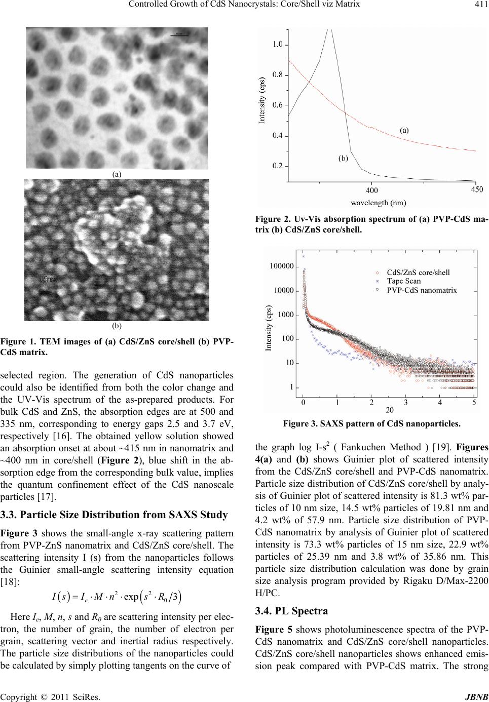 Controlled Growth of CdS Nanocrystals: Core/Shell viz Matrix411 (a) (b) Figure 1. TEM images of (a) CdS/ZnS core/shell (b) PVP- CdS matrix. selected region. The generation of CdS nanoparticles could also be identified from both the color change and the UV-Vis spectrum of the as-prepared products. For bulk CdS and ZnS, the absorption edges are at 500 and 335 nm, corresponding to energy gaps 2.5 and 3.7 eV, respectively [16]. The obtained yellow solution showed an absorption onset at about ~415 nm in nanomatrix and ~400 nm in core/shell (Figure 2), blue shift in the ab- sorption edge from the corresponding bulk value, implies the quantum confinement effect of the CdS nanoscale particles [17]. 3.3. Particle Size Distribution from SAXS Study Figure 3 shows the small-angle x-ray scattering pattern from PVP-ZnS nanomatrix and CdS/ZnS core/shell. The scattering intensity I (s) from the nanoparticles follows the Guinier small-angle scattering intensity equation [18]: 22 0 exp 3 e IsI MnsR Here Ie, M, n, s and R0 are scattering intensity per elec- tron, the number of grain, the number of electron per grain, scattering vector and inertial radius respectively. The particle size distributions of the nanoparticles could be calculated by simply plotting tangents on the curve of Figure 2. Uv-Vis absorption spectrum of (a) PVP-CdS ma- trix (b) CdS/ZnS core/shell. Figure 3. SAXS pattern of CdS nanoparticle s. the graph log I-s2 ( Fankuchen Method ) [19]. Figures 4(a) and (b) shows Guinier plot of scattered intensity from the CdS/ZnS core/shell and PVP-CdS nanomatrix. Particle size distribution of CdS/ZnS core/shell by analy- sis of Guinier plot of scattered intensity is 81.3 wt% par- ticles of 10 nm size, 14.5 wt% particles of 19.81 nm and 4.2 wt% of 57.9 nm. Particle size distribution of PVP- CdS nanomatrix by analysis of Guinier plot of scattered intensity is 73.3 wt% particles of 15 nm size, 22.9 wt% particles of 25.39 nm and 3.8 wt% of 35.86 nm. This particle size distribution calculation was done by grain size analysis program provided by Rigaku D/Max-2200 H/PC. 3.4. PL Spectra Figure 5 shows photoluminescence spectra of the PVP- CdS nanomatrix and CdS/ZnS core/shell nanoparticles. CdS/ZnS core/shell nanoparticles shows enhanced emis- sion peak compared with PVP-CdS matrix. The strong Copyright © 2011 SciRes. JBNB 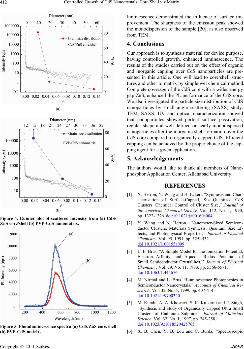 Controlled Growth of CdS Nanocrystals: Core/Shell viz Matrix 412 (a) (b) Figure 4. Guinier plot of scattered intensity from (a) CdS/ ZnS core/shell (b) P VP- CdS nanomatr ix. Figure 5. Photoluminescence spectra (a) CdS/ZnS core/shell (b) PVP-CdS matrix. luminescence demonstrated the influence of surface im- provement. The sharpness of the emission peak showed the monodispersion of the sample [20], as also observed from TEM. 4. Conclusions Our approach is to synthesis material for device purpose, having controlled growth, enhanced luminescence. The results of the studies carried out on the effect of organic and inorganic capping over CdS nanoparticles are pre- sented in this article. One will lead to core/shell struc- tures and other to matrix by simple wet chemical method. Complete coverage of the CdS core with a wider energy gap ZnS, enhanced the PL performance of the CdS core. We also investigated the particle size distribution of CdS nanoparticles by small angle scattering (SAXS) study. TEM, SAXS, UV and optical characterization showed that nanoparticles showed perfect surface passivation, regular shape and well defined or nearly monodispersed nanoparticles after the inorganic shell formation over the CdS core compared to organically capped CdS. Efficient capping can be achieved by the proper choice of the cap- ping agent for a given application. 5. Acknowledgements The authors would like to thank all members of Nano- phosphor Application Center, Allahabad University. REFERENCES [1] N. Herron, Y. Wang and H. Eckert, “Synthesis and Char- acterization of Surface-Capped, Size-Quantized CdS Clusters. Chemical Control of Cluster Size,” Journal of the American Chemical Society, Vol. 112, No. 4, 1990, pp. 1322-1326. doi:10.1021/ja00160a004 [2] Y. Wang and N. Herron, “Nanometer-Sized Semicon- ductor Clusters: Materials Synthesis, Quantum Size Ef- fects, and Photophysical Properties,” Journal of Physical Chemistry, Vol. 95, 1991, pp. 525 -532. doi:10.1021/j100155a009 [3] L. E. Brus, “A Simple Model for the Ionization Potential, Electron Affinity, and Aqueous Redox Potentials of Small Semiconductor Crystallites,’’ Journal of Physical Chemistry, Vol. 79, No. 11, 1983, pp. 5566-5571. doi:10.1063/1.445676 [4] M. Nirmal and L. Brus, “Luminescence Photophysics in Semiconductor Nanocrystals,” Accounts of Chemical Re- search, Vol. 32, No. 5, 1999, pp. 407-414. doi:10.1021/ar9700320 [5] M. Kundu, A. A. Khosravi, S. K. Kulkarni and P. Singh, “Synthesis and Study of Organically Capped Ultra Small Clusters of Cadmium Sulphide,” Journal of Materials Science, Vol. 32, No. 1, 1997, pp. 245-258. doi:10.1023/A:1018520425765 [6] X. B. Chen, Y. B. Lou and C. Burda, “Spectroscopic C opyright © 2011 SciRes. JBNB  Controlled Growth of CdS Nanocrystals: Core/Shell viz Matrix Copyright © 2011 SciRes. JBNB 413 Characterization of II-VI Core-Shell Nanoparticles CdSe/ CdS,” International Journal of Nanotechnology, Vol. 1, No. 1-2, 2004, pp. 105-118. [7] S. K. Kulkarni, U. Winkler, N. Deshmukh, P. H. Borse, R. Fink and E. Umbach, “Investigations on Chemically Capped CdS, ZnS and ZnCdS Nanoparticles,” Applied Surface Science, Vol. 169-170, No. 1-2, 2001, pp. 438-446. doi:10.1016/S0169-4332(00)00700-5 [8] B. Saraswathi-Amma, K. Manzoor, K. Ramakrishna and M. Pattabi, “Synthesis and Optical Properties of CdS/ZnS Coreshell Nnanoparticles,” Materials Chemistry and Physics, Vol. 112, No. 3, 2008, pp. 789-792. doi:10.1016/j.matchemphys.2008.06.043 [9] Y. D. Wuab and L. S. Wang, “A Novel Sonochemical Synthesis and Nanostructured Assembly of Polyvi- nylpyrrolidone-Capped CdS Colloidal Nanoparticles,” Journal of Non-Crystalline Solids, Vol. 354, No. 26, 2008, pp. 2993-3000. doi:10.1016/j.jnoncrysol.2007.12.005 [10] X. G. Peng, M. C. Schlamp, A. V. Kadavanich and A. P. Alivisatos, “Epitaxial Growth of Highly Luminescent CdSe/CdS Core/Shell Nanocrystals with Photostability and Electronic Accessibility,” Journal of the American Chemical Society, Vol. 119, No. 30, 1997, pp. 7019-7029. doi:10.1021/ja970754m [11] B. S. Zou, R. B. Little, J. P. Wang and M. A. El-Sayed, “Effect of Different Capping Environments on the Opti- cal Properties of CdS Nanoparticles in Reverse Micelles,” International Journal of Quantum Chemistry, Vol. 72, No. 4, 1999, pp. 439-450. doi:10.1002/(SICI)1097-461X(1999)72:4<439::AID-QU A27>3.0.CO;2-Q [12] M. A. Hines and P. Guyot-Sionnest, “Synthesis and Char- acterization of Strongly Luminescing ZnS-Capped CdSe Nanocrystals,” Journal of Physical Chemistry, Vol. 100, No. 2, 1996, pp. 468- 471. doi:10.1021/jp9530562 [13] A. Eychmuller, A. Hasselbarth, L. Katsikas and H. Weller, “Fluorescence Mechanism of Highly Monodis- perse Q-Sized CdS Colloids,” Journal of Luminescence, Vol. 48-49, No. 2, 1991, pp. 745-749. doi:10.1016/0022-2313(91)90232-K [14] H. Yang and H. P. Holloway, “Enhanced Photolumines- cence from CdS:Mn/ZnS Core/Shell Quantum Dots,” Ap- plied Physics Letters, Vol. 82, No. 12, 2003, pp. 4633- 4843. doi:10.1063/1.1563305 [15] P. Verma and A. C. Pandey, “Organic Capping-Effect and Mechanism in Mn-Doped CdS Nanocomposites,” Phy- sica B: Condensed Matter, Vol. 405, No. 5, 2010, pp. 1253-1257. doi:10.1016/j.physb.2009.11.060 [16] X. C. Wu, A. M. Bittner and K. Kern, “Synthesis, Photo- luminescence and Adsorption of CdS/Dendrimer Nano- composites,” Journal of Physical Chemistry B, Vol. 109, No. 1, 2005, pp. 230-239. doi:10.1021/jp046072k [17] A. Z. Malik, P. O’Brien and N. Revaprasadu, “Synthesis of TOPO-Capped Mn-doped ZnS and CdS Quantum Dots,” Journal of Material Chemistry, Vol. 11, No. 9, 2001, pp. 2382-2386. doi:10.1039/b102709n [18] A. Guinier and G. Fournet, “Small Angle Scattering of X- rays,” Journal of Polymer Chemistry, Vol. 19, No. 93, 1956, p. 594 . [19] L. E. Alexander, “X-ray Diffraction Methods in Polymer Science,” Journal of Polymer Science Part B: Polymer Letters, Vol. 9, No. 8, 1970, pp. 635-636. [20] S. Sapra, J. Nanda, D. D. Sarma, F. A. El-Al and G. Ho- des, “Blue Emission from Cysteine Ester Passivated Cad- mium Sulfide Nanoclusters,” Chemical Communications, Vol. 21, 2001, pp. 2188-2189. doi:10.1039/b106420g |