

Paper Menu >>
Journal Menu >>
 Int. J. Communications, Network and System Sciences, 2011, 4, 656-661 doi:10.4236/ijcns.2011.410080 Published Online October 2011 (http://www.SciRP.org/journal/ijcns) Copyright © 2011 SciRes. IJCNS Embedded Dual-band Cylindrical Dielectric Resonator Antenna Ahmed Benomar1, Noureddine Boukli Hacene2, Hicham Megnafi3, Patrick Vaudon4 1,2,3Department of Telecommunication, University of Abou Bakr Belkaïd, Tlemcen, Algeria 4XLIM Laboratory, OSA Department , Université de Limoges, Limoges, France E-mail: [email protected], boukl i n @yahoo.com, megnafi.hi ch am @ gm ail .co m, [email protected] Received July 26, 2011; revised August 15, 2011; accepted September 8, 201 1 Abstract A compact dual-band antenna made of high dielectric constant substrate is studied. Embedding a higher di- electric cylindrical inside the substrate host cylindrical enhances the dual-band behaviour. The first part dis- plays the characteristics of single CRDA as return loss, bandwidth and radiation pattern, then, the second part describes the aim of using an antenna, composed by the arrangement of two cylindrical resonators in which the smallest is inserted in the largest, to lead dual-frequency behaviour, and achieve a dual-band an- tenna. The proposed antennas are investigated using Finite Element Method (FEM), the impedance matching dual-band definition and covers the Ultra High Frequency band (UHF). Keywords: Dual-band Antenna, Bandwidth, Return Loss, UHF, DCS 1. Introduction The dielectric resonator antennas (DRAs) have attracted wide attentions in various application s, as armored filters or oscillators [1,2], They offer several advantages in terms of high radiation efficiency and Q factor. Indeed, when a resonator is placed in a cavity, it presents a high quality factor, which allows the realization of a highly selective filter. DRAs topologies as rectangular, cylindrical, hemi- spherical, circular, triangular etc. are possible with vari- ous feed techniques, for a single-mode excitation, the DRA’s bandwidth doesn’t exceed 15%. Recently, dif- ferent shapes and embedded resonators have been pro- posed to enhance the bandwidth; these techniques are generally difficult to implement without increasing the size of the antenna. In another way the resonant fre- quency of the DRA is predominantly determined by its size, shape and material permittivity (r ) [1,2]. In this present work, a novel DRA design is proposed, and a parametric study is carried out. In the first section, the proposed cylindrical dielectric resonator (CDR) an- tenna shown in Figure 1 is made from ceramic 1r = 36.7 mm, a1 = 12.65 mm and d1 = 9.6 mm and excited by a coaxial probe is inve stigated; the study next focuses on new way of designing a dual-band, symmetrical structure and low profile DRAs, in which a smaller size dielectric resonator is embedded in a larger size “host” dielectric resonator with a lower dielectric constant as shown in Figure 9. The operation principles of these embedded DRAs are similar to the stacked DRA but it has the advantage of being low-profile. Since the structure consists of same DRs with different dielectric constants, there are two resonant frequencies that can be made either close to each other to yield wideband behaviour, or sufficiently far apart to yield dual-band behaviour. In order to design and optimize the proposed antenna, finite element method and Eigen mode solver are used. The measurement and simulation results are shown, fol- lowed by a dis cuss i o n. 2. CDRA Theory The preferable mode for the filter design is the mode TE01δ because of its high Q factor performance, while for dual-band radiating purposes TM01δ mode is chosen for its Omni-directional pattern and HEM11δ mode is chosen for its broadside radiation [3,4]. The cylindrical resonator antenna under investig ation have height and radius d and a, respectively. The ground plane, assumed to be of finite extent, supports the dielectric cylinder. The simple way of excitation of the lowest mode of the structure which is the HEM mode is using a coaxial probe, vertically orien- 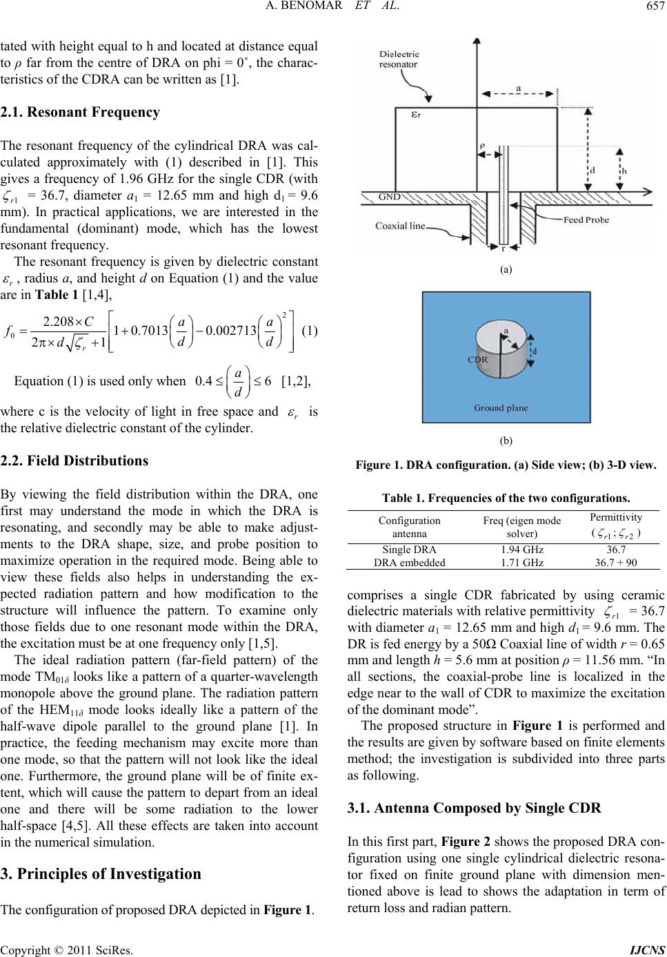 A. BENOMAR ET AL.657 tated with height equal to h and located at distance equal to ρ far from the centre of DRA on phi = 0˚, the charac- teristics of the CDRA can be written as [1]. 2.1. Resonant Frequency The resonant frequency of the cylindrical DRA was cal- culated approximately with (1) described in [1]. This gives a frequency of 1.96 GHz for the single CDR (with 1r = 36.7, diameter a1 = 12.65 mm and high d1 = 9.6 mm). In practical applications, we are interested in the fundamental (dominant) mode, which has the lowest resonant frequency. The resonant frequency is given by dielectric constant r , radius a, and height d on Equation (1) and the value are in Table 1 [1,4], 2 02.208 1 0.70130.002713 21 r Ca fdd d a (1) Equation (1) is u sed only when 0.4 6 a d [1,2], where c is the velocity of light in free space and r is the relative dielectric constant of the cylinder. 2.2. Field Distributions By viewing the field distribution within the DRA, one first may understand the mode in which the DRA is resonating, and secondly may be able to make adjust- ments to the DRA shape, size, and probe position to maximize operation in the required mode. Being able to view these fields also helps in understanding the ex- pected radiation pattern and how modification to the structure will influence the pattern. To examine only those fields due to one resonant mode within the DRA, the excitation must be at one frequency only [1,5]. The ideal radiation pattern (far-field pattern) of the mode TM01δ looks like a pattern of a quarter-wavelength monopole above the ground plane. The radiation pattern of the HEM11δ mode looks ideally like a pattern of the half-wave dipole parallel to the ground plane [1]. In practice, the feeding mechanism may excite more than one mode, so that the pattern will not look like the ideal one. Furthermore, the ground plane will be of finite ex- tent, which will cause the p attern to depart from an ideal one and there will be some radiation to the lower half-space [4,5]. All these effects are taken into account in the numerical simulation. 3. Principles of Investigation (a) (b) Figure 1. DRA configurati; (b) 3-D view. Table 1. Frequencies of the tw o configurations. y on. (a) Side view Configuration Freq (eigen mode Permittivit antenna solver) (1r ;2r ) Single DRA 136.7 .94 GHz D 360 RA embedded1.71 GHz .7 + 9 omprises a single CDR fabricated by using ceramic c dielectric materials with relative permittivity 1r = 36.7 with diameter a1 = 12.65 mm and high d1 = 9m. The DR is fed energy by a 50Ω Coaxial line of width r = 0.65 mm and length h = 5.6 mm at position ρ = 11.56 mm. “In all sections, the coaxial-probe line is localized in the edge near to the wall of CDR to maximize the excitatio n of the dominant mode”. The proposed structure .6 m in Figure 1 is performed and th .1. Antenna Composed by Single CDR this first part, Figure 2 shows the propo sed DRA con- e results are given by software based on finite elements method; the investigation is subdivided into three parts as following. 3 In figuration using one single cylindrical dielectric resona- tor fixed on finite ground plane with dimension men- tioned above is lead to shows the adaptation in term of return loss and radian pattern. The configuration of proposed DRA depicted in Figure 1. Copyright © 2011 SciRes. IJCNS 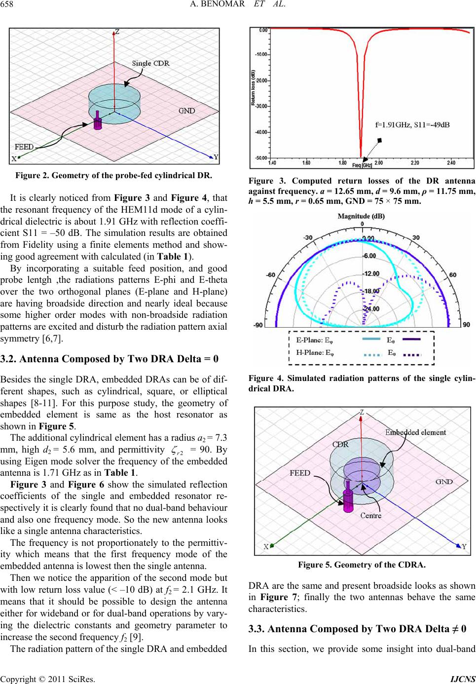 A. BENOMAR ET AL. 658 Figure 2. Geometry of the probe-fed cylindrical DR. It is clearly noticed from Figure 3 and Figure 4, that th good pr y Two DRA Delta = 0 f- drical element has a radius a2 = 7.3 m e resonant frequency of the HEM11d mode of a cylin- drical dielectric is about 1.91 GHz with reflection coeffi- cient S11 = –50 dB. The simulation results are obtained from Fidelity using a finite elements method and show- ing good agreement with calculated (in Table 1). By incorporating a suitable feed position, and obe lentgh ,the radiations patterns E-phi and E-theta over the two orthogonal planes (E-plane and H-plane) are having broadside direction and nearly ideal because some higher order modes with non-broadside radiation patterns are excited and disturb th e radiation p attern axial symmetry [6,7]. 3.2. Antenna Composed b Besides the single DRA, embedded DRAs can be of di ferent shapes, such as cylindrical, square, or elliptical shapes [8-11]. For this purpose study, the geometry of embedded element is same as the host resonator as shown in Figure 5. The additional cylin m, high d2 = 5.6 mm, and permittivity 2r = 90. By using Eigen mode solver the frequency of embedded antenna is 1.71 GHz as in Table 1. Figure 3 and Figure 6 show the s the imulated reflection co ly to the permittiv- ity but w RA and embedded efficients of the single and embedded resonator re- spectively it is clearly found that no dual-band behaviour and also one frequency mode. So the new antenna looks like a single antenna ch aracteristics. The frequency is not proportionate which means that the first frequency mode of the embedded antenna is lowest then the single antenna. Then we notice the apparition of the second mode ith low return loss value (< –10 dB) at f2 = 2.1 GHz. It means that it should be possible to design the antenna either for wideband or for dual-band operations by vary- ing the dielectric constants and geometry parameter to increase the second frequency f2 [9]. The radiation pa t t ern of t he singl e D Figure 3. Computed return losses of the DR antenna against frequency. a = 12.65 mm, d = 9.6 mm, ρ = 11.75 mm, h = 5.5 mm, r = 0.65 mm, GND = 75 × 75 mm. Figure 4. Simulated radiation patterns of the single cylin- drical DRA. Figure 5. Geometry of the CDRA. DRA are the same and present broadside looks as shown y Two DRA Delta ≠ 0 d in Figure 7; finally the two antennas behave the same characteristics. 3.3. Antenna Composed b In this section, we provide some insight into dual-ban Copyright © 2011 SciRes. IJCNS 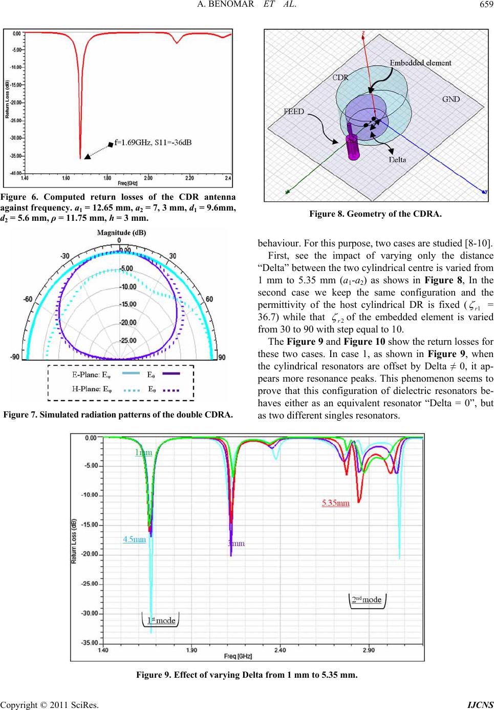 A. BENOMAR ET AL. Copyright © 2011 SciRes. IJCNS 659 Figure 6. Computed return losses of the CDR antenna against frequency. a1 = 12.65 mm, a2 = 7, 3 mm, d1 = 9.6mm, d2 = 5.6 mm, ρ = 11.75 mm, h = 3 mm. Figure 8. Geometry of the CDRA. behaviour. For this purpose, two cases are studied [8-10]. First, see the impact of varying only the distance “Delta” between the two cylin drical centre is varied from 1 mm to 5.35 mm (a1-a2) as shows in Figure 8, In the second case we keep the same configuration and the permittivity of the host cylindrical DR is fixed (1r = 36.7) while that 2r of the embedded element is varied from 30 to 90 with step equal to 10. The Figure 9 and Figure 10 show the return losses for these two cases. In case 1, as shown in Figure 9, when the cylindrical resonators are offset by Delta ≠ 0, it ap- pears more resonance peaks. This phenomenon seems to prove that this configuration of dielectric resonators be- haves either as an equivalent resonator “Delta = 0”, but as two different singles resonators. Figure 7. Simulated radiation patterns of th e double CDRA. Figure 9. Effect of varying Delta from 1 mm to 5.35 mm. 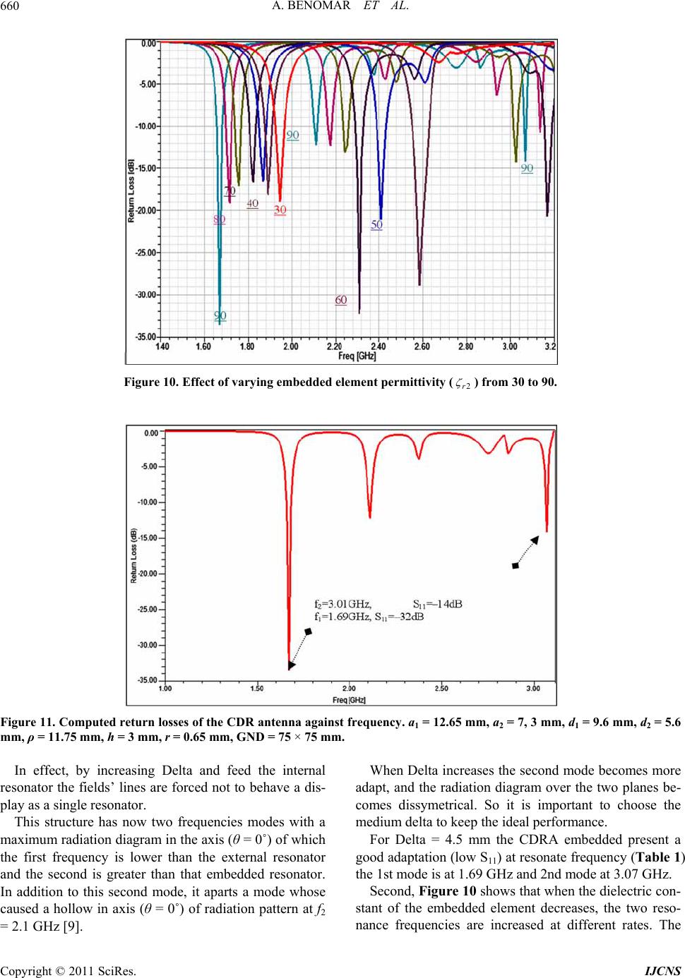 A. BENOMAR ET AL. 660 Figure 10. Effect of varying embedded element permittivity (2r ) from 30 to 90 . Figure 11. Computed return losses of the CDR antenna against frequency. a1 = 12.65 mm, a2 = 7, 3 mm, d1 = 9.6 mm, d2 = 5.6 In effect, by increasing Delta and feed the internal re wo frequencies modes with a m = 2.1 GHz [9]. When Delta increases the second mode becomes more trical. So it is important to choose the m 07 GHz. mm, ρ = 11.75 mm, h = 3 mm, r = 0.65 mm, GND = 75 × 75 mm. sonator the fields’ lines are forced not to behave a dis- play as a single resonator. This structure has now t aximum radiation diagram in the axis (θ = 0˚) of which the first frequency is lower than the external resonator and the second is greater than that embedded resonator. In addition to this second mode, it aparts a mode whose caused a hollow in axis (θ = 0˚) of radiation pattern at f2 adapt, and the radiation diagram over the two planes be- comes dissyme edium delta to keep the ideal performance. For Delta = 4.5 mm the CDRA embedded present a good adaptation (low S11) at resonate frequency (Table 1) the 1st mode is at 1.69 GHz and 2nd mode at 3. Second, Figure 10 shows that when the dielectric con- stant of the embedded element decreases, the two reso- nance frequencies are increased at different rates. The Copyright © 2011 SciRes. IJCNS 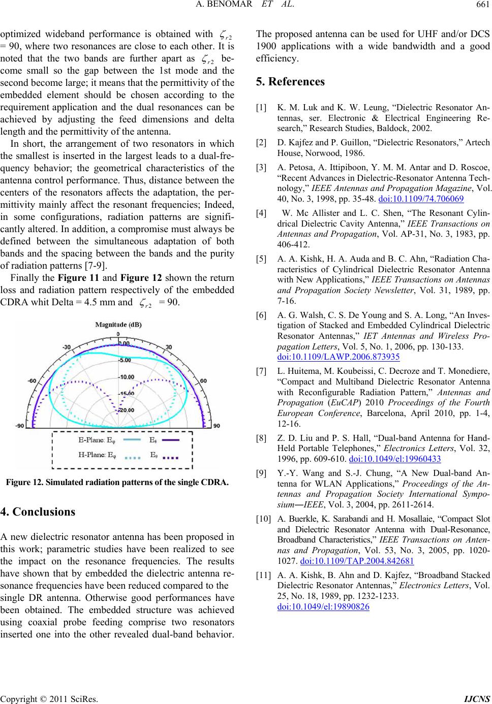 A. BENOMAR ET AL.661 optimized wideband performance is obtained with 2r = 90, where two resonances are close to each other. It is noted that the two bands are further apart as 2r be- come small so the gap between the 1st mode and second become large; it means that the permittivity of the embedded element should be chosen according the requirement application and the dual resonances can be achieved by adjusting the feed dimensions and delta length and the permittivity of the an tenna. In short, the arrangement of two resonators in which the smallest is inserted in the largest leads to a dual-fre- quency behavior; the geometrical charact the to eristics of an and the tenna control performance. Thus, distance between the centers of the resonators affects the adaptation, the per- mittivity mainly affect the resonant frequencies; Indeed, in some configurations, radiation patterns are signifi- cantly altered. In addition, a co mpromise must always be defined between the simultaneous adaptation of both bands and the spacing between the bands and the purity of radiation patterns [7-9] . Finally the Figure 11 and Figure 12 shown the return loss and radiation pattern respectively of the embedded CDRA whit Delta = 4.5 mm2r = 90. Figure 12. Simulated rad iation patterns of th e single CDRA. 4. Conclusions new dielectric resonator antenna has been proposed studies have been realized to e impact on the resonance frequencies. The results ces K. W. Leung, “Dielectric Resonator An- tennas, ser. Electronic & Electrical Engineering Re- ctric-Resonator Antenna Tech- A in this work; parametricsee th have shown that by embedded the dielectric antenna re- sonance frequencies have been reduced compared to the single DR antenna. Otherwise good performances have been obtained. The embedded structure was achieved using coaxial probe feeding comprise two resonators inserted one into the other revealed dual-band behavior. The proposed antenna can be used for UHF and/or DCS 1900 applications with a wide bandwidth and a good efficiency. 5. Referen [1] K. M. Luk and search,” Research Studies, Baldock, 2002. [2] D. Kajfez and P. Guillon, “Dielectric Resonators,” Artech House, Norwood, 1986. [3] A. Petosa, A. Ittipiboon, Y. M. M. Antar and D. Roscoe, “Recent Advances in Diele nology,” IEEE Antennas and Propagation Magazine, Vol. 40, No. 3, 1998, pp. 35-48. doi:10.1109/74.706069 [4] W. Mc Allister and L. C. Shen, “The Resonant Cylin- drical Dielectric Cavity Antenna,” IEEE Transactions on of Cylindrical Dielectric Resonator Antenna n of Stacked and Embedded Cylindrical Dielectric Antennas and Propagation, Vol. AP-31, No. 3, 1983, pp. 406-412. [5] A. A. Kishk, H. A. Auda and B. C. Ahn, “Radiation Cha- racteristics with New Applications,” IEEE Transactions on Antennas and Propagation Society Newsletter, Vol. 31, 1989, pp. 7-16. [6] A. G. Walsh, C. S. De Young and S. A. Long, “An Inves- tigatio Resonator Antennas,” IET Antennas and Wireless Pro- pagation Letters, Vol. 5, No. 1, 2006, pp. 130-133. doi:10.1109/LAWP.2006.873935 [7] L. Huitema, M. Koubeissi, C. Decroze and T. Mone “Compact and Multiband Dielectridiere, c Resonator Antenna rtable Telephones,” Electronics Letters, Vol. 32, with Reconfigurable Radiation Pattern,” Antennas and Propagation (EuCAP) 2010 Proceedings of the Fourth European Conference, Barcelona, April 2010, pp. 1-4, 12-16. [8] Z. D. Liu and P. S. Hall, “Dual-band Antenna for Hand- Held Po 1996, pp. 609-610. doi:10.1049/el:19960433 [9] Y.-Y. Wang and S.-J. Chung, “A New Dual-band An- tenna for WLAN Applications,” Proceedings of the An- al-Resonance, tennas and Propagation Society International Sympo- sium―IEEE, Vol. 3, 2004, pp. 2611-2614. [10] A. Buerkle, K. Sarabandi and H. Mosallaie, “Compact Slot and Dielectric Resonator Antenna with Du Broadband Characteristics,” IEEE Transactions on Anten- nas and Propagation, Vol. 53, No. 3, 2005, pp. 1020- 1027. doi:10.1109/TAP.2004.842681 [11] A. A. Kishk, B. Ahn and D. Kajfez, “Broadband Stacked Dielectric Resonator Antennas,” Electronics Letters, Vol. 25, No. 18, 1989, pp. 1232-1233. doi:10.1049/el:19890826 Copyright © 2011 SciRes. IJCNS |