

Paper Menu >>
Journal Menu >>
 Optics and Photonics Journal, 2011, 1, 130-136 doi:10.4236/opj.2011.13022 Published Online September 2011 (http://www.SciRP.org/journal/opj) Copyright © 2011 SciRes. OPJ Hybrid Optical Beam-Former in Receiver Mode Pham Q. Thai, Arokiaswami Alphones Nanyang Technological University, Singapore City, Singapore E-mail: [email protected] Received July 6, 2011; revised August 10, 2011; accepted August 22, 2011 Abstract In this paper, an optical beam-former in receiving mode has been proposed and experimentally demonstrated. The requirement in system’s hardware has been dramatically reduced using a hybrid approach between dis- persive and non-dispersive delay. The proposed system is capable of supporting RF signals from L-band to X-band, with large coverage and strong robustness against the grating’s group delay ripples. Keywords: Chirped Fiber Grating, Group Delay Ripple, Microwave Photonics, Optical Phased Array Antennas 1. Introduction Despite having many advantages such as better directivity, higher gain, and beam-steering, traditional electrical con- trolled phase array antennas face serious problems working with large bandwidth RF signals at high fre- quencies. One of the most difficult obstacles to overcome is the “beam-squint” phenomenon. The beam direction of the array changes across the RF signal’s bandwidth. For applications with large bandwidth and high frequency requirements, optical beam-forming is a promising can- didate. Optical beam-formers inherit advantages charac- teristics such as large bandwidth, compactness, light- weight, and immunity to electromagnetic interference. More importantly, they can operate squint-free with wide- band, high frequency signals, thus avoiding the most significant drawback of the traditional electrical beam- formers. Optical beamformers using chirped grating and optical delay lines are among the most prominent approaches for photonic beamforming [1]. However, in the former ap- proach, the supported array size is limited since each element requires one tunable laser [2]. In the later ap- proach, the length of the delay device results in many obstacles [3]. In order to combine the advantages of both approaches, optical beamforming systems using a com- bination of dispersive and non-dispersive delays have been proposed [4-7]. In [8], we have shown a hybrid approach between dispersive and non-dispersive delay for optical beam-former in transmitting mode. The novel system employing that method has dramatically reduced hardware requirements. In this paper, the receiving schematic following our hybrid approach is presented. In our proposed receiver, the number of tunable laser is reduced by more than three times. The number of tunable optical delay line is reduced by two times. The required time delay for both devices is also greatly reduced. Experimental and simulation results have shown that the proposed beam-former can support signals with wide RF bandwidth from L-band to X-band. There were only slight distortions in the simulated radia- tion patterns in comparison with the ideal radiation pat- terns. In [9], preliminary simulations and measurements of the proposed system were reported. In this article, many more details about the simulation radiation patterns and measurement results have been disclosed and discussed, especially about the distortions in radiation patterns. The system in this article has been improved from the previous system discussed in [10]. In [10], the combination of optical signals required intensive fine-tuning to ensure no interference between signals modulated at the same op- tical wavelength. In this paper, the problem has been overcome using polarization beam combiners. Since the proposed system use chirped grating, the ef- fect of group delay ripples (GDR) has also been addressed. As studied in [11,12], the GDR has a strong negative impact on the performance of optical beam-former using chirped grating in transmission operation. The study in [12] also suggested that grating may not be suitable for receiving operation. However, simulations have shown that our proposed hybrid system is more robust against GDR. The paper is organized as described. The proposed 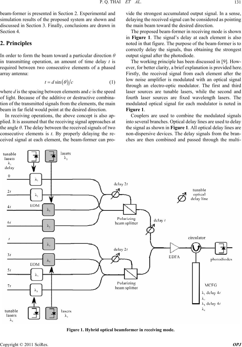 P. Q. THAI ET AL.131 beam-former is presented in Section 2. Experimental and simulation results of the proposed system are shown and discussed in Section 3. Finally, conclusions are drawn in Section 4. 2. Principles In order to form the beam toward a particular direction θ in transmitting operation, an amount of time delay t is required between two consecutive elements of a phased array antenna: sintd c (1) where d is the spacing between elements and c is the speed of light. Because of the additive or destructive combina- tion of the transmitted signals from the elements, the main beam in far field would point at the desired direction. In receiving operations, the above concept is also ap- plied. It is assumed that the receiving signal approaches at the angle θ. The delay between the received signals of two consecutive elements is t. By properly delaying the re- ceived signal at each element, the beam-former can pro- vide the strongest accumulated output signal. In a sense, delaying the received signal can be considered as pointing the main beam toward the desired direction. The proposed beam-former in receiving mode is shown in Figure 1. The signal’s delay at each element is also noted in that figure. The purpose of the beam-former is to correctly delay the signals, thus obtaining the strongest output signal after the photodiode. The working principle has been discussed in [9]. How- ever, for better clarity, a brief explanation is provided here. Firstly, the received signal from each element after the low noise amplifier is modulated with an optical signal through an electro-optic modulator. The first and third laser sources are tunable lasers, while the second and fourth laser sources are fixed wavelength lasers. The modulated optical signal for each modulator is noted in Figure 1. Couplers are used to combine the modulated signals into several branches. Optical delay lines are used to delay the signal as shown in Figure 1. All optical delay lines are non-dispersive devices. The delay signals from the bran- ches are then combined and passed through the multi- Figure 1. Hybrid optical beamformer in receiving mode. Copyright © 2011 SciRes. OPJ 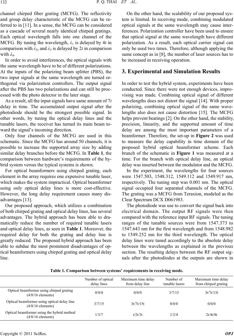 P. Q. THAI ET AL. Copyright © 2011 SciRes. OPJ 132 channel chirped fiber grating (MCFG). The reflectivity and group delay characteristic of the MCFG can be re- ferred to in [11]. In a sense, the MCFG can be considered as a cascade of several nearly identical chirped gratings. Each optical wavelength falls into one channel of the MCFG. By tuning the wavelength, λ1 is delayed by 4t in comparison with λ2, and λ3 is delayed by 2t in comparison with λ4. In order to avoid interferences, the optical signals with the same wavelength have to be of different polarizations. At the inputs of the polarizing beam splitter (PBS), the two input signals at the same wavelength are turned or- thogonal via polarization controllers. The output signal after the PBS has two polarizations and can still be proc- essed with the photo detector in the later stage. As a result, all the input signals have same amount of 7t delay in time. The accumulated output signal after the photodiode should be the strongest possible signal. In other words, by tuning the optical delay lines and the tunable lasers, the receiver has turned its main beam to- ward the signal’s incoming direction. Only four channels of the MCFG are used in this schematic. Since the MCFG has around 50 channels, it is possible to increase the supported array size by adding similar delay branches before the MCFG. In Table 1, the comparison between hardware’s requirements of the hy- brid system versus the typical systems is shown. For optical beamformers using chirped grating, each element in the array requires one expensive tunable laser, which makes the system impractical. Optical beamformer using only optical delay lines is more cost-effective. However, the long delay requirement causes many dis- advantages [13]. Our proposed approach, which utilizes a combination of both chirped grating and optical delay lines, has several advantages. The hybrid approach has been able to dra- matically reduce the number of required tunable lasers and optical delay lines, as seen in Tabl e 1. Moreover, the required delay for both the grating and delay line is greatly reduced. The proposed hybrid approach has been able to subdue the most prominent disadvantages of op- tical beamformers using chirped grating and optical delay line. On the other hand, the scalability of our proposed sys- tem is limited. In receiving mode, combining modulated optical signals at the same wavelength may cause inter- ferences. Polarization controller have been used to ensure that optical signal at the same wavelength have different polarization. As a result, each optical carrier signal can only be used two times. Therefore, although applying the same concept as in [8], the number of laser sources has to be increased in receiving operation. 3. Experimental and Simulation Results In order to test the hybrid system, experiments have been conducted. Since there were not enough devices, impro- vising was made. Combining optical signal of different wavelengths does not distort the signal [14]. With proper polarizing, combining optical signal of the same wave- lengths also does not cause distortion [15]. The MCFG helps prevent beatings [2]. On the other hand, the stability, precision, linearity, and the supported amount of time delay are among the most important parameters of a beamformer. Therefore, the set-up in Figure 2 was used to measure the delay capability in time domain of the proposed hybrid optical beamformer scheme. Each branch of the schematic in Figure 1 was measured at a time. For the branch with optical delay line, an optical delay was inserted between the modulator and the MCFG. In the experiment, the wavelengths for four sources were 1547.503, 1548.312, 1549.112 and 1549.917 nm, respectively. The tuning step was 0.001 nm. The optical signal occupied four separated channels of the MCFG. The grating was a MCFG from Teraxion, modeled as the Clear Spectrum DCX D061983. The photodiode was use to convert the signal back into electrical domain. The output RF signals were then compared with the reference input RF signals. The tuning ranges of the tunable sources were from 1547.373 to 1547.643 nm for the first wavelength and from 1548.982 to 1549.252 nm for the third wavelength. The optical delay lines were tuned accordingly to the absolute delay between the wavelengths as explained in the previous section. The resulting delays between the RF output sig- nals after the photodiodes at the outputs are shown in Table 1. Comparison between systems’ requirements in receiving mode. Number of optical delay lines Maximum time delay from delay line Number of tunable lasers Maximum time delay from chirped grating Optical beamformer using chirped grating (4/8/16 elements) 0/0/0 0/0/0 3/7/15 3t/7t/15t Optical beamformer using optical delay line (4/8/16 elements) 3/7/15 3t/7t/15t 0/0/0 0/0/0 Optical beamformer using the hybrid method (4/8/16 elements) 1/3/7 t/2t/3t 1/2/4 2t/4t/8t 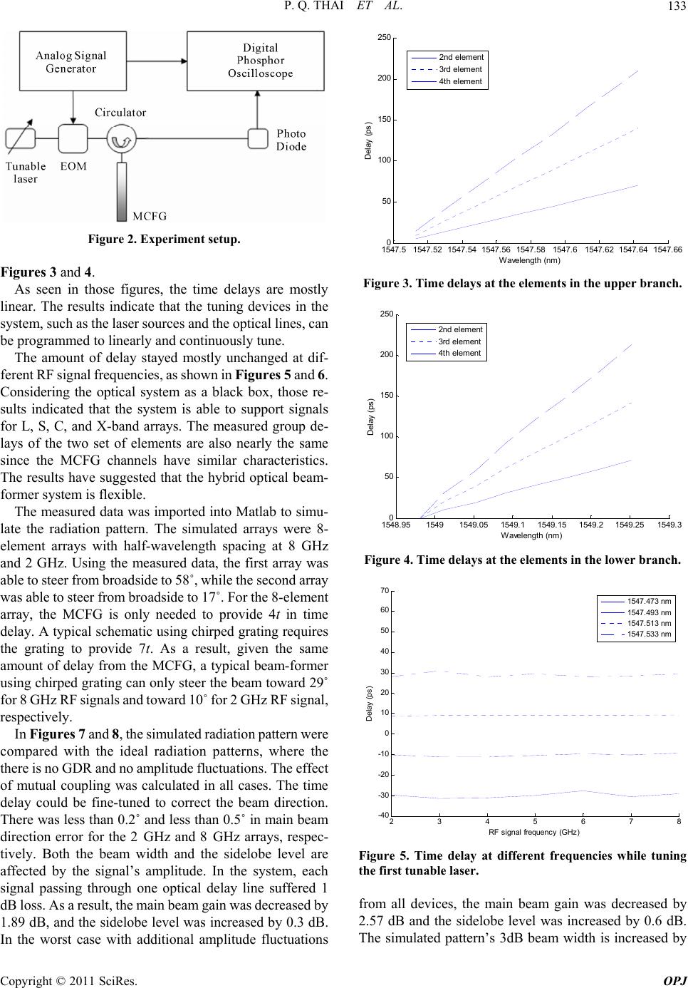 P. Q. THAI ET AL. Copyright © 2011 SciRes. OPJ 133 Figure 2. Experiment setup. Figures 3 and 4. As seen in those figures, the time delays are mostly linear. The results indicate that the tuning devices in the system, such as the laser sources and the optical lines, can be programmed to linearly and continuously tune. The amount of delay stayed mostly unchanged at dif- ferent RF signal frequencies, as shown in Fi gures 5 and 6. Considering the optical system as a black box, those re- sults indicated that the system is able to support signals for L, S, C, and X-band arrays. The measured group de- lays of the two set of elements are also nearly the same since the MCFG channels have similar characteristics. The results have suggested that the hybrid optical beam- former system is flexible. The measured data was imported into Matlab to simu- late the radiation pattern. The simulated arrays were 8- element arrays with half-wavelength spacing at 8 GHz and 2 GHz. Using the measured data, the first array was able to steer from broadside to 58˚, while the second array was able to steer from broadside to 17˚. For the 8-element array, the MCFG is only needed to provide 4t in time delay. A typical schematic using chirped grating requires the grating to provide 7t. As a result, given the same amount of delay from the MCFG, a typical beam-former using chirped grating can only steer the beam toward 29˚ for 8 GHz RF signals and toward 10˚ for 2 GHz RF signal, respectively. In Fi gures 7 and 8, the simulated radiation pattern were compared with the ideal radiation patterns, where the there is no GDR and no amplitude fluctuations. The effect of mutual coupling was calculated in all cases. The time delay could be fine-tuned to correct the beam direction. There was less than 0.2˚ and less than 0.5˚ in main beam direction error for the 2 GHz and 8 GHz arrays, respec- tively. Both the beam width and the sidelobe level are affected by the signal’s amplitude. In the system, each signal passing through one optical delay line suffered 1 dB loss. As a result, the main beam gain was decreased by 1.89 dB, and the sidelobe level was increased by 0.3 dB. In the worst case with additional amplitude fluctuations 1547.5 1547.521547.54 1547.56 1547.581547.61547.62 1547.641547.66 0 50 100 150 200 250 Wavelength (nm) Delay (ps) 2nd element 3rd element 4th el em ent Figure 3. Time delays at the elements in the upper branch. 1548.9515491549.051549.11549.151549.2 1549.251549.3 0 50 100 150 200 250 W a velengt h (nm ) Delay (ps) 2nd el em ent 3rd element 4t h elem ent Figure 4. Time delays at the elements in the lower branch. 2345678 -40 -30 -20 -10 0 10 20 30 40 50 60 70 RF s i gn al frequency (G Hz ) Delay (ps) 1547. 47 3 nm 1547. 49 3 nm 1547. 51 3 nm 1547. 53 3 nm Figure 5. Time delay at different frequencies while tuning the first tunable laser. from all devices, the main beam gain was decreased by 2.57 dB and the sidelobe level was increased by 0.6 dB. The simulated pattern’s 3dB beam width is increased by 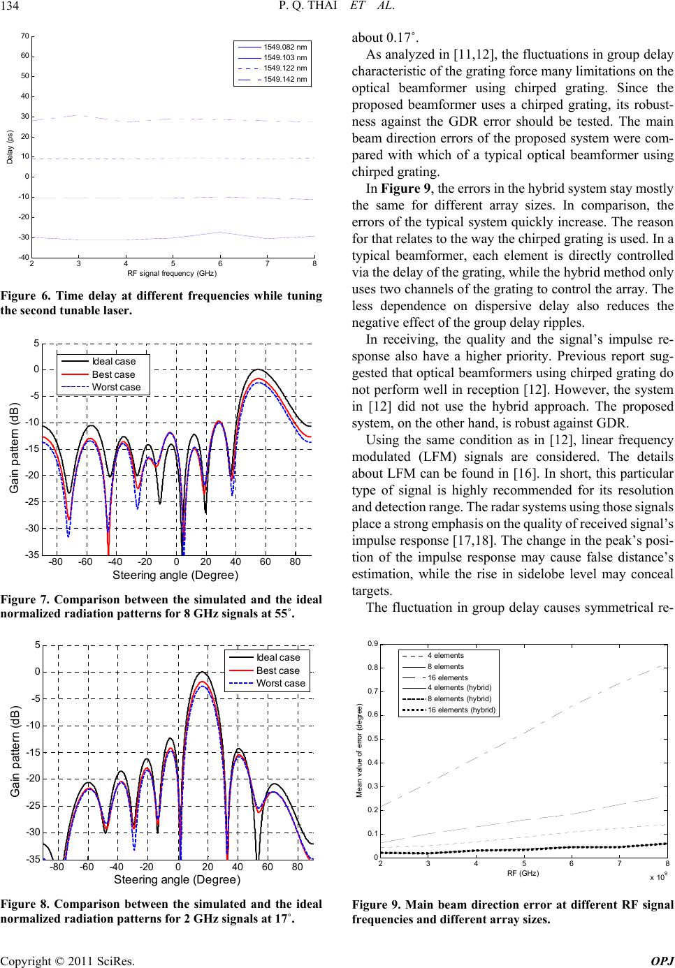 P. Q. THAI ET AL. 134 2345678 -40 -30 -20 -10 0 10 20 30 40 50 60 70 RF si gnal frequency (GHz ) Delay (ps) 1549.082 nm 1549.103 nm 1549.122 nm 1549.142 nm Figure 6. Time delay at different frequencies while tuning the second tunable laser. -80 -60 -40 -20020 40 60 80 -35 -30 -25 -20 -15 -10 -5 0 5 St eering angle ( D egree) Gain pattern (dB) Ideal case Best case Worst case Figure 7. Comparison between the simulated and the ideal normalized radiation patterns for 8 GHz signals at 55˚. -80 -60 -40 -20020 40 60 80 -35 -30 -25 -20 -15 -10 -5 0 5 St e ering a ngle (Degr ee) Gain pattern (dB) Ideal c ase Best case Worst case Figure 8. Comparison between the simulated and the ideal normalized radiation patterns for 2 GHz signals at 17˚. about 0.17˚. As analyzed in [11,12], the fluctuations in group delay characteristic of the grating force many limitations on the optical beamformer using chirped grating. Since the proposed beamformer uses a chirped grating, its robust- ness against the GDR error should be tested. The main beam direction errors of the proposed system were com- pared with which of a typical optical beamformer using chirped grating. In Figure 9, the errors in the hybrid system stay mostly the same for different array sizes. In comparison, the errors of the typical system quickly increase. The reason for that relates to the way the chirped grating is used. In a typical beamformer, each element is directly controlled via the delay of the grating, while the hybrid method only uses two channels of the grating to control the array. The less dependence on dispersive delay also reduces the negative effect of the group delay ripples. In receiving, the quality and the signal’s impulse re- sponse also have a higher priority. Previous report sug- gested that optical beamformers using chirped grating do not perform well in reception [12]. However, the system in [12] did not use the hybrid approach. The proposed system, on the other hand, is robust against GDR. Using the same condition as in [12], linear frequency modulated (LFM) signals are considered. The details about LFM can be found in [16]. In short, this particular type of signal is highly recommended for its resolution and detection range. The radar systems using those signals place a strong emphasis on the quality of received signal’s impulse response [17,18]. The change in the peak’s posi- tion of the impulse response may cause false distance’s estimation, while the rise in sidelobe level may conceal targets. The fluctuation in group delay causes symmetrical re- 23 4 56 7 8 x 10 9 0 0.1 0.2 0.3 0.4 0.5 0.6 0.7 0.8 0.9 RF ( G Hz) Mean v al ue of error (degree) 4 elem e nt s 8 elem e nt s 16 elements 4 elem e nt s (hy b ri d) 8 elem e nt s (hy b ri d) 16 elements (hybrid) Figure 9. Main beam direction error at different RF signal frequencies and different array sizes. Copyright © 2011 SciRes. OPJ 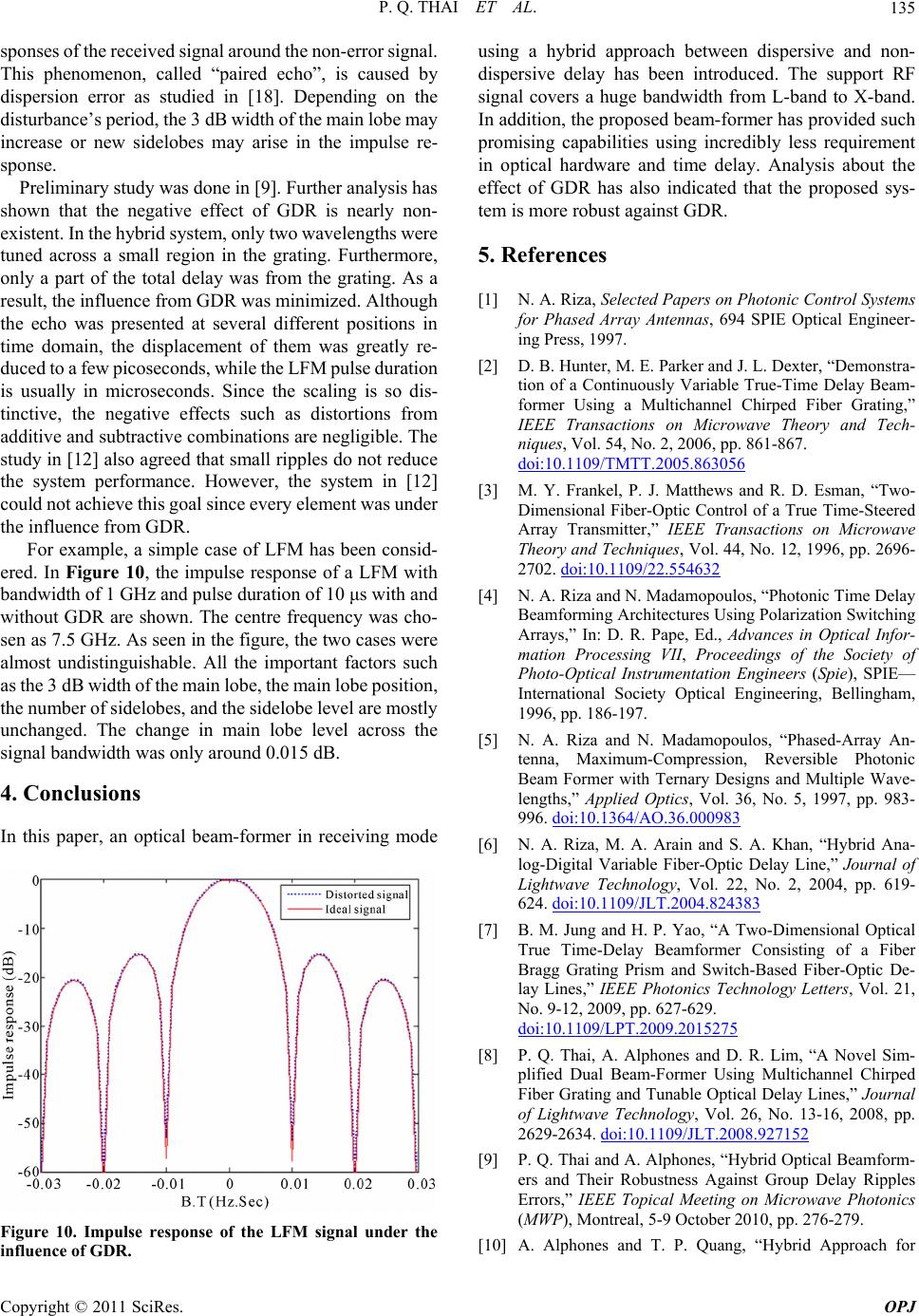 P. Q. THAI ET AL.135 sponses of the received signal around the non-error signal. This phenomenon, called “paired echo”, is caused by dispersion error as studied in [18]. Depending on the disturbance’s period, the 3 dB width of the main lobe may increase or new sidelobes may arise in the impulse re- sponse. Preliminary study was done in [9]. Further analysis has shown that the negative effect of GDR is nearly non- existent. In the hybrid system, only two wavelengths were tuned across a small region in the grating. Furthermore, only a part of the total delay was from the grating. As a result, the influence from GDR was minimized. Although the echo was presented at several different positions in time domain, the displacement of them was greatly re- duced to a few picoseconds, while the LFM pulse duration is usually in microseconds. Since the scaling is so dis- tinctive, the negative effects such as distortions from additive and subtractive combinations are negligible. The study in [12] also agreed that small ripples do not reduce the system performance. However, the system in [12] could not achieve this goal since every element was under the influence from GDR. For example, a simple case of LFM has been consid- ered. In Figure 10, the impulse response of a LFM with bandwidth of 1 GHz and pulse duration of 10 μs with and without GDR are shown. The centre frequency was cho- sen as 7.5 GHz. As seen in the figure, the two cases were almost undistinguishable. All the important factors such as the 3 dB width of the main lobe, the main lobe position, the number of sidelobes, and the sidelobe level are mostly unchanged. The change in main lobe level across the signal bandwidth was only around 0.015 dB. 4. Conclusions In this paper, an optical beam-former in receiving mode Figure 10. Impulse response of the LFM signal under the influence of GDR. using a hybrid approach between dispersive and non- dispersive delay has been introduced. The support RF signal covers a huge bandwidth from L-band to X-band. In addition, the proposed beam-former has provided such promising capabilities using incredibly less requirement in optical hardware and time delay. Analysis about the effect of GDR has also indicated that the proposed sys- tem is more robust against GDR. 5. References [1] N. A. Riza, Selected Papers on Photonic Control Systems for Phased Array Antennas, 694 SPIE Optical Engineer- ing Press, 1997. [2] D. B. Hunter, M. E. Parker and J. L. Dexter, “Demonstra- tion of a Continuously Variable True-Time Delay Beam- former Using a Multichannel Chirped Fiber Grating,” IEEE Transactions on Microwave Theory and Tech- niques, Vol. 54, No. 2, 2006, pp. 861-867. doi:10.1109/TMTT.2005.863056 [3] M. Y. Frankel, P. J. Matthews and R. D. Esman, “Two- Dimensional Fiber-Optic Control of a True Time-Steered Array Transmitter,” IEEE Transactions on Microwave Theory and Techniques, Vol. 44, No. 12, 1996, pp. 2696- 2702. doi:10.1109/22.554632 [4] N. A. Riza and N. Madamopoulos, “Photonic Time Delay Beamforming Architectures Using Polarization Switching Arrays,” In: D. R. Pape, Ed., Advances in Optical Infor- mation Processing VII, Proceedings of the Society of Photo-Optical Instrumentation Engineers (Spie), SPIE— International Society Optical Engineering, Bellingham, 1996, pp. 186-197. [5] N. A. Riza and N. Madamopoulos, “Phased-Array An- tenna, Maximum-Compression, Reversible Photonic Beam Former with Ternary Designs and Multiple Wave- lengths,” Applied Optics, Vol. 36, No. 5, 1997, pp. 983- 996. doi:10.1364/AO.36.000983 [6] N. A. Riza, M. A. Arain and S. A. Khan, “Hybrid Ana- log-Digital Variable Fiber-Optic Delay Line,” Journal of Lightwave Technology, Vol. 22, No. 2, 2004, pp. 619- 624. doi:10.1109/JLT.2004.824383 [7] B. M. Jung and H. P. Yao, “A Two-Dimensional Optical True Time-Delay Beamformer Consisting of a Fiber Bragg Grating Prism and Switch-Based Fiber-Optic De- lay Lines,” IEEE Photonics Technology Letters, Vol. 21, No. 9-12, 2009, pp. 627-629. doi:10.1109/LPT.2009.2015275 [8] P. Q. Thai, A. Alphones and D. R. Lim, “A Novel Sim- plified Dual Beam-Former Using Multichannel Chirped Fiber Grating and Tunable Optical Delay Lines,” Journal of Lightwave Technology, Vol. 26, No. 13-16, 2008, pp. 2629-2634. doi:10.1109/JLT.2008.927152 [9] P. Q. Thai and A. Alphones, “Hybrid Optical Beamform- ers and Their Robustness Against Group Delay Ripples Errors,” IEEE Topical Meeting on Microwave Photonics (MWP), Montreal, 5-9 October 2010, pp. 276-279. [10] A. Alphones and T. P. Quang, “Hybrid Approach for Copyright © 2011 SciRes. OPJ 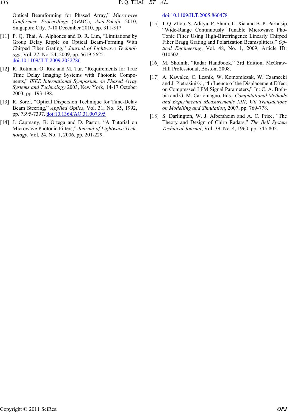 P. Q. THAI ET AL. Copyright © 2011 SciRes. OPJ 136 Optical Beamforming for Phased Array,” Microwave Conference Proceedings (APMC), Asia-Pacific 2010, Singapore City, 7-10 December 2010, pp. 311-317. [11] P. Q. Thai, A. Alphones and D. R. Lim, “Limitations by Group Delay Ripple on Optical Beam-Forming With Chirped Fiber Grating,” Journal of Lightwave Technol- ogy, Vol. 27, No. 24, 2009, pp. 5619-5625. doi:10.1109/JLT.2009.2032786 [12] R. Rotman, O. Raz and M. Tur, “Requirements for True Time Delay Imaging Systems with Photonic Compo- nents,” IEEE International Symposium on Phased Array Systems and Technology 2003, New York, 14-17 October 2003, pp. 193-198. [13] R. Soref, “Optical Dispersion Technique for Time-Delay Beam Steering,” Applied Optics, Vol. 31, No. 35, 1992, pp. 7395-7397. doi:10.1364/AO.31.007395 [14] J. Capmany, B. Ortega and D. Pastor, “A Tutorial on Microwave Photonic Filters,” Journal of Lightwave Tech- nology, Vol. 24, No. 1, 2006, pp. 201-229. doi:10.1109/JLT.2005.860478 [15] J. Q. Zhou, S. Aditya, P. Shum, L. Xia and B. P. Parhusip, “Wide-Range Continuously Tunable Microwave Pho- Tonic Filter Using High-Birefringence Linearly Chirped Fiber Bragg Grating and Polarization Beamsplitters,” Op- tical Engineering, Vol. 48, No. 1, 2009, Article ID: 010502. [16] M. Skolnik, “Radar Handbook,” 3rd Edition, McGraw- Hill Professional, Boston, 2008. [17] A. Kawalec, C. Lesnik, W. Komomiczak, W. Czamecki and J. Pietrasiniski, “Influence of the Displacement Effect on Compressed LFM Signal Parameters,” In: C. A. Breb- bia and G. M. Carlomagno, Eds., Computational Methods and Experimental Measurements XIII, Wit Transactions on Modelling and Simulation, 2007, pp. 769-778. [18] S. Darlington, W. J. Albersheim and A. C. Price, “The Theory and Design of Chirp Radars,” The Bell System Technical Journal, Vol. 39, No. 4, 1960, pp. 745-802. |