

Paper Menu >>
Journal Menu >>
 Energy and Power En gi neering, 2011, 3, 490-498 doi:10.4236/epe.2011.34059 Published Online September 2011 (http://www.SciRP.org/journal/epe) Copyright © 2011 SciRes. EPE Mechanism Analysis on Str e ss Accumulation in Cylindrical Vertical-Placed Metal Hydride Reactor Xiaochen Hu, Zhaogang Qi, Feng Qin, Jiangping Chen Institute of Refrigeration and Cryogenics Engineering, Shanghai Jiao Tong University, Shanghai, China E-mail: [email protected] Received June 29, 2011; revised July 30, 2011; accepted August 15, 2011 Abstract It’s known that the pulverization-densification mechanism of metal hydride may cause the stress accumula- tion in metal hydrides reactors. In this paper, this idea is proved based on granulometry and a new idea of cycling compression effect is presented, which is caused by the friction between wall and metal hydrides. Through theoretical analysis, the cycling compression effects is shown to increase the localized packing rate from top to down in vertical-placed reactors and thus lead to the maximum deformation in the bottom of re- actors, proving that it is the interaction of pulverization-densification effect and cycling compression effect resulting in the stress problems of vertical-placed reactors. Further study points that the effective methods relieving the cycling compress effect are to decrease hydrogen absorption/desorption cycle number, slender- ness ratio of reactor, wall friction factor and initial packing rate, or to lower the thermal conductivity and the volume expansion coefficient of metal hydrides. Keywords: Metal Hydride, Stress Accumulation, Pulverization, Densification 1. Introduction The pulverization and expansion of metal hydrides during its absorption/desorption cycles could decrease the reliabil- ity of the reactor directly and greatly, becoming one of the key obstacles to the development and application of hy- drogen energy. Many studies have been done to explain and solve this problem. In Nakamura Y. et al.’s study, the expansion ratio for AB5 type metal hydrides can be larger than 1.2 during the hydrogen absorption, being the domi- nant factors in the intrinsic powder degradation [1]. B. Y. Ao et al. also found in their test that the LaNi5 alloy’s vol- ume expansion ratio was up to 24% after absorbing hydro- gen, causing the density of alloy from the top to bottom of the bed higher and higher and thus the stress greater and greater after several cycles [2]. They indicated that the in- crease of initial packing rate and decrease of the wall thickness could help relieving the stress accumulation. Na- sako K. et al. presented that the localized stress would be generated at the bottom of the reactor with an alloy packing rate of 40% (v/v), and increased with each absorption/de- sorption cycle [3]. They then proved that the stress accu- mulation depend on the amount of hydrogen absorption/ desorption cycles and on the initial packing rate. Other experimental studies also proved that the actual stress could rise up acutely with the increase of localized relative den- sity, depth of reactor and cycle number et al. [4-6]. As a conclusion, the pulverization-densification mechanism is proposed and widely accepted: during the process of hy- drogen absorption/desorption cycles, since the metal hy- drides powder is crushing up gradually, the finer and finer particles becomes gathering into to the bottom of the reac- tor under the pull of gravity, which finally cause the local- ize relative density of metal hydrides powder to increase and self-densification to take place after several repeated manner [4]. Hence, in order to smooth the expansion of metal hydrides and the congestion of stress, researchers have carried out a lot of attempt, for example, designing special construction of reactor, like “rabloc” and “free space” in the reactor advised by Block F. R. et al. [7] and Bernauer O. et al. [8], respectively. Although a lot of investigations have indicated that the stress accumulation is clarified by the pulverization- densification of metal hydrides and the absorption/de- sorption cycles, few surveys have been presented about the reason how the absorption/desorption cycles could help the concentration of stress. In this study, a new idea of cycling compression effect is proposed to explain the principle of absorption/desorption cycles on the stress accumulation. Cycling compression effect is caused by 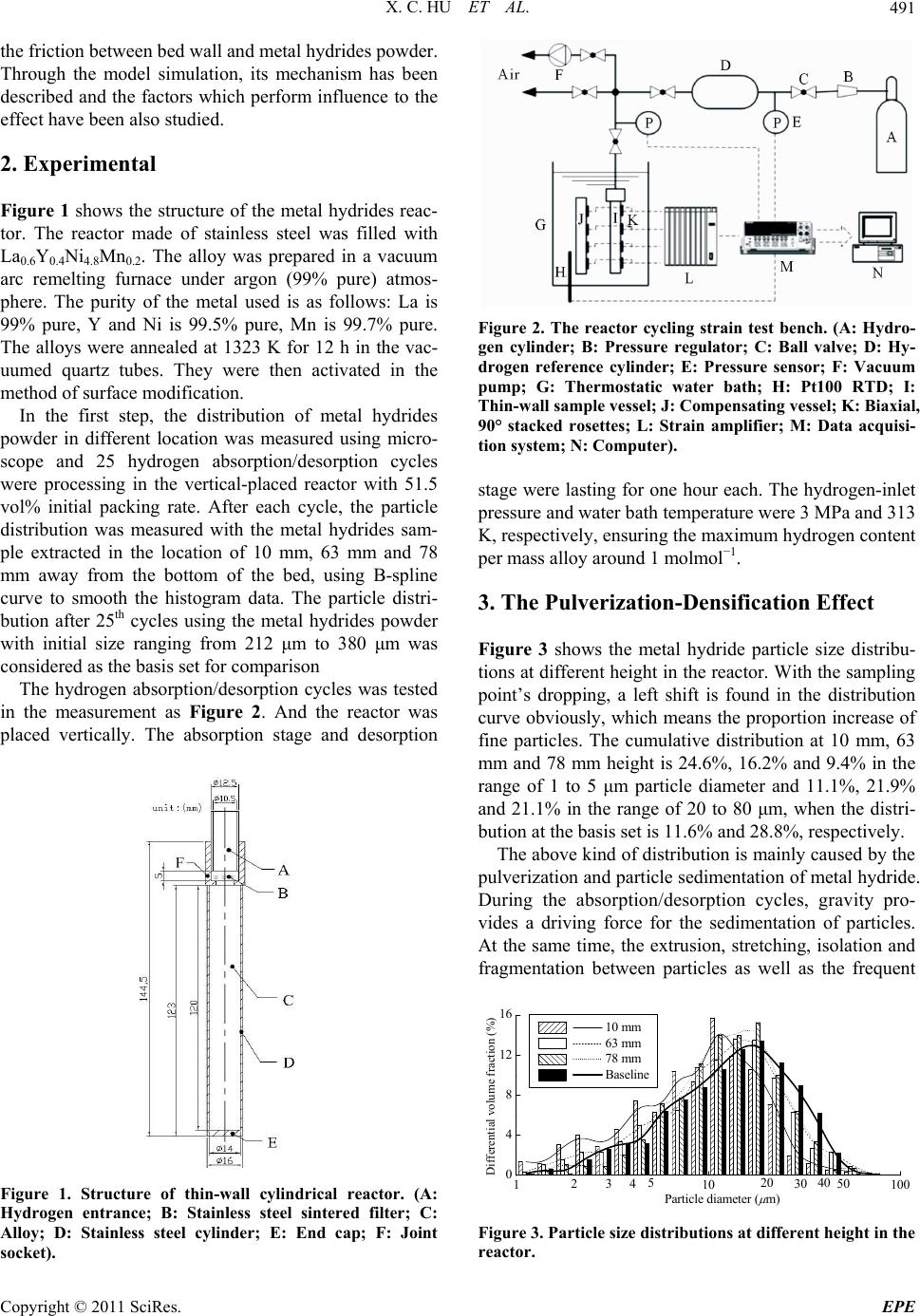 X. C. HU ET AL.491 the friction between bed wall and metal hydrides powder. Through the model simulation, its mechanism has been described and the factors which perform influence to the effect have been also studied. 2. Experimental Figure 1 shows the structure of the metal hydrides reac- tor. The reactor made of stainless steel was filled with La0.6Y0.4Ni4.8Mn0.2. The alloy was prepared in a vacuum arc remelting furnace under argon (99% pure) atmos- phere. The purity of the metal used is as follows: La is 99% pure, Y and Ni is 99.5% pure, Mn is 99.7% pure. The alloys were annealed at 1323 K for 12 h in the vac- uumed quartz tubes. They were then activated in the method of surface modification. In the first step, the distribution of metal hydrides powder in different location was measured using micro- scope and 25 hydrogen absorption/desorption cycles were processing in the vertical-placed reactor with 51.5 vol% initial packing rate. After each cycle, the particle distribution was measured with the metal hydrides sam- ple extracted in the location of 10 mm, 63 mm and 78 mm away from the bottom of the bed, using B-spline curve to smooth the histogram data. The particle distri- bution after 25th cycles using the metal hydrides powder with initial size ranging from 212 μm to 380 μm was considered as the basis set for comparison The hydrogen absorption/desorption cycles was tested in the measurement as Figure 2. And the reactor was placed vertically. The absorption stage and desorption Figure 1. Structure of thin-wall cylindrical reactor. (A: Hydrogen entrance; B: Stainless steel sintered filter; C: Alloy; D: Stainless steel cylinder; E: End cap; F: Joint socket). Figure 2. The reactor cycling strain test bench. (A: Hydro- gen cylinder; B: Pressure regulator; C: Ball valve; D: Hy- drogen reference cylinder; E: Pressure sensor; F: Vacuum pump; G: Thermostatic water bath; H: Pt100 RTD; I: Thin-wall sample vessel; J: Compensating vessel; K: Biaxial, 90° stacked rosettes; L: Strain amplifier; M: Data acquisi- tion system; N: Computer). stage were lasting for one hour each. The hydrogen-inlet pressure and water bath temperature were 3 MPa and 313 K, respectively, ensuring the maximum hydrogen content per mass alloy around 1 molmol−1. 3. The Pulverization-Densification Effect Figure 3 shows the metal hydride particle size distribu- tions at different height in the reactor. With the sampling point’s dropping, a left shift is found in the distribution curve obviously, which means the proportion increase of fine particles. The cumulative distribution at 10 mm, 63 mm and 78 mm height is 24.6%, 16.2% and 9.4% in the range of 1 to 5 μm particle diameter and 11.1%, 21.9% and 21.1% in the range of 20 to 80 μm, when the distri- bution at the basis set is 11.6% and 28.8%, respectively. The above kind of distribution is mainly caused by the pulverization and particle sedimentation of metal hydride. During the absorption/desorption cycles, gravity pro- vides a driving force for the sedimentation of particles. At the same time, the extrusion, stretching, isolation and fragmentation between particles as well as the frequent 110100 0 4 8 12 16 Differential volume fraction (%) Particle diameter ( m) 10 mm 63 mm 78 mm Baseline 40 30 20 42 5035 Figure 3. Particle size distributions at different height in the reactor. Copyright © 2011 SciRes. EPE 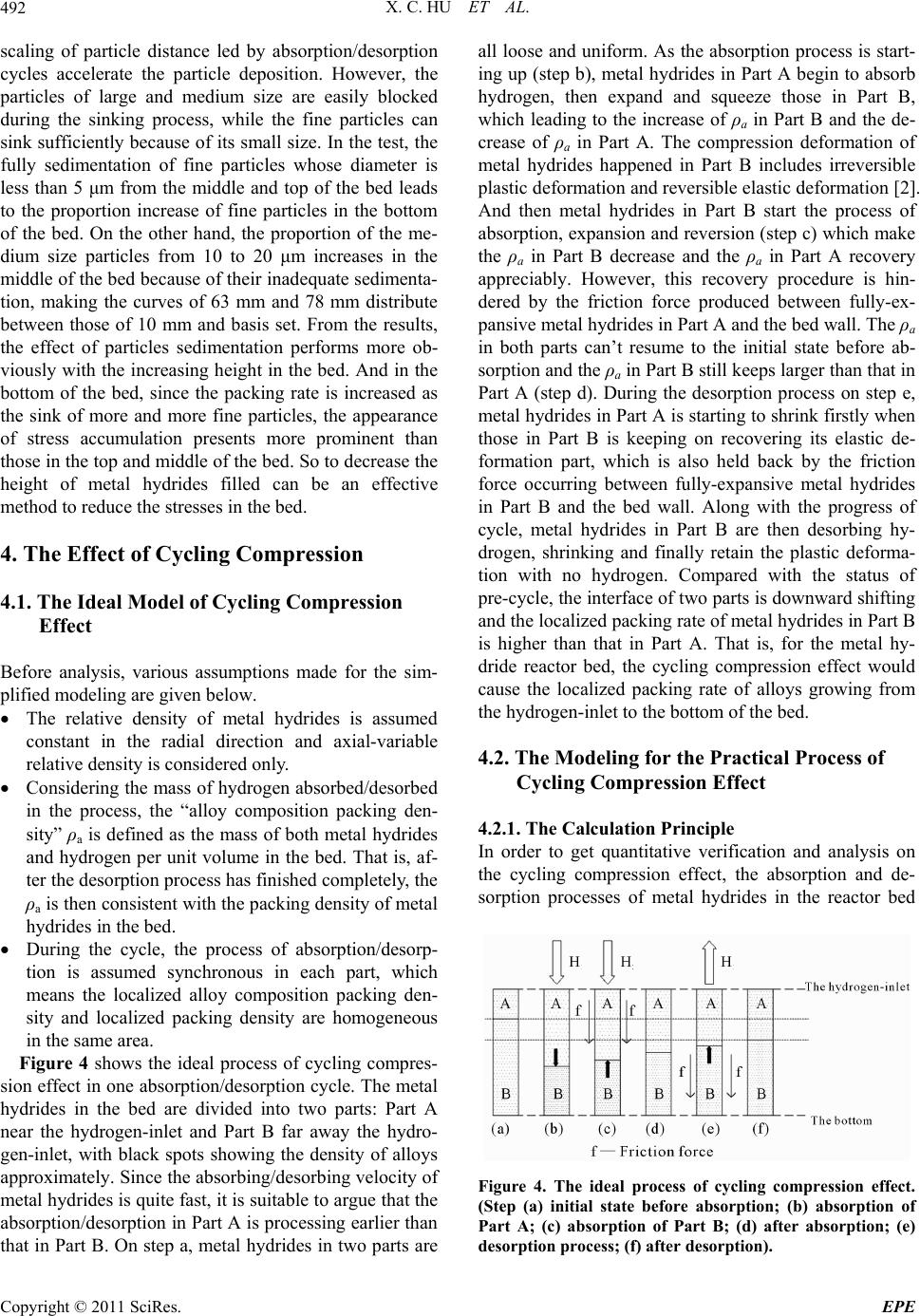 X. C. HU ET AL. 492 scaling of particle distance led by absorption/desorption cycles accelerate the particle deposition. However, the particles of large and medium size are easily blocked during the sinking process, while the fine particles can sink sufficiently because of its small size. In the test, the fully sedimentation of fine particles whose diameter is less than 5 μm from the middle and top of the bed leads to the proportion increase of fine particles in the bottom of the bed. On the other hand, the proportion of the me- dium size particles from 10 to 20 μm increases in the middle of the bed because of their inadequate sedimenta- tion, making the curves of 63 mm and 78 mm distribute between those of 10 mm and basis set. From the results, the effect of particles sedimentation performs more ob- viously with the increasing height in the bed. And in the bottom of the bed, since the packing rate is increased as the sink of more and more fine particles, the appearance of stress accumulation presents more prominent than those in the top and middle of the bed. So to decrease the height of metal hydrides filled can be an effective method to reduce the stresses in the bed. 4. The Effect of Cycling Compression 4.1. The Ideal Model of Cycling Compression Effect Before analysis, various assumptions made for the sim- plified modeling are given below. The relative density of metal hydrides is assumed constant in the radial direction and axial-variable relative density is considered only. Considering the mass of hydrogen absorbed/desorbed in the process, the “alloy composition packing den- sity” ρa is defined as the mass of both metal hydrides and hydrogen per unit volume in the bed. That is, af- ter the desorption process has finished completely, the ρa is then consistent with the packing density of metal hydrides in the bed. During the cycle, the process of absorption/desorp- tion is assumed synchronous in each part, which means the localized alloy composition packing den- sity and localized packing density are homogeneous in the same area. Figure 4 shows the ideal process of cycling compres- sion effect in one absorption/desorption cycle. The metal hydrides in the bed are divided into two parts: Part A near the hydrogen-inlet and Part B far away the hydro- gen-inlet, with black spots showing the density of alloys approximately. Since the absorbing/desorbing velocity of metal hydrides is quite fast, it is suitable to argue that the absorption/desorption in Part A is processing earlier than that in Part B. On step a, metal hydrides in two parts are all loose and uniform. As the absorption process is start- ing up (step b), metal hydrides in Part A begin to absorb hydrogen, then expand and squeeze those in Part B, which leading to the increase of ρa in Part B and the de- crease of ρa in Part A. The compression deformation of metal hydrides happened in Part B includes irreversible plastic deformation and reversible elastic deformation [2]. And then metal hydrides in Part B start the process of absorption, expansion and reversion (step c) which make the ρa in Part B decrease and the ρa in Part A recovery appreciably. However, this recovery procedure is hin- dered by the friction force produced between fully-ex- pansive metal hydrides in Part A and the bed wall. The ρa in both parts can’t resume to the initial state before ab- sorption and the ρa in Part B still keeps larger than that in Part A (step d). During the desorption process on step e, metal hydrides in Part A is starting to shrink firstly when those in Part B is keeping on recovering its elastic de- formation part, which is also held back by the friction force occurring between fully-expansive metal hydrides in Part B and the bed wall. Along with the progress of cycle, metal hydrides in Part B are then desorbing hy- drogen, shrinking and finally retain the plastic deforma- tion with no hydrogen. Compared with the status of pre-cycle, the interface of two parts is downward shifting and the localized packing rate of metal hydrides in Part B is higher than that in Part A. That is, for the metal hy- dride reactor bed, the cycling compression effect would cause the localized packing rate of alloys growing from the hydrogen-inlet to the bottom of the bed. 4.2. The Modeling for the Practical Process of Cycling Compression Effect 4.2.1. The Calculation Principle In order to get quantitative verification and analysis on the cycling compression effect, the absorption and de- sorption processes of metal hydrides in the reactor bed Figure 4. The ideal process of cycling compression effect. (Step (a) initial state before absorption; (b) absorption of Part A; (c) absorption of Part B; (d) after absorption; (e) desorption process; (f) after desorption). Copyright © 2011 SciRes. EPE 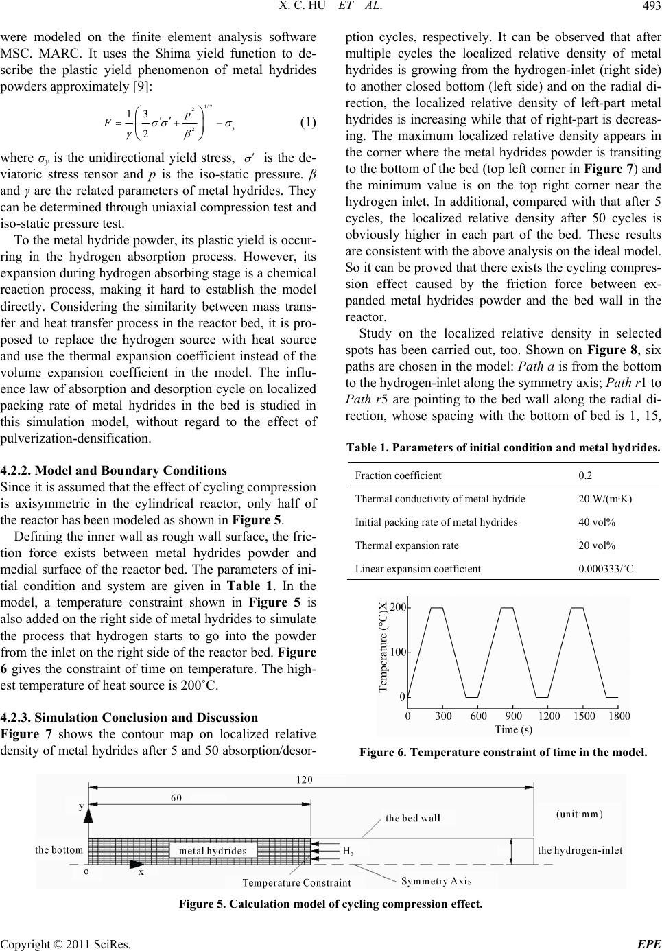 X. C. HU ET AL. Copyright © 2011 SciRes. EPE 493 ption cycles, respectively. It can be observed that after multiple cycles the localized relative density of metal hydrides is growing from the hydrogen-inlet (right side) to another closed bottom (left side) and on the radial di- rection, the localized relative density of left-part metal hydrides is increasing while that of right-part is decreas- ing. The maximum localized relative density appears in the corner where the metal hydrides powder is transiting to the bottom of the bed (top left corner in Figure 7) and the minimum value is on the top right corner near the hydrogen inlet. In additional, compared with that after 5 cycles, the localized relative density after 50 cycles is obviously higher in each part of the bed. These results are consistent with the above analysis on the ideal model. So it can be proved that there exists the cycling compres- sion effect caused by the friction force between ex- panded metal hydrides powder and the bed wall in the reactor. were modeled on the finite element analysis software MSC. MARC. It uses the Shima yield function to de- scribe the plastic yield phenomenon of metal hydrides powders approximately [9]: 1/2 2 2 13 2y p F (1) where σy is the unidirectional yield stress, is the de- viatoric stress tensor and p is the iso-static pressure. β and γ are the related parameters of metal hydrides. They can be determined through uniaxial compression test and iso-static pressure test. To the metal hydride powder, its plastic yield is occur- ring in the hydrogen absorption process. However, its expansion during hydrogen absorbing stage is a chemical reaction process, making it hard to establish the model directly. Considering the similarity between mass trans- fer and heat transfer process in the reactor bed, it is pro- posed to replace the hydrogen source with heat source and use the thermal expansion coefficient instead of the volume expansion coefficient in the model. The influ- ence law of absorption and desorption cycle on localized packing rate of metal hydrides in the bed is studied in this simulation model, without regard to the effect of pulverization-densification. Study on the localized relative density in selected spots has been carried out, too. Shown on Figure 8, six paths are chosen in the model: Path a is from the bottom to the hydrogen-inlet along the symmetry axis; Path r1 to Path r5 are pointing to the bed wall along the radial di- rection, whose spacing with the bottom of bed is 1, 15, Table 1. Parameters of initial condition and metal hydrides. 4.2.2. Model and Boundary Co ndi tions Fraction coefficient 0.2 Thermal conductivity of metal hydride 20 W/(m·K) Initial packing rate of metal hydrides 40 vol% Thermal expansion rate 20 vol% Linear expansion coefficient 0.000333/˚C Since it is assumed that the effect of cycling compression is axisymmetric in the cylindrical reactor, only half of the reactor has been modeled as shown in Figure 5. Defining the inner wall as rough wall surface, the fric- tion force exists between metal hydrides powder and medial surface of the reactor bed. The parameters of ini- tial condition and system are given in Table 1. In the model, a temperature constraint shown in Figure 5 is also added on the right side of metal hydrides to simulate the process that hydrogen starts to go into the powder from the inlet on the right side of the reactor bed. Figure 6 gives the constraint of time on temperature. The high- est temperature of heat source is 200˚C. 4.2.3. Simulati on C oncl usi o n and Di scussi o n Figure 7 shows the contour map on localized relative density of metal hydrides after 5 and 50 absorption/desor- Figure 6. Temperature constraint of time in the model. Figure 5. Calculation model of cycling compression effect.  X. C. HU ET AL. 494 (a) (b) Figure 7. The contour map of localized relative density. (a) After 5 cycles. (b) After 50 cycles. Figure 8. Analysis spots and analysis paths for the packed alloy. 30, 45 and 59 mm, respectively. Meanwhile, seven spots are selected in the paths. 0 102030405060 0.40 0.41 0.42 0.43 Axial location (mm) Relative density 1st cycle 5th cycle 10th cycle 25th cycle 50th cycle Figure 8 shows the localized relative density in each path. In Figure 9(a), it is observed that the localized relative density in Path a is decreasing from the bottom to the inlet where exists fluctuation within a narrow range and as the increase of the cycle numbers it is growing up with different amplitude in all locations of Path a. It is mainly due to the radial compression of metal hydrides powder and since the cycling compres- sion effect is reacting on the symmetry axis, the increase amplitude of the localized relative density at the bottom is higher than that near the inlet. Figure 9(b) reveals the distribution of localized relative density on Path r1 to Path r5 after 5 cycles and the localized relative density increases radially along Path r1 to Path r3 contrary to that along Path 4 and Path 5. This is the result of the friction force between metal hydrides powder and the bed wall, which make the cycling compression effect reacting on the regions near the bed wall more signifi- cantly. (a) 01234567 0.399 0.401 0.403 0.405 0.407 0.409 Relative density Radial location (mm) Path r1 Path r2 Path r3 Path r4 Path r5 Figure 10 shows the localized relative density time history curves on #a1 and #a5 spot, presenting an obvi- ous rise of localized relative density in the bottom. Fig- ure 11 indicates another time history curves of axial and radial displacement on spot #e5 near the inlet and with the progress of cycling metal hydrides at the terminal point of each cycle are keep shrinking in the radial direc- tion under compressing and keep stretching in the axial direction caused by radial compressing as well as axial (b) Figure 9. Distribution of localized relative density on alloy analysis paths. (a) Path a; (b) Path r1 to Path r5 after 5 cy- cles. Copyright © 2011 SciRes. EPE  X. C. HU ET AL.495 06001200 1800 2400 3000 0.396 0.400 0.404 0.408 0.34 0.36 0.39 0.41 #a5 Localized relative density #a1 Localized relative density Time (s) # a1 # a5 2400 2550 2700 2850 3000 -1.0x10⁵ -8.0x10⁴ -6.0x10⁴ -4.0x10⁴ -2.0x10⁴ 0.0 2.0x10⁴ 4.0x10⁴ Contact friction force (Pa) Time (s) # e1 # e2 # e3 # e4 # e5 Figure 10. Time history curves of localized relative density on spot #a1 and #a5. 06001200 1800 2400 3000 0.0 0.5 1.0 1.5 2.0 -0.055 -0.040 -0.025 -0.010 0.005 Time (s) Radial displacement (mm) Axial displacement (mm) Axial displacement Radial displacement Figure 11. Time history curves of displacement on spot #e5. rubbing until they separate with the bed wall. Further, the time history of friction force in spots #e1 to #e5 in the fifth cycle is studied as shown on Figure 12. The friction force performs more notable in the spots near the inlet, where the friction force is negative during the absorption process and reaching the maximum in the end of the ab- sorbing stage, being an obstacle to the stretch of metal hydrides powder. In the desorption process, the friction force is decreasing gradually and transiting to be positive in the middle stage, indicating that the friction force is turning to an obstacle to the shrinkage of metal hydrides powder. These results are also consentaneous compared with the above theoretical analysis on cycling compres- sion effect. Moreover, a negative peak of friction force appears on spots #e2 and #e3 in the later desorption stage and the time node of negative peak is delaying with the left shift of test spots. This is because the stress release process of metal hydrides during desorption is asyn- chrony on the radial direction. After 2900 seconds the friction force on each spot becomes zero, meaning that the metal hydrides powder is separated from the bed wall in the later stage of cycle, confirming the displacement change on radial direction of #e5 on Figure 11. 4.2.4. Influencing Factor of the Cycling Compression Effect 4.2.4.1. Slenderness Ratio of Reactor It has been proved that an effective method of decreasing Figure 12. Time history curves of friction force on spots #e1 to #e5 in the fifth cycle. the stress is to reduce the vertical height of reactor [10,11]. Considering the deformation of metal hydrides powder on the radial direction as above analysis, the slenderness ratio of reactor is used as a structural factor of the cycling compression effect. Figure 13 shows the distribution of localized relative density on Path a with different reactor slenderness ratios after 5 cycles, whose abscissa is relative location (relative location is the ratio of test spot coordinate and total metal hydrides powder length). It is observed that with the increasing of reactor slenderness ratio the localized relative density is growing up remarkably but its amplitude is slowdown. It is be- cause the contact area of metal hydrides powder and re- actor is increasing with the slenderness ratio, making the effect of friction more obviously and the localized rela- tive density larger. However, the increase of friction and reactor length also has the hysteresis effect on the de- veloping process of the cycling compression effect. Hence, to decrease the slenderness ratio of reactor ap- propriately can help relieve the cycling compression ef- fect. 4.2.4.2. Cycle Number of Times Figure 14 shows the effect of cycle number on the cy- cling compression effect. In Figure 14(a), it is shown that the relative density of metal hydrides is increasing with the cycle number of times on spots #a1 and #a5. Similarly, the axial and radial displacement of spot #e5 shown in Figure 14(b) is also increasing. These two re- sults present that the cycling compression effect increase with the cycle number and it may cause that the localized relative density in the bottom of reactor exceed the al- lowed value after a certain cycle number. 4.2.4.3. Thermal Conductivity of Metal Hydrides Figure 15 shows the distribution of relative density in Path a after 5 cycles with changing thermal conductivity Copyright © 2011 SciRes. EPE  X. C. HU ET AL. 496 0.0 0.1 0.2 0.30.4 0.5 0.6 0.7 0.8 0.9 1.0 0.402 0.403 0.404 0.405 0.406 0.407 0.408 0.409 Relative density Relative locatio n l /d=2.33 l /d=3.26 l /d=4.29 l /d=5.40 l /d=6.60 Figure 13. Localized relative density on Path a with differ- ent reactor slenderness ratios after 5 cycles. 0 102030405 0.40 0.41 0.42 0.43 0 Relative density Cycle number of times # a1 # a5 (a) 0 1020304050 0.0 0.7 1.4 2.1 2.8 3.5 -0.25 -0.20 -0.15 -0.10 -0.05 0.00 Cycle number of times Radial displacement (mm) Axial displacement (mm) Axial Radial (b) Figure 14. Influence of cycle number of times in cycling compression effect. (a) Spots #a1 and #a5; (b) Spot #e5. of metal hydrides. As is shown, the relative density in the same location increase with the thermal conductivity but the rising amplitude is decreasing gradually. This is be- cause the lower mass-transfer velocity made the axial expansion of metal hydrides powder develop completely before the friction force between expanded metal hy- drides powder and the bed wall becomes strong, de- creasing the axial plastic deformation of metal hydrides powder. Therefore, to choose a reasonable mass-transfer velocity of metal hydrides can help inhibit the cycling compression effect. 4.2.4.4. Volume Expansion Coefficient of Metal Hydrides Figure 16 presents the distribution of relative density in Path a after 5 cycles with volume expansion coefficient of metal hydrides. Obviously, the cycling compression effect was strengthened with the increase of volume ex- pansion coefficient. 4.2.4.5. Wall Friction Factor Figure 17 shows the distribution of relative density in Path a after 5 cycles with different wall friction factor between metal hydrides powder and the bed wall. These distribution curves present a decreasing tendency basi- cally and the localized relative density of metal hydrides powder in the same location increased with the wall fric- tion factor. It indicates that the wall friction factor has 0 10203040506 0.400 0.402 0.404 0.406 0.408 0.410 0 k = 10 w/(m k = 20 w/(m (Baseline) k = 50 w/(m Axial location away from Symmetry Axis (mm) Relative density Figure 15. Influence of alloy thermal conductivity (mass transfer rate) in cycling compression effect. 0 10203040506 0.400 0.403 0.406 0.409 0.412 0.415 0 a= 10 vol% a= 20 vol% (Baseline) a= 30 vol% Axial location away from Symmetry Axis (mm) Relative density Figure 16. Influence of alloy expansion in cycling compres- sion effect. Copyright © 2011 SciRes. EPE  X. C. HU ET AL.497 0 10203040506 0.400 0.403 0.406 0.409 0 Relative density Axial location away from Symmetry Axis (mm) = 0.15 = 0.2 (Baseline) = 0.3 = 0.5 Figure 17. Influence of wall friction factors in cycling com- pression effect. promotion on the cycling compression effect. On the other hand, the shape of curves makes a great difference as shown in the figure: the larger the wall friction factor, the straighter the curve in the location near the bottom of the bed. This is mainly caused by the obstruction of fric- tion force on the stretching motion of metal hydrides powder during the absorption process. Larger friction factor would limit the axial stretching of metal hydrides powder. Furthermore, according to the generalized Hook’s law, the radial expansion of metal hydrides powder in- creases inevitably with larger friction factor, rising the amount of compression up and finally resulting in the growth of the localized relative density. 4.2.4.6. Initial Packing Rate Figure 18 shows the effect of initial packing rate on relative density in Path a after 5 cycles. Here, the rela- tive density increment of metal hydrides is used in the ordinate. As shown, if the initial packing rate is lower, the relative density increment will become larger, which means that the cycling compression effect presents much more obvious. 0 10203040506 -2 0 2 4 6 8 0 Relative density increment (%) = 20 vol% = 40 vol% (Baseline) = 60 vol% Axial location (mm) Figure 18. Influence of initial packing fractions in cycling compression effect. 5. Conclusions 1) The stress accumulation in the metal hydrides reactors is due to the interaction of pulverization-densification effect and cycling compression effect. In the vertically- set reactor, both effects cause the metal hydrides powder gather to the bottom of the bed body. 2) In the vertically-set metal hydrides reactor, the cy- cling compression effect becomes more obvious from the top to the bottom. More and more fine particles are de- positing to the bottom, making the relative density larger and stress accumulation prominent. Hence, decreasing the height of the reactor can reduce the stress. 3) The cycling compression effect is caused by both the expansion of metal hydrides and friction force be- tween metal hydrides powder and the bed wall. To re- lieve the influence of cycling compression effect, it is helpful to decrease cycle number, the slenderness ratio of reactor, wall friction factor and initial packing rate. On the metal hydrides side, the cycling compression effect also can be decreased with the metal hydrides of lower thermal conductivity and volume expansion coefficient. 6. Acknowledgements The work has been supported by the National Natural Science Foundation of China (NO. 50776094) and High- Tech Research and Development Project of China (No. 2006AA05Z135). The authors thank the Institute of Metal Research, Chinese Academy of Sciences, for ap- plying the metal hydrides alloys. 7. References [1] Y. Nakamura, K. Sato, S. Fujitani, K. Nishio, K. Oguro and I. Uehara, “Lattice Expanding Behavior and Degra- dation of Lani5-Based Alloys,” Journal of Alloys and Compounds, Vol. 267, No. 1-2, 1998, pp. 205-210. doi:10.1016/S0925-8388(97)00503-3 [2] B. Y. Ao, S. X. Chen and G. Q. Jiang, “A Study on Wall Stresses Induced by Lani5 Alloy Hydrogen Absorp- tion-Desorption Cycles,” Journal of Alloys and Com- pounds, Vol. 390, No. 1-2, 2005, pp. 122-126. doi:10.1016/j.jallcom.2004.05.092 [3] K. Nasako, Y. Ito, N. Hiro and M. Osumi, “Stress on a Reaction Vessel by the Swelling of a Hydrogen Absorb- ing Alloy,” Journal of Alloys and Compounds, Vol. 264, No. 1-2, 1998, pp. 271-276. doi:10.1016/S0925-8388(97)00246-6 [4] Q. D. Wang, J. Wu, C. P. Chen and Z. P. Li, “An Inves- tigation of the Mechanical Behavior of Hydrogen Storage Metal Beds on Hydriding and Dehydriding and Several Methods of Preventing the Damage of Hydride Contain- ers Caused by the Expansion of Hydrogen Storage Met- als,” Journal of the Less-Common Metals, Vol. 131, No. Copyright © 2011 SciRes. EPE  X. C. HU ET AL. Copyright © 2011 SciRes. EPE 498 1-2. 1987, pp. 399-407. doi:10.1016/0022-5088(87)90539-X [5] T. Saito, K. Suwa and T. Kawamura, “Influence of Ex- pansion of Metal Hydride during Hydriding-Dehydriding Cycles,” Journal of Alloys and Compounds, Vol. 253-254, 1997, pp. 682-685. doi:10.1016/S0925-8388(96)02893-9 [6] K. Nasakao, Y. Ito, N. Hirot and M. Osumit, “Relaxation of Internal Stress Generated in Hydrogen Absorbing Al- loy Vessels,” International Journal of Hydrogen Energy, Vol. 23, No. 10, 1998, pp. 921-929. doi:10.1016/S0360-3199(97)00158-4 [7] F. T. Block, A. Dey, H. Kappes and K. Reith, “Hydrogen Purification with Metal Hydrides in a New Kind of Re- actor,” Journal of the Less-Common Metals, Vol. 131, No. 1-2, 1987, pp. 329-335. doi:10.1016/0022-5088(87)90532-7 [8] O. Bernauer and C. Halene, “Properties of Metal Hy- drides for Use in Industrial Applications,” Journal of the Less-Common Metals, Vol. 131, No. 1-2, 1987, pp. 213- 224. doi:10.1016/0022-5088(87)90521-2 [9] MSC. Software Corporation, “MSC.Marc Volume A: Theory and User Information,” Santa Ana, MSC. Soft- ware Corporation, 2004. [10] G. M. Ram and M. S. Srinivasa, “Experiments on a Metal Hydride Cooling System Working with ZrMnFe/ MmNi4.5Al0.5pair,” International Journal of Refrigeration, Vol. 22, No. 2, 1999, pp. 137-149. [11] F. Qin, L. H. Guo, J. P. Chen and Z. J. Chen, “Pulveriza- tion, Expansion of La0.6Y0.4Ni4.8Mn0.2 during Hydrogen Absorption-Desorption Cycles and Their Influences in Thin-Wall Reactors,” International Journal of Hydrogen Energy, Vol. 33, No. 2, 2008, pp. 709-717. doi:10.1016/j.ijhydene.2007.10.029 |