

Paper Menu >>
Journal Menu >>
 Materials Sciences and Applicatio ns, 2011, 2, 1293-1297 doi:10.4236/msa.2011.29174 Published Online September 2011 (http://www.SciRP.org/journal/msa) Copyright © 2011 SciRes. MSA 1293 Ultrasonic Fatigue Endurance Investigation on Plastic Material Nylon 6 Gonzalo M. Domínguez Almaraz, Erasmo Correa Gómez Universidad Michoacana de San Nicolás de Hidalgo, Facultad de Ingeniería Mecánica, Santiago Tapia, Morelia, Michoacán, México. Email: [email protected] Received May 18th, 2011; revised May 27th, 2011; accepted June 9th, 2011. ABSTRACT Ultrasonic fatigue tests were carried out on the plastic material Nylon 6. Special attention was devoted to the tempera- ture control in order to avoid physic-chemical transformation of this low melting point material. Under ultrasonic fa- tigue tests, important heat dissipation takes place at the narrow section of hourglass shape specimen leading to high temperature at this zone. The specimen was calculated to meet the resonance condition with the smallest dimensions at its narrow section, with aim to reduce the temperature gradient at this zone of this non heat conducting material. Tem- perature at narrow section was maintained lower than 45˚C using a cooling system with cooling air; under this condi- tion the ultrasonic fatigue tests were performed. Experimental tests were carried out at low loading range (9% - 12.5% of the elastic limit of material) in order to control the highest temperature and to avoid that specimen was out of reso- nance condition. Experimental results are analyzed together with the fracture surfaces and conclusions are presented concerning the ultrasonic fatigue endurance of this polymeric material. Keywords: Ultrasonic Fatigue Tests, Polymeric Material, Numerical Simulation, Temperature Control, Fatigue Life, Fracture Surface 1. Introduction Industrial applications of plastic materials have been in- creasing exponentially in the last 30 years: Semiconduc- tor manufacturing, Medical sector, Food processing, Electrical power and electronics, Oil drilling and explo- ration, Oil refinery and transportation, Underwater seis- mology, Automotive, Aerospace and flight, Chemical manufacturing, Logging and forestry, Water and waste treatment, Materials handling 1-3. Plastic material Ny- lon 6 is a cast nylon polyamide with good wear resis- tance, coupled with high tensile strength and modulus of elasticity. It also has high impact resistance, a high heat distortion temperature and resists wear, abrasion and vibration 4,5. In addition, nylon polyamides can with- stand sustained contact with a wide variety of chemicals, alkalis, dilute acids or oxidizing agents. Another impor- tant factor, both economically and mechanically, is the relative light weight of polyamide—approximately 1/8 the weight of bronze, 1/7 the weight of cast iron, and 1/2 the weight of aluminum—which reduces both the inertial and static loads and eases the handling of large compo- nents during maintenance or replacement procedures. Industrial applications of this plastic material, among others, include: food contact parts, wheels, gears, custom parts, textile fibers, electric parts, industrial cords, car- pets, bushings, ropes, slippers, pulleys, etc. 6,7. In most of its industrial application, this plastic material undergo oscillating mechanical loading that leads to fatigue con- dition 8; then, it is of principal interest to investigate the fatigue endurance of this material in the high and very high cycle regime. 2. Specimen, Material and Testing 2.1. Specimen The specimen profile for the ultrasonic fatigue tests of plastic material Nylon 6 was obtained by numerical simulation fitting the resonance condition and taking into account the physical properties, particularly its low heat dissipation coefficient. Figure 1(a) shows the dimension of testing specimen; R1 is small in order to reduce the temperature gradient at this section, generated by ultra- sonic fatigue tests in this low heat dissipation material. The Figure 1(b) presents modal numerical result ob- tained by Ansys software corresponding to longitudinal 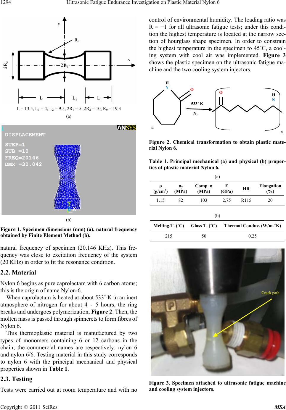 Ultrasonic Fatigue Endurance Investigation on Plastic Material Nylon 6 1294 L = 13.5, L1 = 4, L2 = 9.5, 2R1 = 5, 2R2 = 10, R0 = 19.3 (a) (b) Figure 1. Specimen dimensions (mm) (a), natural frequency obtained by Finite Element Method (b). natural frequency of specimen (20.146 KHz). This fre- quency was close to excitation frequency of the system (20 KHz) in order to fit the resonance condition. 2.2. Material Nylon 6 begins as pure caprolactam with 6 carbon atoms; this is the origin of name Nylon-6. When caprolactam is heated at about 533˚ K in an inert atmosphere of nitrogen for about 4 - 5 hours, the ring breaks and undergoes polymerization, Figure 2. Then, the molten mass is passed through spinnerets to form fibres of Nylon 6. This thermoplastic material is manufactured by two types of monomers containing 6 or 12 carbons in the chain; the commercial names are respectively: nylon 6 and nylon 6/6. Testing material in this study corresponds to nylon 6 with the principal mechanical and physical properties shown in Table 1. 2.3. Testing Tests were carried out at room temperature and with no control of environmental humidity. The loading ratio was R = −1 for all ultrasonic fatigue tests; under this condi- tion the highest temperature is located at the narrow sec- tion of hourglass shape specimen. In order to constrain the highest temperature in the specimen to 45˚C, a cool- ing system with cool air was implemented. Figure 3 shows the plastic specimen on the ultrasonic fatigue ma- chine and the two cooling system injectors. H N H N n O O 533˚K N 2 n Figure 2. Chemical transformation to obtain plastic mate- rial Nylon 6. Table 1. Principal mechanical (a) and physical (b) proper- ties of plastic material Nylon 6. (a) ρ (g/cm3) σy (MPa) Comp. σ (MPa) E (GPa) HR Elongation (%) 1.15 82 103 2.75 R115 20 (b) Melting T. (˚C)Glass T. (˚C) Thermal Conduc. (W/m-˚K) 215 50 0.25 Crack path Figure 3. Specimen attached to ultrasonic fatigue machine and cooling system injectors. Copyright © 2011 SciRes. MSA 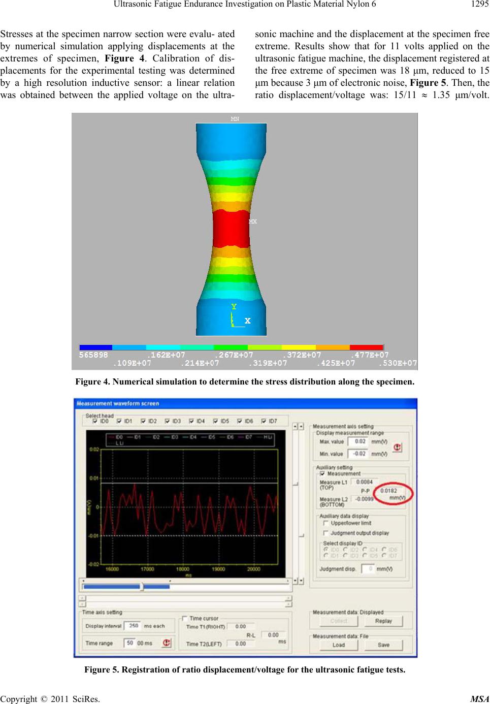 Ultrasonic Fatigue Endurance Investigation on Plastic Material Nylon 6 Copyright © 2011 SciRes. MSA 1295 Stresses at the specimen narrow section were evalu- ated by numerical simulation applying displacements at the extremes of specimen, Figure 4. Calibration of dis- placements for the experimental testing was determined by a high resolution inductive sensor: a linear relation was obtained between the applied voltage on the ultra- sonic machine and the displacement at the specimen free extreme. Results show that for 11 volts applied on the ultrasonic fatigue machine, the displacement registered at the free extreme of specimen was 18 μm, reduced to 15 μm because 3 μm of electronic noise, Figure 5. Then, the ratio displacement/voltage was: 15/11 1.35 μm/volt. Figure 4. Numerical simulation to determine the stress distribution along the specimen. Figure 5. Registration of ratio displacement/voltage for the ultrasonic fatigue tests.  Ultrasonic Fatigue Endurance Investigation on Plastic Material Nylon 6 1296 All tests were loaded between 9.5% and 13% of the ma- terial elastic limit in order to keep the temperature at the narrow section of specimen below 45˚C. 3. Results In Figure 6 are plotted the experimental results obtained on the polymeric material Nylon 6. Vertical axis repre- sents the ratio in percent between the nominal applied stress σn and the yield stress σY of this material. The low values for this ratio (between 9.5% and 13%), corre- sponding to the temperature control at the specimen nar- row section: in increasing the load this temperature in- creases and may surpass the glass transition temperature of the material, inducing high deformation and, in most of the cases, the specimen is carried out of resonance condition. Crack propagation was observed at the narrow section of specimen in a perpendicular plane to the speci- men longitudinal direction; crack origin was not clearly indentified: in some fracture surface it seems to be local- ized inside the specimen, associated with the high tempe- rature at this zone. Crack path at the specimen narrow section Figure 6. Fatigue endurance and crack path for polymeric material Nylon 6. 4. Discussion Ultrasonic fatigue endurance has been obtained for the polymeric material Nylon 6. A critical parameter to carry out experimental tests was the temperature on specimen 9-12; in order to control this parameter three actions were undertaken: 1) the diameter at specimen narrow section was small (5 mm) with aim to reduce the tem- perature gradient at this zone; 2) the applying load was low (9.5% to 13% of material yield stress) in order to limit the heat dissipation associated with the increase on temperature; and 3) cool air was injected at the specimen narrow section. The Figure 7 shows the fracture surface for a specimen tested close to12% of its elastic limit. Some testing specimens present a visible polymeric degradation localized at the crack propagation path, as shown in Figure 8. These specimens were loaded at highest level: close to 12% of elastic limit of material. This should be a limit under the described conditions in order to carry out ul- trasonic fatigue testing without an important thermal ef- fect. Polymeric degradation induced by heat dissipation may hide or overlapping the mechanical fatigue endu- rance of this plastic material. Temperature effect is observed in the Figure 7: at the cooling air sites no important degradation of polymeric chains was observed; then, crack is expected to initiate at the high plastic deformation, associated with the high temperature zones. Ultrasonic fatigue tests were carried out on this polymeric material under temperature control; nevertheless, no internal parameters such as: polymer structure, molecular weight, crosslinking, and filler or diluent type and content 13,14, were analyzed at this stage of work. Cooling air C ooling ai r Figure 7. Fracture surface and cooling air localization for the plastic specimen. Copyright © 2011 SciRes. MSA 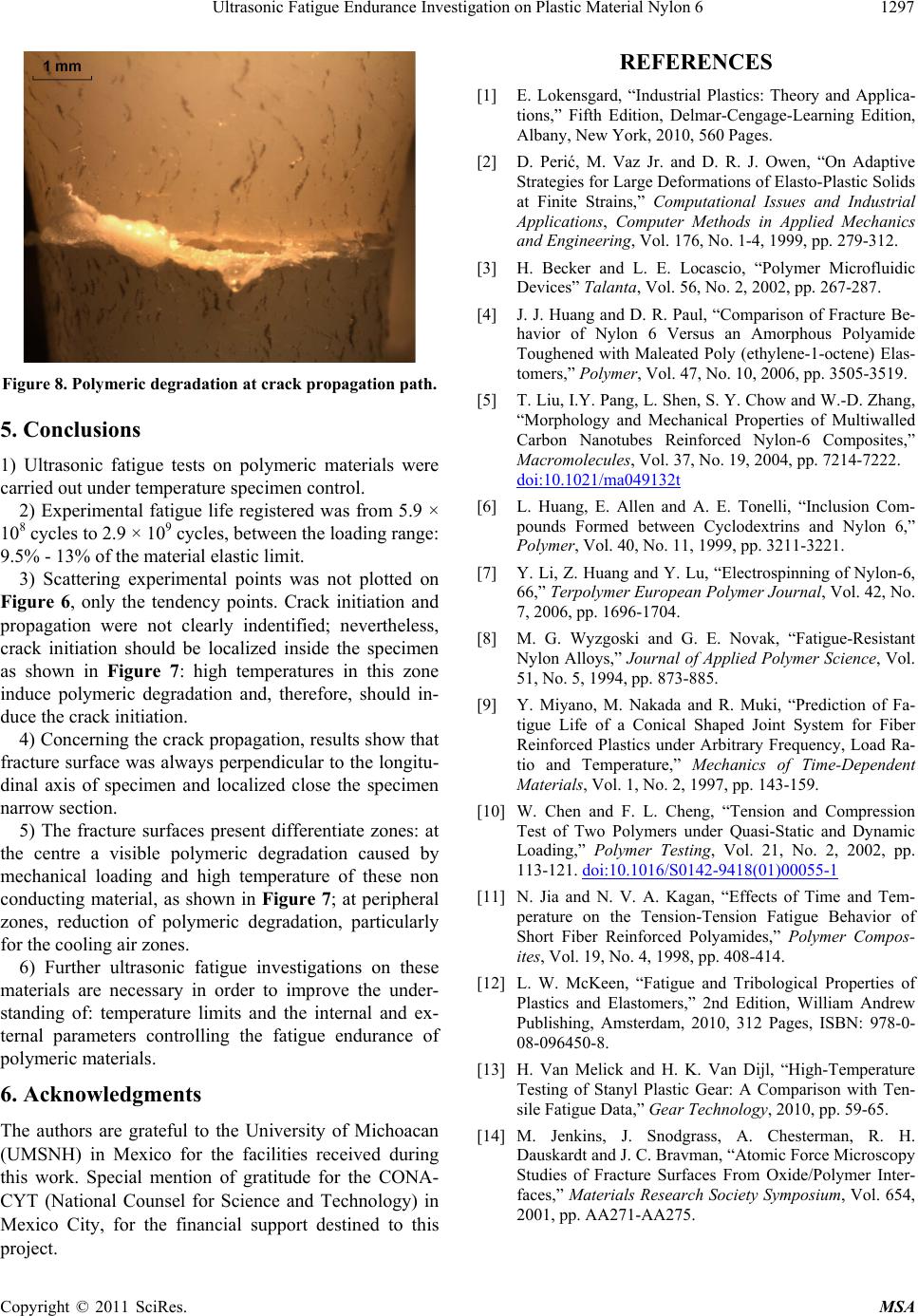 Ultrasonic Fatigue Endurance Investigation on Plastic Material Nylon 61297 Figure 8. Polymeric degradation at crack propagation path. 5. Conclusions 1) Ultrasonic fatigue tests on polymeric materials were carried out under temperature specimen control. 2) Experimental fatigue life registered was from 5.9 × 10⁸ cycles to 2.9 × 10⁹ cycles, between the loading range: 9.5% - 13% of the material elastic limit. 3) Scattering experimental points was not plotted on Figure 6, only the tendency points. Crack initiation and propagation were not clearly indentified; nevertheless, crack initiation should be localized inside the specimen as shown in Figure 7: high temperatures in this zone induce polymeric degradation and, therefore, should in- duce the crack initiation. 4) Concerning the crack propagation, results show that fracture surface was always perpendicular to the longitu- dinal axis of specimen and localized close the specimen narrow section. 5) The fracture surfaces present differentiate zones: at the centre a visible polymeric degradation caused by mechanical loading and high temperature of these non conducting material, as shown in Figure 7; at peripheral zones, reduction of polymeric degradation, particularly for the cooling air zones. 6) Further ultrasonic fatigue investigations on these materials are necessary in order to improve the under- standing of: temperature limits and the internal and ex- ternal parameters controlling the fatigue endurance of polymeric materials. 6. Acknowledgments The authors are grateful to the University of Michoacan (UMSNH) in Mexico for the facilities received during this work. Special mention of gratitude for the CONA- CYT (National Counsel for Science and Technology) in Mexico City, for the financial support destined to this project. REFERENCES [1] E. Lokensgard, “Industrial Plastics: Theory and Applica- tions,” Fifth Edition, Delmar-Cengage-Learning Edition, Albany, New York, 2010, 560 Pages. [2] D. Perić, M. Vaz Jr. and D. R. J. Owen, “On Adaptive Strategies for Large Deformations of Elasto-Plastic Solids at Finite Strains,” Computational Issues and Industrial Applications, Computer Methods in Applied Mechanics and Engineering, Vol. 176, No. 1-4, 1999, pp. 279-312. [3] H. Becker and L. E. Locascio, “Polymer Microfluidic Devices” Talanta, Vol. 56, No. 2, 2002, pp. 267-287. [4] J. J. Huang and D. R. Paul, “Comparison of Fracture Be- havior of Nylon 6 Versus an Amorphous Polyamide Toughened with Maleated Poly (ethylene-1-octene) Elas- tomers,” Polymer, Vol. 47, No. 10, 2006, pp. 3505-3519. [5] T. Liu, I.Y. Pang, L. Shen, S. Y. Chow and W.-D. Zhang, “Morphology and Mechanical Properties of Multiwalled Carbon Nanotubes Reinforced Nylon-6 Composites,” Macromolecules, Vol. 37, No. 19, 2004, pp. 7214-7222. doi:10.1021/ma049132t [6] L. Huang, E. Allen and A. E. Tonelli, “Inclusion Com- pounds Formed between Cyclodextrins and Nylon 6,” Polymer, Vol. 40, No. 11, 1999, pp. 3211-3221. [7] Y. Li, Z. Huang and Y. Lu, “Electrospinning of Nylon-6, 66,” Terpolymer European Polymer Journal, Vol. 42, No. 7, 2006, pp. 1696-1704. [8] M. G. Wyzgoski and G. E. Novak, “Fatigue-Resistant Nylon Alloys,” Journal of Applied Polymer Science, Vol. 51, No. 5, 1994, pp. 873-885. [9] Y. Miyano, M. Nakada and R. Muki, “Prediction of Fa- tigue Life of a Conical Shaped Joint System for Fiber Reinforced Plastics under Arbitrary Frequency, Load Ra- tio and Temperature,” Mechanics of Time-Dependent Materials, Vol. 1, No. 2, 1997, pp. 143-159. [10] W. Chen and F. L. Cheng, “Tension and Compression Test of Two Polymers under Quasi-Static and Dynamic Loading,” Polymer Testing, Vol. 21, No. 2, 2002, pp. 113-121. doi:10.1016/S0142-9418(01)00055-1 [11] N. Jia and N. V. A. Kagan, “Effects of Time and Tem- perature on the Tension-Tension Fatigue Behavior of Short Fiber Reinforced Polyamides,” Polymer Compos- ites, Vol. 19, No. 4, 1998, pp. 408-414. [12] L. W. McKeen, “Fatigue and Tribological Properties of Plastics and Elastomers,” 2nd Edition, William Andrew Publishing, Amsterdam, 2010, 312 Pages, ISBN: 978-0- 08-096450-8. [13] H. Van Melick and H. K. Van Dijl, “High-Temperature Testing of Stanyl Plastic Gear: A Comparison with Ten- sile Fatigue Data,” Gear Technology, 2010, pp. 59-65. [14] M. Jenkins, J. Snodgrass, A. Chesterman, R. H. Dauskardt and J. C. Bravman, “Atomic Force Microscopy Studies of Fracture Surfaces From Oxide/Polymer Inter- faces,” Materials Research Society Symposium, Vol. 654, 2001, pp. AA271-AA275. Copyright © 2011 SciRes. MSA |