

Paper Menu >>
Journal Menu >>
 Journal of Signal and Information Processing, 2011, 2, 227-231 doi:10.4236/jsip.2011.23031 Published Online August 2011 (http://www.SciRP.org/journal/jsip) Copyright © 2011 SciRes. JSIP 227 Optimization of the UWB Radar System in Medical Imaging Taoufik Elmissaoui, Nabila Soudani, Ridha Bouallegue 6’Tel Research Unit Higher School of Communications of Tunis, Sup’Com University of Carthage, Tunis, Tunisia. Email: {elmissaoui.enit, ridha.bouallegue}@gmail.com, [email protected] Received December 18th, 2010; revised May 20th, 2011; accepted May 30th, 2011. ABSTRACT During the last decades, we have witnessed a widespread deployment of the ultra wide band (UWB) radar systems. Considering a medical field, an algorithm optimizing these systems is pointed out in this contribution. Beginning with the description of the UWB radar system, this algorithm has proved to be not only able to take a medical image of the human body but also capable of diverting the human tissue. Moreover, we insist on the fact that this algorithm can easily optimize different radar parameters. So, the human body layer width, the incident angle and the frequency maxi- mizing reflection coefficient are estimated in this paper. Keywords: UWB, Radar, Medical Image, Human Body Model 1. Introduction The ultra wide band (UWB) technology presents many advantages. This technology is used in many fields such as the transmission system and the radar application. In the literature, many studies recommend the deployment the UWB radar in medical imaging [1-4]. In fact, these systems consist of sending ultra short electromagnetic pulses and analyzing the echo reflected by the human body which is exposed to this radiation. Each human body layer makes its proper signature in the reflected signal. Because the human body structure has a variety of composition and electric properties. The UWB radar has several key advantages such as [5]: The pulse has a wide frequency spectrum that can easily cross obstacles, The pulse length is very short but has a very elevated resolution, The short pulse leads to a little energy consumption, It has a good resistance to the multi-path interference, It allows not only the detection of a human being, but also its positioning. In this paper, we introduce an algorithm that optimizes the radar system in the imaging application. In fact, the human body characteristics vary with several parameters like age, sex and organ composition. For this goal, we define our proposed algorithm in the first position. Moreover, we present the different stages of this algo- rithm in the second position. Indeed, our radar system is capable of estimating these parameters automatically in an attempt to optimize the capture of the medical image. For this reason, the UWB radar system starts by com- puting the layer width. After that, she calculates the fre- quency that enables us to maximize the echo strength of each layer. Similarly, we take into consideration the spe- cific absorption rate in order to minimize the effect of the radar radiation. Finally, we discuss the results in the con- clusion. 2. The UWB Radar System for a Medical Application The UWB radar is a system that uses an ultra wide elec- tromagnetic pulse. The band of this device must be greater than 25% [6]. The purpose of our system is to capture the human body layer image. This system en- ables doctors to diagnose the human body structure. In- deed, it can also be used in cancer detection because it presents electric properties different form the normal human tissue. Similarly, UWB radar enables doctors to control the human heart movement because the human dilated tissue has electric properties different from the non dilated tissue. The bases of our radar system is sending an electro- magnetic pulse and exploiting the several echoes re- flected by each human body structure. Figure 1 presents the radar system architecture that is 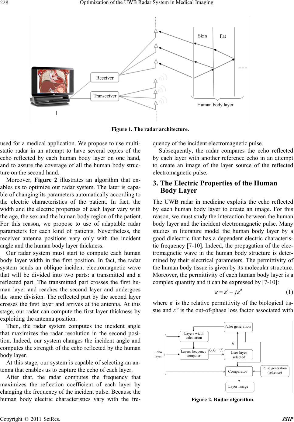 Optimization of the UWB Radar System in Medical Imaging 228 Receiver Tr ansce iv er Human body layer Skin Fat Figure 1. The radar architecture. used for a medical application. We propose to use multi- static radar in an attempt to have several copies of the echo reflected by each human body layer on one hand, and to assure the coverage of all the human body struc- ture on the second hand. Moreover, Figure 2 illustrates an algorithm that en- ables us to optimize our radar system. The later is capa- ble of changing its parameters automatically according to the electric characteristics of the patient. In fact, the width and the electric properties of each layer vary with the age, the sex and the human body region of the patient. For this reason, we propose to use of adaptable radar parameters for each kind of patients. Nevertheless, the receiver antenna positions vary only with the incident angle and the human body layer thickness. Our radar system must start to compute each human body layer width in the first position. In fact, the radar system sends an oblique incident electromagnetic wave that will be divided into two parts: a transmitted and a reflected part. The transmitted part crosses the first hu- man layer and reaches the second layer and undergoes the same division. The reflected part by the second layer crosses the first layer and arrives at the antenna. At this stage, our radar can compute the first layer thickness by exploiting the antenna position. Then, the radar system computes the incident angle that maximizes the radar resolution in the second posi- tion. Indeed, our system changes the incident angle and computes the strength of the echo reflected by the human body layer. At this stage, our system is capable of selecting an an- tenna that enables us to capture the echo of each layer. After that, the radar computes the frequency that maximizes the reflection coefficient of each layer by changing the frequency of the incident pulse. Because the human body electric characteristics vary with the fre- quency of the incident electromagnetic pulse. Subsequently, the radar compares the echo reflected by each layer with another reference echo in an attempt to create an image of the layer source of the reflected electromagnetic pulse. 3. The Electric Properties of the Human Body Layer The UWB radar in medicine exploits the echo reflected by each human body layer to create an image. For this reason, we must study the interaction between the human body layer and the incident electromagnetic pulse. Many studies in literature model the human body layer by a good dielectric that has a dependent electric characteris- tic frequency [7-10]. Indeed, the propagation of the elec- tromagnetic wave in the human body structure is deter- mined by their electrical parameters. The permittivity of the human body tissue is given by its molecular structure. Moreover, the permittivity of each human body layer is a complex quantity and it can be expressed by [7-10]: j (1) where ε′ is the relative permittivity of the biological tis- sue and ε" is the out-of-phase loss factor associated with Pulse generation Comparator Layer Image User layer selected Layers frequency computer Layers width calculation Pulse generation (refrence) Echo layer f 1 12 ,, n f ff Figure 2. Radar algorithm. Copyright © 2011 SciRes. JSIP  Optimization of the UWB Radar System in Medical Imaging229 it. As such: 0 (2) As before, the skin depth of the electromagnetic pulse in each human body layer can be written as follows [11]: 1 2 2 00 0 11 2 r r 1 (3) where: : the wave angular frequency 0 : the free space permittivity. 0 : the free space electromagnetic permeability. : the relative conductivity. r : the relative permittivity. The conductivity of the human body layer tissue has different values depending on their compositions and physiological functions. Figure 3 shows the human body us the biological structure used in this paper. 4. Thickness Estimate of Each Layer The first step of our radar system is the computing each layer width. For this purpose, we use an electromagnetic pulse with an oblique incident. According to [2], we can estimate the antenna position that enables us to capture the echo of each human body layer. In our case, we place many receiver antennas that en- able us to capture each echo reflected by the human structure. In fact, the nearest layer of the transmission antenna has the antenna position closest to the trans- ceiver antenna. Let us start by the first layer in a free space. In this section, we presume a transmitter antenna placed in a position P that radiates electromagnetic with an incident angle in equal to 45˚. We start by computing the dis- tance that separates the radar antenna transmitter and the skin layer. In fact, the distance can be expressed as: 1 02tan in P (4) where, P1 is the antenna position that captures the echo reflected by layer 1. Moreover, the skin width can be expressed as: Figure 3. Layered at a tissue model. 21 ,1 2tan SKin t Pl (5) Here, P2 is the antenna position that captures the echo reflected by layer 2. Similarly, the thickness of the muscle layer can be written as: 312 ,2 2tan Muscl e t Pll (6) Here, P3 is the antenna position that captures the echo reflected by layer 3. At this stage, we can generalize this result. The width of each layer that composes the human body structure can be formulated as: 12 1 ,1 2tan th ii i ti ll l P (7) where, Pi is the antenna position that captures the echo reflected by the layer. th i This finding enables us to compute the travel echo of each human layer. In addition with [2] the travel time for the layer can be expressed as: th i 1 1 1 ii i i i dd ttv (8) Here, di is the distance crossed by the ith echo layer and presented by: 1 ,1 2sin i ii ti l dd (9) When we examine the result given by the last equation, we conclude that it is possible to distinguish the echo layer by its arrival time to the receiver. 5. The Frequency of Each Layer Our radar system exploits the echo reflected by the hu- man body structure. On this basis, we must optimize the reflection coefficient of each human body layer. In this section, we try to set the frequency that enables our sys- tem to maximize the power of the signal reflected by the human body structure. The reflection of each layer is dealt with [1], we out- line briefly the results in this section. Indeed, this value is presented by: 232 31 1 t ii i TTTTTT i (10) where, i and i T present respectively the total field transmission and the reflection by the ith layer for an in- cident wave on the left side. They can be expressed as: 1,, 1 1,, 1 (1)(1) exp(2) 1exp(2) i ii iii i i iiii i rr Trr (11) Copyright © 2011 SciRes. JSIP  Optimization of the UWB Radar System in Medical Imaging 230 1,, 1 1,, 1 exp 2 1exp2 i ii iii i i ii iii rr rr (12) i, is the reflection coefficient of the i layer of a com- ing pulse from the right. T 1,, 1 1,, 1 (1)(1) exp2 1exp2 i ii iii i i iiii i rr Trr (13) ,1ii r, is the coefficient between two successive layers. 1 ,1 1 ii ii ii Z Z r Z Z (14) Zi represents the i layer impedance 0 , i ri Z Z (15) where, Z0 is the impedance of the free space. 6. The Specific Absorption Rate The electromagnetic wave is able to penetrate in a bio- logical structure. The interaction between the human body layer and the incident pulse result in a complex distribution of the local fields. This interaction is related to the dielectric properties of the human layer and the wave frequency. The distribution of the electromagnetic wave in the human body is known by SAR (Specific Absorption Rate). SAR can be expressed by [12]: 2 SAR E (16) where, is the conductivity of the tissue in Siemens/ Meter is the mass density in kg/m3 and E is the strength of the electric field in volts/meter. Our goal in this section is to minimize SAR value of each layer that composes the human body. According to Figure 4, the SAR decreases according to the frequency of the incident pulse. The maximum SAR was, in all the cases, located in the muscle and lung layer. The density of each layer is indicated in the Table 1. 7. The Thickness Measurement of Each Human Body Layer To illustrate the given results in this section, we will try to compute the human body section. In fact, we used multi-static radar that sends an electromagnetic pulse with an oblique incident. This signal reaches the human body layer and comes to the radar antennas. Each echo layer has its own way, direction and an antenna receiver. Finally, each layer triggers its own antenna. For this rea- son, we consider the excited antenna positions and we compute the thickness of that layer sources of the echo Figure 4. The SAR of each human body layer versus fre- quency. Table 1. Density ρ in kg/m3 of the body tissues [13]. Layer ρ in Kg/m3 Skin 1100 Fat 1100 Muscle 1041 Bone 1990 Lung 655 Table 2. Estimated antenna position and the measured thickness of each echo layer. Layer Skin FAT Muscle Bone Lung Estimated antenna position (mm) 100 100.3572 108.3314 111.1587113.6691 Permittivity (S/m) 35.7745.0291 49.54 16.05 44.859 Measured thickness (mm)1.5 12 14 7 6 reflected. The permittivity of each layer used in this sec- tion, is measured by Gabriel at a frequency equal to 5 GHz. The results are summed up in the Table 2. 8. Conclusions The UWB and radar systems have several advantages. This encourages us to use these inventions in several fields including medical applications. To enhance these advantages we propose to use the UWB radar systems in the medical imaging field. In fact, we put the emphasis on this manuscript on an algorithm that optimizes our radar system. This technique makes the radar system capable of adapting its parameters depending on the Copyright © 2011 SciRes. JSIP  Optimization of the UWB Radar System in Medical Imaging Copyright © 2011 SciRes. JSIP 231 characteristics of the tissue of the patient. Furthermore, our UWB radar system estimates the width of each layer and computes the frequency enabling us to maximize the echo reflected by the human body as exposed in the radar radiation. For example we deploy a frequency 5 GHz and 6 GHz respectively in an attempt to detect the echo reflected by the skin and muscle layer. REFERENCES [1] E. Taoufik, S. Nabila and B. Ridha, “The Reflection of Electromagnetic Field by Body Tissue in the UWB Fre- quency Range,” IEEE International Radar Conference, Mai, 2010, pp. 1403-1407. [2] E. Taoufik, S. Nabila and B. Ridha, “New Radar System in Medicine,” The 2010 European Signal Processing Con- ference (EUSIPCO-2010), Aalborg, 23-27 August 2010. [3] G. Varotto and E. M. Staderini, “A 2D Simple Attenuation Model for EM Waves in Human Tissues: Comparison with a FDTD 3D Simulator for UWB Medical Radar,” 2008 IEEE International Conference on Ultra-Widebanb (ICUWB2008), Hannover, 10-12 September 2008, pp. 1- 4. [4] E. M. Staderini, “UWB Radars in Medicine,” IEEE Aerospace and Electronic Systems Magazine, Vol. 17, No. 1, January 2002, pp. 13-18. doi:10.1109/62.978359 [5] A. G. Yarovoy, L. P. Ligthart, J. Matuzas and B. Levitas, “UWB Radar for Human Being Detection,” IEEE Aero- space and Electronic Systems Magazine, Vol. 21, No. 3, March 2006, pp. 10-14. doi:10.1109/MAES.2006.1624185 [6] Y. P. Zhang and Q. Li, “Performance of UWB Impulse Radio with Planar Monopoles Over On-Human-Body Propagation Channel for Wireless Body Area Networks,” IEEE Transaction on Antennas and Propagation, Vol. 55, No. 10, October 2007, pp. 2907-2914. doi:10.1109/TAP.2007.905825 [7] C. Gabriel, “A Compilation of the Dielectric Properties of Body Tissues at RF and Microwave Frequencies,” Ra- diofrequency Radiation Division, Brooks AFB, San An- tonio, TX, Contract AL/OE-TR-1996-0037, 1996. [8] C. Gabriel, S. Gabriel and E. Corthout, “The Dielectric Properties of Biological Tissues: I. Literature Survey,” Physics in Medicine and Biology, Vol. 41, No. 11, No- vember 1996, pp. 2231-2249. [9] S. Gabriel, R. W. Lau and C. Gabriel, “The Dielectric Properties of Biological Tissues: II. Measurements on the Frequency Range 10 Hz to 20 GHz,” Physics in Medicine and Biology, Vol. 41, No. 11, November 1996, pp. 2251- 2269. doi:10.1088/0031-9155/41/11/002 [10] S. Gabriel, R. W. Lau and C. Gabriel, “The Dielectric Properties of Biological Tissues: III. Parametric Models for the Dielectric Spectrum of Tissues,” Physics in Medi- cine and Biology, Vol. 41, No. 11, November 1996, pp. 2271-2293. doi:10.1088/0031-9155/41/11/003 [11] G. Kang and O. P. Gandh, “Effect of Dielectric Properties on the Peak 1- and 10-g SAR for 802.11 a/b/g Frequencies 2.45 and 5.15 to 5.85 GHz,” IEEE Transactions on Elec- tromagnetic Compatibility, Vol. 46, No. 2, May 2004, pp. 268-274. doi:10.1109/TEMC.2004.826875 [12] E. R. Adair and R. C. Petersen, “Biological Effects of Radio-Frequency/Microwave Radiation,” IEEE Transac- tions on Microwave Theory and Techniques, Vol. 50, No. 3, March 2002, pp. 953-962. doi:10.1109/22.989978 [13] A. Christ, A. Klingenböck, T. Samaras, C. Goiceanu and N. Kuster, “The Dependence of Electromagnetic Far-Field Absorption on Body Tissue Composition in the Frequency Range From 300 MHz to 6 GHz,” IEEE Transactions on Microwave Theory and Techniques, Vol. 54, No. 5, May 2006, pp. 2188-2195. doi:10.1109/TMTT.2006.872789 |