

Paper Menu >>
Journal Menu >>
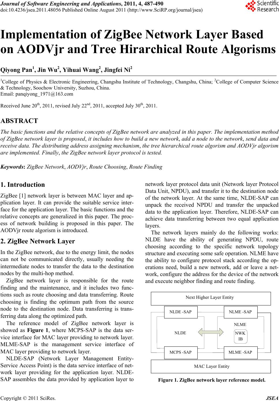 Journal of Software Engineering and Applications, 2011, 4, 487-490 doi:10.4236/jsea.2011.48056 Published Online August 2011 (http://www.SciRP.org/journal/jsea) Copyright © 2011 SciRes. JSEA 487 Implementation of ZigBee Network Layer Based on AODVjr and Tree Hirarchical Route Algorisms Qiyong Pan1, Jin Wu2, Yihuai Wang2, Jingfei Ni2 1College of Physics & Electronic Engineering, Changshu Institute of Technology, Changshu, China; 2College of Computer Science & Technology, Soochow University, Suzhou, China. Email: [email protected] Received June 20th, 2011, revised July 22nd, 2011, accepted July 30th, 2011. ABSTRACT The basic functions and the relative concepts of ZigBee network are analyzed in this paper. The implementation method of ZigBee network layer is proposed, it includes how to build a new network, add a node to th e network, send data and receive data. The distributing address assigning mechanism, the tree hierarchical route algorism and AODVjr algorism are implemented. Finally, the ZigBee network layer protocol is tested. Keywords: ZigBee Network, AODVjr, Route Choosing, Route Finding 1. Introduction ZigBee [1] network layer is between MAC layer and ap- plication layer. It can provide the suitable service inter- face for the application layer. The basic functions and the relative concepts are generalized in this paper. The proc- ess of network building is proposed in this paper. The AODVjr route algorism is introduced. 2. ZigBee Network Layer In the ZigBee network, due to the energy limit, the nodes can not be communicated directly, usually needing the intermediate nodes to transfer the data to the destination nodes by the multi-hop method. ZigBee network layer is responsible for the route finding and the maintenance, and it includes two func- tions such as route choosing and data transferring. Route choosing is finding the optimum path from the source node to the destination node. Data transferring is trans- ferring data along the optimized path. The reference model of ZigBee network layer is showed as Figure 1, where MCPS-SAP is the data ser- vice interface for MAC layer providing to network layer. MLME-SAP is the management service interface of MAC layer providing to network layer. NLDE-SAP (Network Layer Management Entity- Service Access Point) is the data service interface of net- work layer providing for the application layer. NLDE- SAP assembles the data provided by application layer to network layer protocol data unit (Network layer Protocol Data Unit, NPDU), and transfer it to the destination node of the network layer. At the same time, NLDE-SAP can unpack the received NPDU and transfer the unpacked data to the application layer. Therefore, NLDE-SAP can achieve data transferring between two equal application layers. The network layers mainly do the following works: NLDE have the ability of generating NPDU, route choosing according to the specific network topology structure and executing some safe operation. NLME have the ability to configure protocol stack according the op- erations need, build a new network, add or leave a net- work, configure the address for the device of the network and execute neighbor finding and route finding. N ext Higher Layer Entity N LDE -SAP N LME -SAP MCPS -SAP MLME - SAP MAC Layer Entity N W K IB N LDE N LME Figure 1. ZigBee network layer reference model. 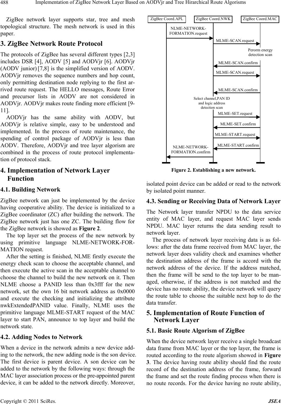 Implementation of ZigBee Network Layer Based on AODVjr and Tree Hirarchical Route Algorisms 488 ZigBee network layer supports star, tree and mesh topological structure. The mesh network is used in this paper. 3. ZigBee Network Route Protocol The protocols of ZigBee has several different types [2,3] includes DSR [4], AODV [5] and AODVjr [6]. AODVjr (AODV junior) [7,8] is the simplified version of AODV. AODVjr removes the sequence numbers and hop count, only permitting destination node replying to the first ar- rived route request. The HELLO messages, Route Error and precursor lists in AODV are not considered in AODVjr. AODVjr make s rou te f indin g more efficien t [9- 11]. AODVjr has the same ability with AODV, but AODVjr is relative simple, easy to be understood and implemented. In the process of route maintenance, the spending of control package of AODVjr is less than AODV. Therefore, AODVjr and tree layer algorism are combined in the process of route protocol implementa- tion of protocol stack. 4. Implementation of Network Layer Function 4.1. Building Network ZigBee network can just be implemented by the device having cooperative ability. The device is initialized to a ZigBee coordinator (ZC) after building the network. The ZigBee network just has one ZC. The building flow for the ZigBee network is sh owed as Figure 2. The top layer set the process of the new network by using primitive language NLME-NETWORK-FOR- MATION request. After the setting is finished, NLME firstly execute the energy check scan to choose the acceptable channel, and then execute the active scan in the acceptable channel to choose the channel to build the new network on it. Then NLME choose a PANID less than 0x3fff for the new network, set the own 16 bit network address as 0x0000 and execute the checking and initializing the attribute nwkExtendedPANID value. Finally, NLME uses the primitive language MLME-START request of the MAC layer to start PAN, announce to top layer and build the network state. 4.2. Adding Nodes to Network When a device in the network admits a new device add- ing to the network, the new adding node is the son device. The first device is parent device. A son device can be added to the network by the following ways: throug h the MAC layer association process or t he pre-appoi nt ed parent device, it can be added to the network directly. Moreover , NLME-NETWORK- FORMATION.confirm MLME-SET.confirm MLME-SCAN.request MLME-START.request MLME-START.confirm MLME-SCAN.request MLME-SCAN.confirm MLME-SCAN.confirm NLME-NETWORK- FORMATION.request ZigBee Coord.APLZigBee Coord.NWK ZigBee Coord.MAC MLME-SET.request Select channel,PAN ID and logic address detection scan Perorm energy detection scan Figure 2. Establishing a new netw or k. isolated point device can be added or read to the network by isolated point manner. 4.3. Sending or Receiving Data of Network Layer The Network layer transfer NPDU to the data service entity of MAC layer, and request MAC layer sends NPDU. MAC layer returns the data sending result to network layer. The process of network layer receiving data is as fol- lows: after the data frame received from MAC layer, the network layer does validity check and examines whether the destination address of the frame is accord with the network address of the device. If the address matched, then the frame will be send to the top layer to be man- aged, otherwise, if the address is not matched and the device has no rou te ability, the device ne twork will query the route table to choose the suitable next hop to do the data transfer. 5. Implementation of Route Function of Network Layer 5.1. Basic Route Algorism of ZigBee When the device network layer receive a single broadcast data frame from MAC layer or the top layer, the frame is routed according to the route algorism showed in Figure 3. The device having route ability should find the route record of the destination address of the frame, forward the frame and set the route finding process when there is no route records. For the device having no route ability, Copyright © 2011 SciRes. JSEA 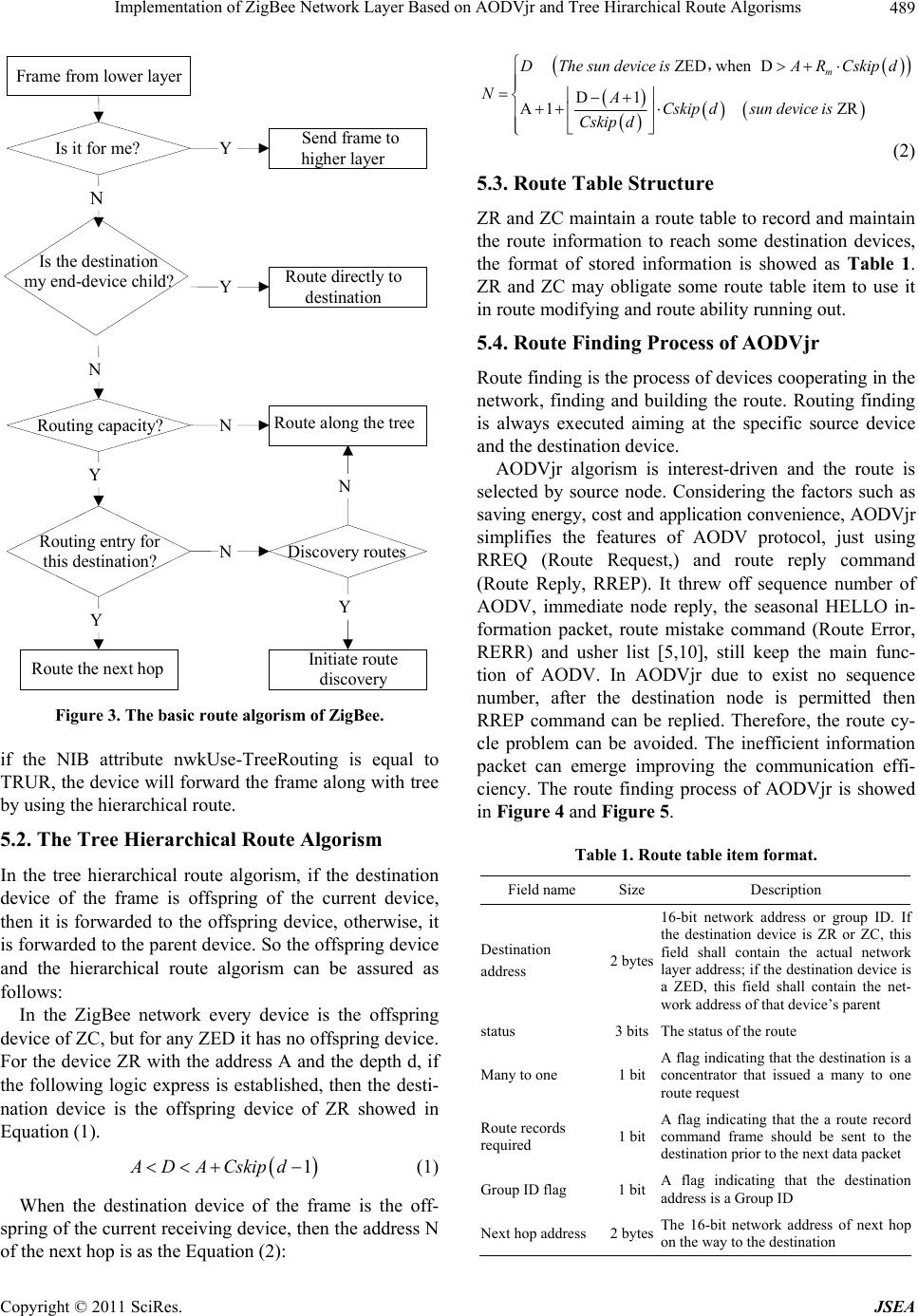 Implementation of ZigBee Network Layer Based on AODVjr and Tree Hirarchical Route Algorisms489 Is i t for m e? Send frame to higher layer Y N Frame from lower laye r Is the destination my end-device child? Route directl y to destination Y N Routing capacity? Route along the tree N Y Routing entry fo r thi s destination? Y Route the next hop Dis covery routes N Y Initi ate rout e discovery N Figure 3. The basic route algorism of ZigBee. if the NIB attribute nwkUse-TreeRouting is equal to TRUR, the device will forward the frame along with tree by using the hierarchical route. 5.2. The Tree Hierarchical Route Algorism In the tree hierarchical route algorism, if the destination device of the frame is offspring of the current device, then it is forwarded to the offspring device, otherwise, it is forwarded to the parent device. So the offspring device and the hierarchical route algorism can be assured as follows: In the ZigBee network every device is the offspring device of ZC, but for any ZED it has no offspring device. For the device ZR with the address A and the depth d, if the following logic express is established, then the desti- nation device is the offspring device of ZR showed in Equation (1). 1ADACskipd (1) When the destination device of the frame is the off- spring of the current receiving device, then the address N of the next hop is as the Equation (2): ZEDwhenD D1 A1 ZR m D Thesun device isARCskipd NACskipdsundevice is Cskip d , (2) 5.3. Route Table Structure ZR and ZC maintain a route table to record and maintain the route information to reach some destination devices, the format of stored information is showed as Table 1. ZR and ZC may obligate some route table item to use it in route modifying an d route ability running out. 5.4. Route Finding Process of AODVjr Route finding is the pr ocess of d evices cooperating in the network, finding and building the route. Routing finding is always executed aiming at the specific source device and the destination device . AODVjr algorism is interest-driven and the route is selected by source node. Considering the factors such as saving energy, cost and application convenience, AODVjr simplifies the features of AODV protocol, just using RREQ (Route Request,) and route reply command (Route Reply, RREP). It threw off sequence number of AODV, immediate node reply, the seasonal HELLO in- formation packet, route mistake command (Route Error, RERR) and usher list [5,10], still keep the main func- tion of AODV. In AODVjr due to exist no sequence number, after the destination node is permitted then RREP command can be replied. Therefore, the route cy- cle problem can be avoided. The inefficient information packet can emerge improving the communication effi- ciency. The route finding process of AODVjr is showed in Figure 4 and Figure 5. Table 1. Route table item format. Field name Size Description Destination address 2 bytes 16-bit network address or group ID. I f the destination device is ZR or ZC, this field shall contain the actual networ k layer address; if the destination device is a ZED, this field shall contain the net- work address of that device’s parent status 3 bitsThe status of the route Many to one 1 bit A flag indicating that the destination is a concentrator that issued a many to one route request Route records required 1 bit A flag indicating that the a route record command frame should be sent to the destination prior to the next da t a p a cket Group ID flag 1 bit A flag indicating that the destination address is a Group ID Next hop address 2 bytesThe 16- b it network address of next hop on the way to the destination Copyright © 2011 SciRes. JSEA 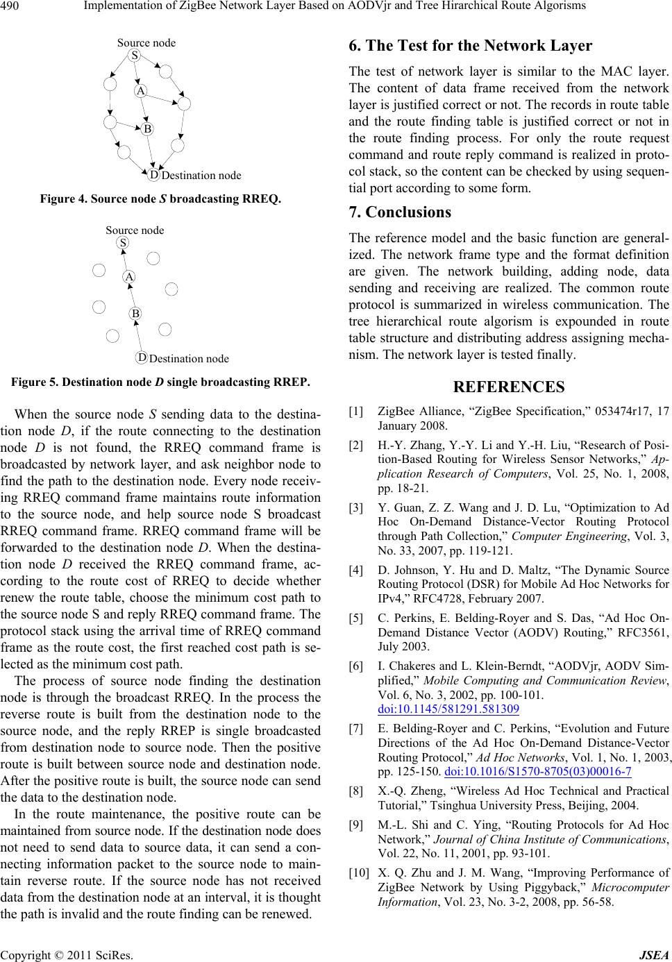 Implementation of ZigBee Network Layer Based on AODVjr and Tree Hirarchical Route Algorisms Copyright © 2011 SciRes. JSEA 490 S A B D Sou rce node Destination node 6. The Test for the Network Layer The test of network layer is similar to the MAC layer. The content of data frame received from the network layer is justified correct or not. Th e record s in rou te table and the route finding table is justified correct or not in the route finding process. For only the route request command and route reply command is realized in proto- col stack, so the content can be checked by using sequen- tial port according to some form. Figure 4. Source node S broadcasting RREQ. 7. Conclusions S A B D Source node Destina ti on node The reference model and the basic function are general- ized. The network frame type and the format definition are given. The network building, adding node, data sending and receiving are realized. The common route protocol is summarized in wireless communication. The tree hierarchical route algorism is expounded in route table structure and distributing address assigning mecha- nism. The network layer is tested finally. Figure 5. Destination node D single broadcasting RREP. REFERENCES [1] ZigBee Alliance, “ZigBee Specification,” 053474r17, 17 January 2008. When the source node S sending data to the destina- tion node D, if the route connecting to the destination node D is not found, the RREQ command frame is broadcasted by network layer, and ask neighbor node to find the path to the destination node. Every node receiv- ing RREQ command frame maintains route information to the source node, and help source node S broadcast RREQ command frame. RREQ command frame will be forwarded to the destination node D. When the destina- tion node D received the RREQ command frame, ac- cording to the route cost of RREQ to decide whether renew the route table, choose the minimum cost path to the source node S and r eply RREQ command frame. The protocol stack using the arrival time of RREQ command frame as the route cost, the first reached cost path is se- lected as the minimum cost path. [2] H.-Y. Zhang, Y.-Y. Li and Y.-H. Liu, “Research of Posi- tion-Based Routing for Wireless Sensor Networks,” Ap- plication Research of Computers, Vol. 25, No. 1, 2008, pp. 18-21. [3] Y. Guan, Z. Z. Wang and J. D. Lu, “Optimization to Ad Hoc On-Demand Distance-Vector Routing Protocol through Path Collection,” Computer Engineering, Vol. 3, No. 33, 2007, pp. 119-121. [4] D. Johnson, Y. Hu and D. Maltz, “The Dynamic Source Routing Protocol (DSR) for Mobile Ad Hoc Networks for IPv4,” RFC4728, February 2007. [5] C. Perkins, E. Belding-Royer and S. Das, “Ad Hoc On- Demand Distance Vector (AODV) Routing,” RFC3561, July 2003. [6] I. Chakeres and L. Klein-Berndt, “AODVjr, AODV Sim- plified,” Mobile Computing and Communication Review, Vol. 6, No. 3, 2002, pp. 100-101. doi:10.1145/581291.581309 The process of source node finding the destination node is through the broadcast RREQ. In the process the reverse route is built from the destination node to the source node, and the reply RREP is single broadcasted from destination node to source node. Then the positive route is built between source node and destination node. After the positive route is built, the sour ce node can send the data to the destination node. [7] E. Belding-Royer and C. Perkins, “Evolution and Future Directions of the Ad Hoc On-Demand Distance-Vector Routing Protocol,” Ad Hoc Networks, Vol. 1, No. 1, 2003, pp. 125-150. doi:10.1016/S1570-8705(03)00016-7 [8] X.-Q. Zheng, “Wireless Ad Hoc Technical and Practical Tutorial,” Tsinghua University Press, Beijing, 2004. In the route maintenance, the positive route can be maintained from source node. If the destination node does not need to send data to source data, it can send a con- necting information packet to the source node to main- tain reverse route. If the source node has not received data from the destination node at an interval, it is thought the path is invalid and the route finding can be renewed. [9] M.-L. Shi and C. Ying, “Routing Protocols for Ad Hoc Network,” Journal of China Institute of Communications, Vol. 22, No. 11, 2001, pp. 93-101. [10] X. Q. Zhu and J. M. Wang, “Improving Performance of ZigBee Network by Using Piggyback,” Microcomputer Information, Vol. 23, No. 3-2, 2008, pp. 56-58. |