

Paper Menu >>
Journal Menu >>
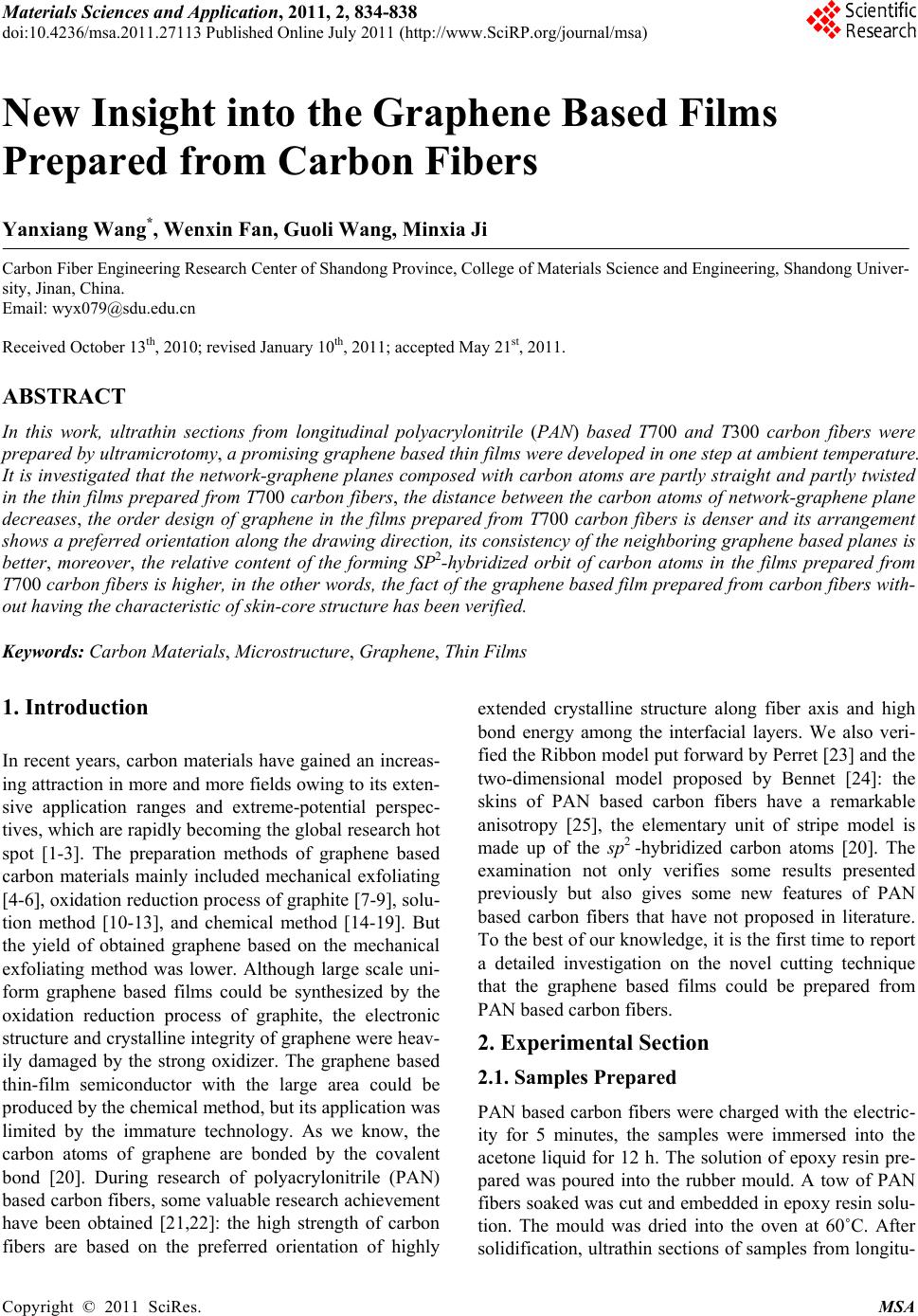 Materials Sciences and Applicatio n, 2011, 2, 834-838 doi:10.4236/msa.2011.27113 Published Online July 2011 (http://www.SciRP.org/journal/msa) Copyright © 2011 SciRes. MSA New Insight into the Graphene Based Films Prepared from Carbon Fibers Yanxiang Wang*, Wenxin Fan, Guoli Wang, Minxia Ji Carbon Fiber Engineering Research Center of Shandong Province, College of Materials Science and Engineering, Shandong Univer- sity, Jinan, China. Email: [email protected] Received October 13th, 2010; revised January 10th, 2011; accepted May 21st, 2011. ABSTRACT In this work, ultrathin sections from longitudinal polyacrylonitrile (PAN) based T700 and T300 carbon fibers were prepared by ultramicrotomy, a promising graphene based thin films were developed in one step at ambient temperature. It is investigated that the network-graphene planes composed with carbon atoms are partly straight and partly twisted in the thin films p repared from T700 carbon fibers, the distance between the carbon atoms of network-graphene plane decreases, the order design of graphene in the films prepared from T700 carbon fibers is denser and its arrangement shows a preferred orientation along the drawing direction, its consistency of the neighboring graphene based planes is better, moreover, the relative content of the forming SP2-hybridized orbit of carbon atoms in the films prepared from T700 carbon fibers is higher, in the other words, the fa ct of the graphene based film prepared from carb on fibers with- out having the characteristic of skin-core structu re has been verified. Keywords: Carbon Ma terials, Microstructure, Graphene, Thin Films 1. Introduction In recent years, carbon materials have gained an increas- ing attraction in more and more fields owing to its exten- sive application ranges and extreme-potential perspec- tives, which are rapidly becoming the global research hot spot [1-3]. The preparation methods of graphene based carbon materials mainly included mechanical exfoliating [4-6], oxidation reduction process of graphite [7-9], solu- tion method [10-13], and chemical method [14-19]. But the yield of obtained graphene based on the mechanical exfoliating method was lower. Although large scale uni- form graphene based films could be synthesized by the oxidation reduction process of graphite, the electronic structure and crystalline integrity of graphene were heav- ily damaged by the strong oxidizer. The graphene based thin-film semiconductor with the large area could be produced by the chemical method, but its application was limited by the immature technology. As we know, the carbon atoms of graphene are bonded by the covalent bond [20]. During research of polyacrylonitrile (PAN) based carbon fibers, some valuable research achievement have been obtained [21,22]: the high strength of carbon fibers are based on the preferred orientation of highly extended crystalline structure along fiber axis and high bond energy among the interfacial layers. We also veri- fied the Ribbon model put forward by Perret [23] and the two-dimensional model proposed by Bennet [24]: the skins of PAN based carbon fibers have a remarkable anisotropy [25], the elementary unit of stripe model is made up of the sp2 -hybridized carbon atoms [20]. The examination not only verifies some results presented previously but also gives some new features of PAN based carbon fibers that have not proposed in literature. To the best of our knowledge, it is the first time to report a detailed investigation on the novel cutting technique that the graphene based films could be prepared from PAN based carbon fibers. 2. Experimental Section 2.1. Samples Prepared PAN based carbon fibers were charged with the electric- ity for 5 minutes, the samples were immersed into the acetone liquid for 12 h. The solution of epoxy resin pre- pared was poured into the rubber mould. A tow of PAN fibers soaked was cut and embedded in epoxy resin solu- tion. The mould was dried into the oven at 60˚C. After solidification, ultrathin sections of samples from longitu- 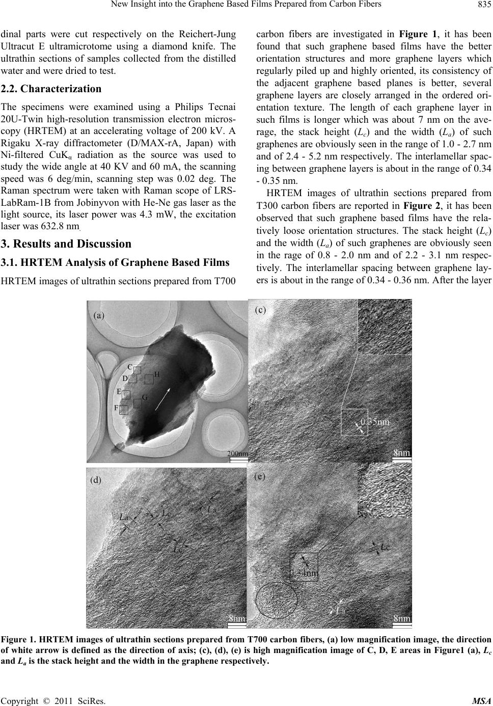 New Insight into the Graphene Based Films Prepared from Carbon Fibers835 dinal parts were cut respectively on the Reichert-Jung Ultracut E ultramicrotome using a diamond knife. The ultrathin sections of samples collected from the distilled water and were dried to test. 2.2. Characterization The specimens were examined using a Philips Tecnai 20U-Twin high-resolution transmission electron micros- copy (HRTEM) at an accelerating voltage of 200 kV. A Rigaku X-ray diffractometer (D/MAX-rA, Japan) with Ni-filtered CuKα radiation as the source was used to study the wide angle at 40 KV and 60 mA, the scanning speed was 6 deg/min, scanning step was 0.02 deg. The Raman spectrum were taken with Raman scope of LRS- LabRam-1B from Jobinyvon with He-Ne gas laser as the light source, its laser power was 4.3 mW, the excitation laser was 632.8 nm. 3. Results and Discussion 3.1. HRTEM Analysis of Graphene Based Films HRTEM images of ultrathin sections prepared from T700 carbon fibers are investigated in Figure 1, it has been found that such graphene based films have the better orientation structures and more graphene layers which regularly piled up and highly oriented, its consistency of the adjacent graphene based planes is better, several graphene layers are closely arranged in the ordered ori- entation texture. The length of each graphene layer in such films is longer which was about 7 nm on the ave- rage, the stack height (Lc) and the width (La) of such graphenes are obviously seen in the range of 1.0 - 2.7 nm and of 2.4 - 5.2 nm respectively. The interlamellar spac- ing between graphene layers is about in the range of 0.34 - 0.35 nm. HRTEM images of ultrathin sections prepared from T300 carbon fibers are reported in Figure 2, it has been observed that such graphene based films have the rela- tively loose orientation structures. The stack height (Lc) and the width (La) of such graphenes are obviously seen in the rage of 0.8 - 2.0 nm and of 2.2 - 3.1 nm respec- tively. The interlamellar spacing between graphene lay- ers is about in the range of 0.34 - 0.36 nm. After the layer Figure 1. HRTEM images of ultrathin sections prepared from T700 carbon fibers, (a) low magnification image, the direction of white arrow is defined as the direction of axis; (c), (d), (e) is high magnification image of C, D, E areas in Figure1 (a), Lc and La is the stack height and the width in the graphene respectively . Copyright © 2011 SciRes. MSA 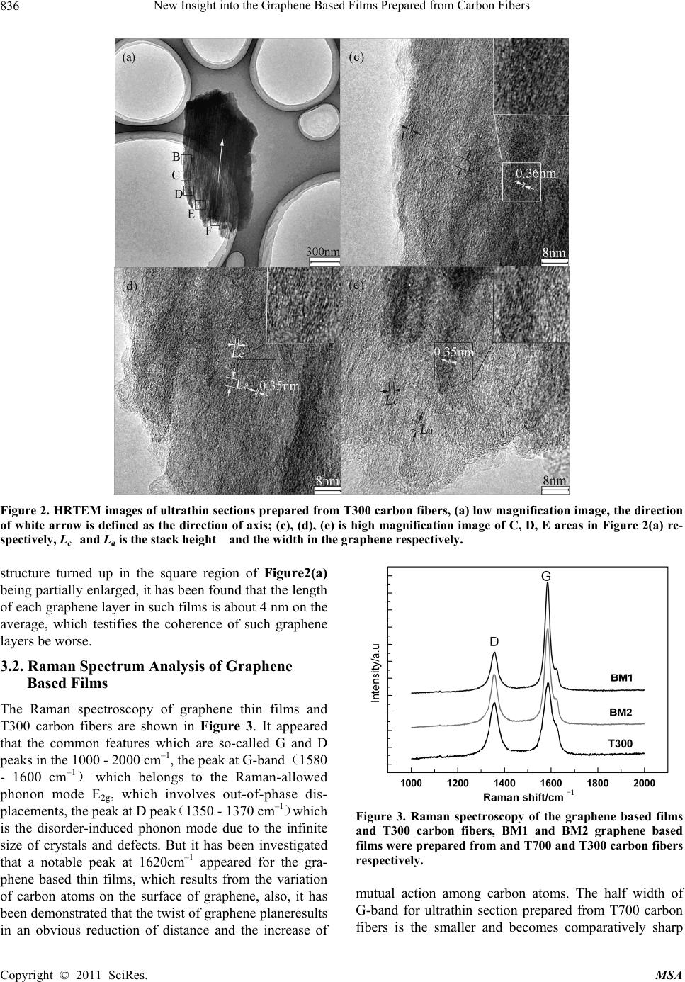 New Insight into the Graphene Based Films Prepared from Carbon Fibers 836 Figure 2. HRTEM images of ultrathin sections prepared from T300 carbon fibers, (a) low magnification image, the direction of white arrow is defined as the direction of axis; (c), (d), (e) is high magnification image of C, D, E areas in Figure 2(a) re- spectively, Lc and La is the stack height and the width in the graphene re spectively. structure turned up in the square region of Figure2(a) being partially enlarged, it has been found that the length of each graphene layer in such films is about 4 nm on the average, which testifies the coherence of such graphene layers be worse. 3.2. Raman Spectrum Analysis of Graphene Based Films The Raman spectroscopy of graphene thin films and T300 carbon fibers are shown in Figure 3. It appeared that the common features which are so-called G and D peaks in the 1000 - 2000 cm–1, the peak at G-band(1580 - 1600 cm–1) which belongs to the Raman-allowed phonon mode E2g, which involves out-of-phase dis- placements, the peak at D peak(1350 - 1370 cm–1)which is the disorder-induced phonon mode due to the infinite size of crystals and defects. But it has been investigated that a notable peak at 1620cm–1 appeared for the gra- phene based thin films, which results from the variation of carbon atoms on the surface of graphene, also, it has been demonstrated that the twist of graphene planeresults in an obvious reduction of distance and the increase of Figure 3. Raman spectroscopy of the graphene based films and T300 carbon fibers, BM1 and BM2 graphene based films were prepared from and T700 and T300 carbon fibers respectively. mutual action among carbon atoms. The half width of G-band for ultrathin section prepared from T700 carbon fibers is the smaller and becomes comparatively sharp Copyright © 2011 SciRes. MSA 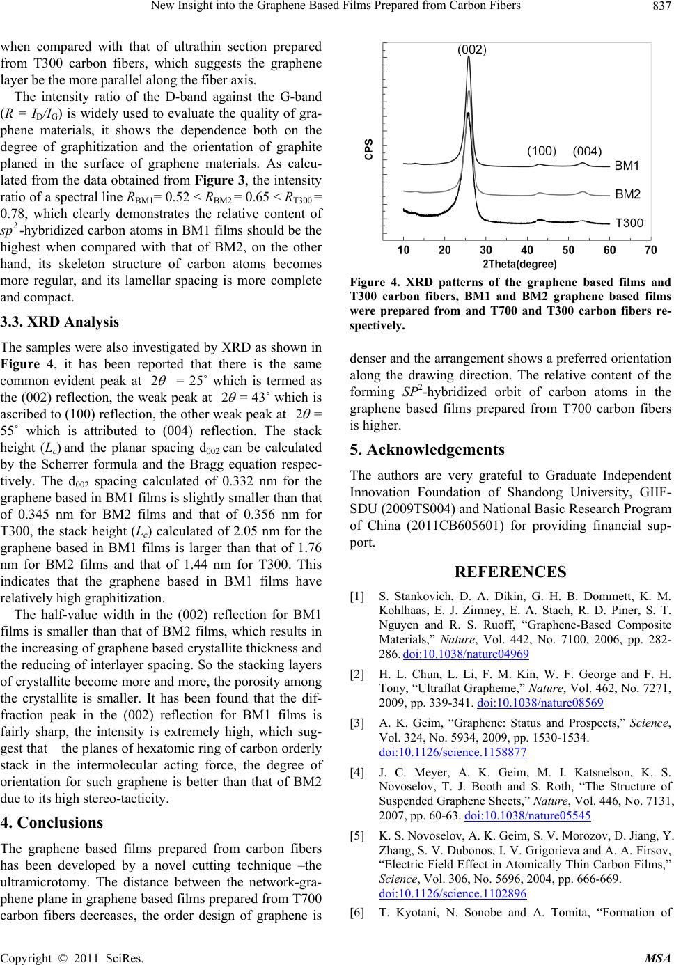 New Insight into the Graphene Based Films Prepared from Carbon Fibers837 when compared with that of ultrathin section prepared from T300 carbon fibers, which suggests the graphene layer be the more parallel along the fiber axis. The intensity ratio of the D-band against the G-band (R = ID/IG) is widely used to evaluate the quality of gra- phene materials, it shows the dependence both on the degree of graphitization and the orientation of graphite planed in the surface of graphene materials. As calcu- lated from the data obtained from Figure 3, the intensity ratio of a spectral line RBM1= 0.52 < RBM2 = 0.65 < RT300 = 0.78, which clearly demonstrates the relative content of sp2 -hybridized carbon atoms in BM1 films should be the highest when compared with that of BM2, on the other hand, its skeleton structure of carbon atoms becomes more regular, and its lamellar spacing is more complete and compact. 3.3. XRD Analysis The samples were also investigated by XRD as shown in Figure 4, it has been reported that there is the same common evident peak at 2 = 25˚ which is termed as the (002) reflection, the weak peak at 2 = 43˚ which is ascribed to (100) reflection, the other weak peak at 2 = 55˚ which is attributed to (004) reflection. The stack height (Lc) and the planar spacing d002 can be calculated by the Scherrer formula and the Bragg equation respec- tively. The d002 spacing calculated of 0.332 nm for the graphene based in BM1 films is slightly smaller than that of 0.345 nm for BM2 films and that of 0.356 nm for T300, the stack height (Lc) calculated of 2.05 nm for the graphene based in BM1 films is larger than that of 1.76 nm for BM2 films and that of 1.44 nm for T300. This indicates that the graphene based in BM1 films have relatively high graphitization. The half-value width in the (002) reflection for BM1 films is smaller than that of BM2 films, which results in the increasing of graphene based crystallite thickness and the reducing of interlayer spacing. So the stacking layers of crystallite become more and more, the porosity among the crystallite is smaller. It has been found that the dif- fraction peak in the (002) reflection for BM1 films is fairly sharp, the intensity is extremely high, which sug- gest that the planes of hexatomic ring of carbon orderly stack in the intermolecular acting force, the degree of orientation for such graphene is better than that of BM2 due to its high stereo-tacticity. 4. Conclusions The graphene based films prepared from carbon fibers has been developed by a novel cutting technique –the ultramicrotomy. The distance between the network-gra- phene plane in graphene based films prepared from T700 carbon fibers decreases, the order design of graphene is Figure 4. XRD patterns of the graphene based films and T300 carbon fibers, BM1 and BM2 graphene based films were prepared from and T700 and T300 carbon fibers re- spectively. denser and the arrangement shows a preferred orientation along the drawing direction. The relative content of the forming SP2-hybridized orbit of carbon atoms in the graphene based films prepared from T700 carbon fibers is higher. 5. Acknowledgements The authors are very grateful to Graduate Independent Innovation Foundation of Shandong University, GIIF- SDU (2009TS004) and National Basic Research Program of China (2011CB605601) for providing financial sup- port. REFERENCES [1] S. Stankovich, D. A. Dikin, G. H. B. Dommett, K. M. Kohlhaas, E. J. Zimney, E. A. Stach, R. D. Piner, S. T. Nguyen and R. S. Ruoff, “Graphene-Based Composite Materials,” Nature, Vol. 442, No. 7100, 2006, pp. 282- 286. doi:10.1038/nature04969 [2] H. L. Chun, L. Li, F. M. Kin, W. F. George and F. H. Tony, “Ultraflat Grapheme,” Nature, Vol. 462, No. 7271, 2009, pp. 339-341. doi:10.1038/nature08569 [3] A. K. Geim, “Graphene: Status and Prospects,” Science, Vol. 324, No. 5934, 2009, pp. 1530-1534. doi:10.1126/science.1158877 [4] J. C. Meyer, A. K. Geim, M. I. Katsnelson, K. S. Novoselov, T. J. Booth and S. Roth, “The Structure of Suspended Graphene Sheets,” Nature, Vol. 446, No. 7131, 2007, pp. 60-63. doi:10.1038/nature05545 [5] K. S. Novoselov, A. K. Geim, S. V. Morozov, D. Jiang, Y. Zhang, S. V. Dubonos, I. V. Grigorieva and A. A. Firsov, “Electric Field Effect in Atomically Thin Carbon Films,” Science, Vol. 306, No. 5696, 2004, pp. 666-669. doi:10.1126/science.1102896 [6] T. Kyotani, N. Sonobe and A. Tomita, “Formation of Copyright © 2011 SciRes. MSA  New Insight into the Graphene Based Films Prepared from Carbon Fibers Copyright © 2011 SciRes. MSA 838 Highly Orientated Graphite from Polyacrylonitrile by Using a Two-Dimensional Space between Montmorillo- nite Lamellae,” Nature, Vol. 331, No. 6154, 1988, pp. 331-333. doi:10.1038/331331a0 [7] G. Eda, G. Fanchini and M. Chhowalla. “Large-Area Ultrathin Films of Reduced Graphene Oxide as a Trans- parent and Flexible Electronic Material,” Nature Nano- technology, Vol. 3, No. 5, 2008, pp. 270-274. doi:10.1038/nnano.2008.83 [8] D. A. Dikin, S. Stankovich, E. J. Zimney, R. D. Piner, G. H. B. Dommett, G. Evmenenko, S. T. Nguyen and R. S. Ruoff, “Preparation and Characterization of Graphene Oxide Paper,” Nature, Vol. 448, No. 7152, 2007, pp. 457- 460. doi:10.1038/nature06016 [9] L. Tapaszto, G. Dobrik, P. Lambin and L. P. Biro, “Tai- loring the Atomic Structure of Graphene Nanoribbons by Scanning Tunnelling Microscope Lithography,” Nature Nanotechnology, Vol. 3, No. 7, 2008, pp. 397-401. doi:10.1038/nnano.2008.149 [10] C. M. Chen, Q. H. Yang, Y. G. Yang, W. Lv, Y. F. Wen, P. X. Hou, M. Z. Wang and H. M. Cheng, “Self-Assem- bled Free-Standing Graphite Oxide Membrane,” Ad- vanced Materials, Vol. 21, 2009, pp. 3007-3011. doi:10.1002/adma.200990138 [11] L. Y. Jiao, X. R. Wang, G. Diankov, H. L. Wang and H. J. Dai, “Facile Synthesis of High-Quality Graphene Nanori- bbons,” Nature Nanotechnology, Vol. 5, No. 5, 2010, pp. 321-325. doi:10.1038/nnano.2010.54 [12] L. J. Ci, L. Song, D. Jariwala, A. L. Elı´as, W. Gao, M. Terrones and P. M. Ajayan, “Graphene Shape Control by Multistage Cutting and Transfer,” Advanced Materials, Vol. 21, 2009, pp. 4487-4491. doi:10.1002/adma.200900942 [13] C. A. Di, D. C. Wei, G. Yu, Y. Q. Liu, Y. L. Guo and D. B. Zhu, “Patterned Graphene as Source/Drain Electrodes for Bottom Contact Organic Field-Effect Transistors,” Advanced Materials, Vol. 20, No. 17, 2008, pp. 3289- 3293. doi:10.1002/adma.200800150 [14] X. L. Li, G. Y. Zhang, X. D. Bai, X. M. Sun, X. R. Wang, E. G. Wang and H. J. Dai, “Highly Conducting Graphene Sheets and Langmuir–Blodgett Films,” Nature Nanotech- nology, Vol. 3, No. 9, 2008, pp. 538-542. doi:10.1038/nnano.2008.210 [15] L. Y. Jiao, L. Zhang, X. R. Wang, G. Diankov and H. J. Dai, “Narrow Graphene Nanoribbons from Carbon Nano- tubes,” Nature, Vol. 458, No. 7240, 2009, pp. 877-880. doi:10.1038/nature07919 [16] G. Y. Zhang, P. F. Qi, X. R. Wang, Y. R. Lu, X. L. Li, R. Tu, S. Bangsaruntip, D. Mann, L. Zhang and H. J. Dai, “Selective Etching of Metallic Carbon Nanotubes by Gas- Phase Reaction,” Science, Vol. 314, 2006, pp. 974-976. doi:10.1126/science.1133781 [17] S. S. Datta, D. R. Strachan, S. M. Khamis and A. T. C. Johnson, “Crystallographic Etching of Few-Layer Gra- phene,” Nano Letter, Vol. 8, 2008, pp. 1912-1915. doi:10.1021/nl080583r [18] Z. S. Wu, “Efficient Synthesis of Graphene Nanoribbons Sonochemically Cut from Graphene Sheets,” Nano Re- search, Vol. 3, No. 1, 2010, pp. 16-22. [19] D. V. Kosynkin, “Longitudinal Unzipping of Carbon Nanotubes to form Graphene Nanoribbons,” Nature, Vol. 458, No. 7240, 2009, pp. 872-876. doi:10.1038/nature07872 [20] C. Lee, X. D. Wei, J. W. Kysar and J. Hone, “Measure- ment of the Elastic Properties and Intrinsic Strength of Monolayer Graphene,” Science, Vol. 321, 2008, pp. 385- 389. doi:10.1126/science.1157996 [21] Y. J. Bai, C. G. Wang, N. Lun, Y. X. Wang, M. J. Yu and B. Zhu, “HRTEM Microstructures of PAN Precursor Fi- bers,” Carbon, Vol. 44, No. 9, 2006, pp. 1773-1778. doi:10.1016/j.carbon.2005.12.041 [22] Y. X. Wang and Q. Wang, “Evaluation of Carbonization Tar in Making High Performance Polyacrylonitrile-Based Carbon Fibers,” Journal of Applied Polymer Science, Vol. 104, 2007, pp. 1255-1259. doi:10.1002/app.25754 [23] R. Perret and W. Ruland, “The Microstructure of PAN- Base Carbon Fibres,” Journal of Applied Crystallography, Vol. 3, No. 6, 1970, pp. 525-532. doi:10.1107/S0021889870006805 [24] S. C. Bennet and D. J. Johnson, “Electron-Microscope Studies of Structural Heterogeneity in PAN-Based Car- bon Fibres,” Carbon, Vol. 17, No. 1, 1979, pp. 25-39. doi:10.1016/0008-6223(79)90067-8 [25] H. Rennhofer, D. Loidl, S. Puchegger and H. Peterlik, “Structural Development of PAN-Based Carbon Fibers Studied by in Situ X-Ray Scattering at High Tempera- tures under Load,” Carbon, Vol. 48, No. 3, 2010, pp. 964-971. doi:10.1016/j.carbon.2009.11.012 |