

Paper Menu >>
Journal Menu >>
 Journal of Surface Engineered Materials and Advanced Technology, 2011, 1, 56-61 doi:10.4236/jsemat.2011.12009 Published Online July 2011 (http://www.SciRP.org/journal/jsemat) Copyright © 2011 SciRes. JSEMAT Development of the Biopolymeric Optical Planar Waveguide with Nanopattern Seung H. Yoon1, Won T. Jeong1, Kyung C. Kim1, Kyung J. Kim2, Min C. Oh2, Sang M. Lee3 1Mechan ical Engineerin g, Pusan National University, Pusan, Korea; 2Electrical Engin eering, Pusan National University, Pusan, Ko- rea; 3Pusan National University, Pusan, Korea. Email: [email protected] Received May 18th, 2011; revised June 15th, 2011; accepted Jun e 25th, 2011. ABSTRACT This paper demonstrates for fabricating the biopolymric optical planar waveguide. Gelatin and chitosan were mixed with ratio of 9 to 1 and sti rred at 70˚C with 1300 rpm. The blended biopolymer was spincoated on silicon substrate with 500 rpm and then dried in the oven at 50˚C. The refractive indices of the prepared biopolymer clad and core layers of the waveguide were measured by the ellipsometry. The measured refractive indices of the two layers were obtained to be 1.516 and 1.52, respectively. The nanograting was successfully imprinted on surface of the biopolymeric waveguide. Keywords: Biopolymeric Optical Waveguide, Nanograting 1. Introduction This work aims to develop highly sensitive all-biopoly- meric planar Bragg grating biosensor. Biopolymer [1-4] is biocompatible material which is developed by blend- ing the chitosan and gelatin [5]. The optical planar wa- veguide is composed of a clad and core layers. The re- fract ive i nd ex o f t he c o re layer is sl ig htl y hi g he r t ha n tha t of the clad layer so that light can be guided in the wave- guide. The Bragg grating is printed on the developed optical planar waveguide by using the nanoimprint tech- nique. 2. Theory This section provides the basic mathematical foundation that will be used to design and perform data analysis of the proposed planar waveguide grating sensor. This sec- tion starts by providing the expressions needed to calcu- late the propagation constants for the slab waveguide in terms of the waveguide geometric and optical properties. Then the coupled mode equations used to determine the grating properties are presented. The waveguide geometry of interest in this paper is illustrated in Figure 1, and consists of a biopolymer core bounded by air above and a biopolymer clad below. This waveguide is fabricated on a silicon substrate. The refractive indices of air, clad and core layers are denoted by n1, n2, and n3 respec- Figure 1. Schematic of the slab waveguide with surface corr ugati on gr a ting. tively and the core thickness is given by tg. Also seen in Figure 1 are the corrugations of pitch and depth a. The most important parameter in the design of Bragg grating in slab waveguide is the effective index. This effective index is found in the usual way [6] by solving the wave equation and applying the continuity boundary condi- tions at the respective core/cladding interfaces of the wave guide s hown i n Figure 1. T he guid ed mod es have a propagation constant βs such that k0n3 < βs < k0n2, where n1 < n3. This solution process lead s to the following tran- scende nt al equation that yields the propagation constant: 2 tanh 1 g pq tpq hh + = − (1) *Korean Government (NRF-2009). 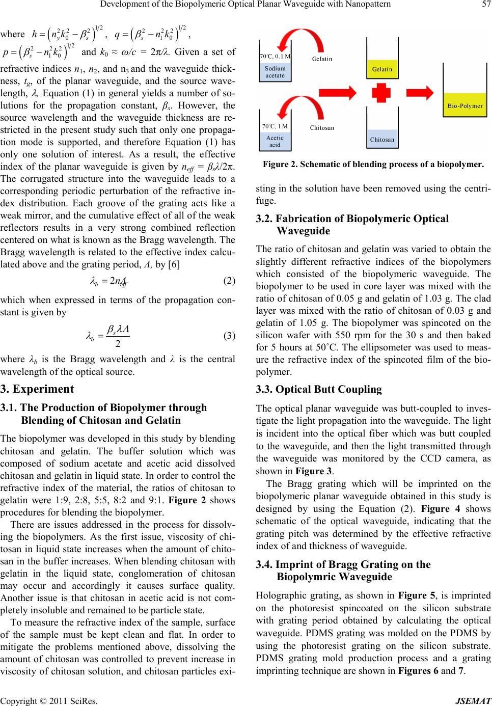 Development of the Biopolymeric Optical Planar Waveguide with Nanopatter n Copyright © 2011 SciRes. JSEMAT 57 where ( ) 12 22 2 0ys h nk β = − , ( ) 12 2 22 10s q nk β = − , ( ) 12 2 22 10s p nk β = − and k0 ≈ ω/c = 2π/λ. Given a set of refractive indices n1, n2, and n3 and the waveguide thick- ness, tg, of the planar waveguide, and the source wave- length, λ , Equation (1) in general yields a number of so- lutions for the propagation constant, βs. However, the source wavelength and the waveguide thickness are re- stricted in the present study such that only one propaga- tion mode is supported, and therefore Equation (1) has only one solution of interest. As a result, the effective index of the planar waveguide is given by neff = βsλ/2π. The corrugated structure into the waveguide leads to a corresponding periodic perturbation of the refractive in- dex distribution. Each groove of the grating acts like a weak mirror, and the cumulative effect of all of the weak reflectors results in a very strong combined reflection centered on what i s kno wn as the B ragg wave le ngth. The Bragg wavelength is related to the effective index calcu- lated above and the grating period, Λ, by [6] 2 b eff nΛ λ = (2) which when expressed in terms of the propagation con- stant is given by 2 s b β λΛ λ = (3) where λb is the Bragg wavelength and λ is the central wavel ength of t he optical sour ce. 3. Experiment 3.1. The Production of Biopolymer through Blending of Chitosan and Gelatin The biopolyme r was de veloped in this stud y by ble nding chitosan and gelatin. The buffer solution which was composed of sodium acetate and acetic acid dissolved chitosan and gelati n in liquid state. In ord er to co ntrol the refractive index of the material, the ratios of chitosan to gelatin were 1:9, 2:8, 5:5, 8:2 and 9:1. Figure 2 shows procedures for blending the biopolymer. There are issues addressed in the process for dissolv- ing the biopolymers. As the first issue, viscosity of chi- tosan in liq uid state increase s when the amount of chito- san i n the buf fer incre ases. W hen ble nding c hitosa n with gelatin in the liquid state, conglomeration of chitosan may occur and accordingly it causes surface quality. Another issue is that chitosan in acetic acid is not com- pletely insoluble and remained to b e par tic le state . To measure the refractive index of the sample, surface of the sample must be kept clean and flat. In order to mitigate the problems mentioned above, dissolving the amount of chitosan was controlled to prevent increase in viscosity of chitosan solution, and chitosan particles exi- Figure 2. Schematic of blending process of a biopo lymer. sting in the solution have b een removed using the centri- fuge . 3.2. Fabrication of Biopolymeric Optical Waveguide The ratio of chitosan and gela tin was varied to ob tain the slightly different refractive indices of the biopolymers which consisted of the biopolymeric waveguide. The biopolymer to be used in core layer was mixed with the ratio of chitosan of 0.05 g and ge lati n of 1 .03 g. The clad layer was mixed with the ratio of chitosan of 0.03 g and gelatin of 1.05 g. The biopolymer was spincoted on the silicon wafer with 550 rpm for the 30 s and then baked for 5 hours at 50˚C. The ellipsometer was used to meas- ure the refractive index of the spincoted film of the bio- polymer. 3.3. Optical Butt Coupling The optical planar waveguide was butt-coupled to inves - tigate the light p ropagation into the waveguide. T he light is incident into the optical fiber which was butt coupled to the waveguide, and then the light transmitted through the waveguide was monitored by the CCD camera, as sho wn in Figure 3. The Bragg grating which will be imprinted on the biopolymeric planar waveguide obtained in this study is designed by using the Equation (2). Figure 4 shows schematic of the optical waveguide, indicating that the grating pitch was determined by the effective refractive index of and thick ness of waveguide. 3.4. Imprint of Bragg Grating on the Biopolymric Waveguide Holographic grating, as shown in Figure 5, is imprinted on the photoresist spincoated on the silicon substrate with grating period obtained by calculating the optical waveguide. PDMS grating was molded on the PDMS by using the photoresist grating on the silicon substrate. PDMS grating mold production process and a grating impr i ntin g tec hni que are shown in F igures 6 and 7. 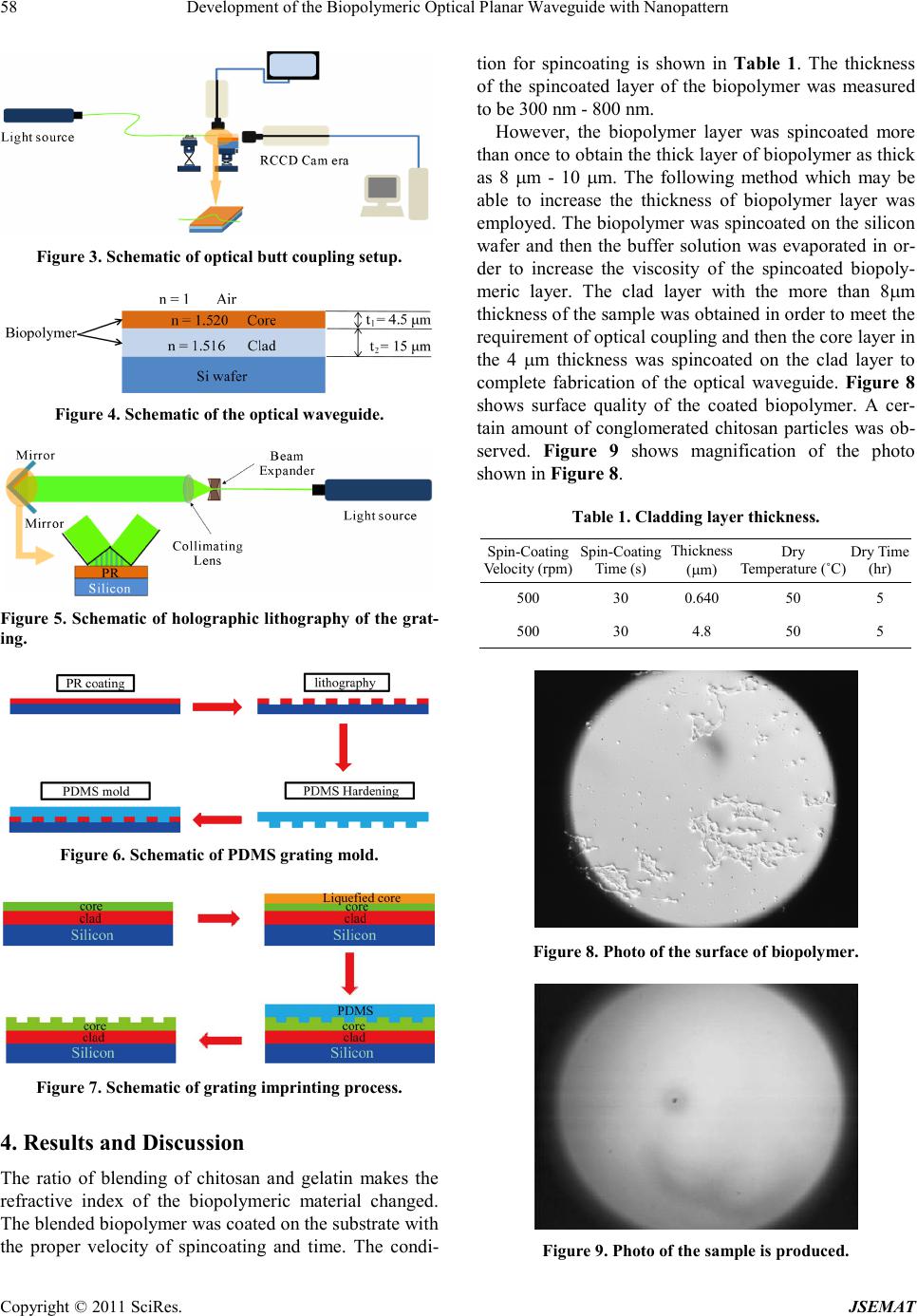 Development of the Biopolymeric Optical Planar Waveguide with Nanopatter n Copyright © 2011 SciRes. JSEMAT 58 Figure 3. Schematic of optical butt coupling setup. Figure 4. Sche matic of the opti cal waveg ui de . Figure 5. Sche matic of holographic lithography of the grat- ing. Figure 6. Sche matic of PDM S grating mol d. Figure 7. Schematic of grating imprinting process. 4. Results and Discussion The ratio of blending of chitosan and gelatin makes the refractive index of the biopolymeric material changed. The blended biopolymer was coated on the substrate with the proper velocity of spincoating and time. The condi- tion for spincoating is shown in Table 1. The thickness of the spincoated layer of the biopolymer was measured to be 300 nm - 800 nm. However, the biopolymer layer was spincoated more than once to obtain the thick layer of biopolymer as thick as 8 µm - 10 µm. The following method which may be able to increase the thickness of biopolymer layer was employed. The biopolymer was spincoated on the silicon wafer and then the buffer solution was evaporated in or- der to increase the viscosity of the spincoated biopoly- meric layer. The clad layer with the more than 8µm thickness o f the sa mple was ob tained in or der to meet the requirement of optical coupling and then the core layer in the 4 µm thickness was spincoated on the clad layer to complete fabrication of the optical waveguide. Figure 8 shows surface quality of the coated biopolymer. A cer- tain amount of conglomerated chitosan particles was ob- served. Figure 9 shows magnification of the photo sho wn in Figure 8. Table 1. Claddi ng layer thickness. Spin-Coating Velocity (rpm) Spin-Coating Time (s) Th ickness (µm) Dry Temperature (˚C) Dry Time (hr) 500 30 0.640 50 5 500 30 4.8 50 5 Figure 8. Photo of t he surface o f biopolymer. Figure 9. Photo of the sample is pro duced.  Development of the Biopolymeric Optical Planar Waveguide with Nanopatter n Copyright © 2011 SciRes. JSEMAT 59 The ellipsometer was used to measure the refractive indices of biopolymer layers. As a result, the measured refractive indices are n = 1.516 for the clad layer and n = 1.520 for the core layer, respectively, as shown in Figure 10. Chan ge in t he ra tio of chi t osan a nd ge lati n ena ble s us adjust the refractive index. The clad thickness of the sample waveguide, which was coupled with the light, was more than 8.5 μm, and the core thickness of the sample was more than 4.5 μm. The transmitted light through the waveguide was meas- ured by using the CCD camera, as sho wn in Figure 11. 5. Conclusions The biopolymric optical planar waveguide and Bragg grating were developed in this study. Gelatin and chito- san were blended with the proper ratio to develop the biopolymers with the different refractive index. The re- fractive indices of the spincoated biopolymer clad and core layers of the waveguide were obtained to be used in the planar waveguide. Then, the Bragg grating was suc- cessfully imprinted on the biopolymeric waveguide. The biopolymeric planar waveguide Bragg grating, which is biocompatible, implantable, and biodegradable, will have Figure 10. Meausred ref ractive index of biopolymer by using the ellipsometer. Figure 11. CCD i mage for light coupl ing measurements. 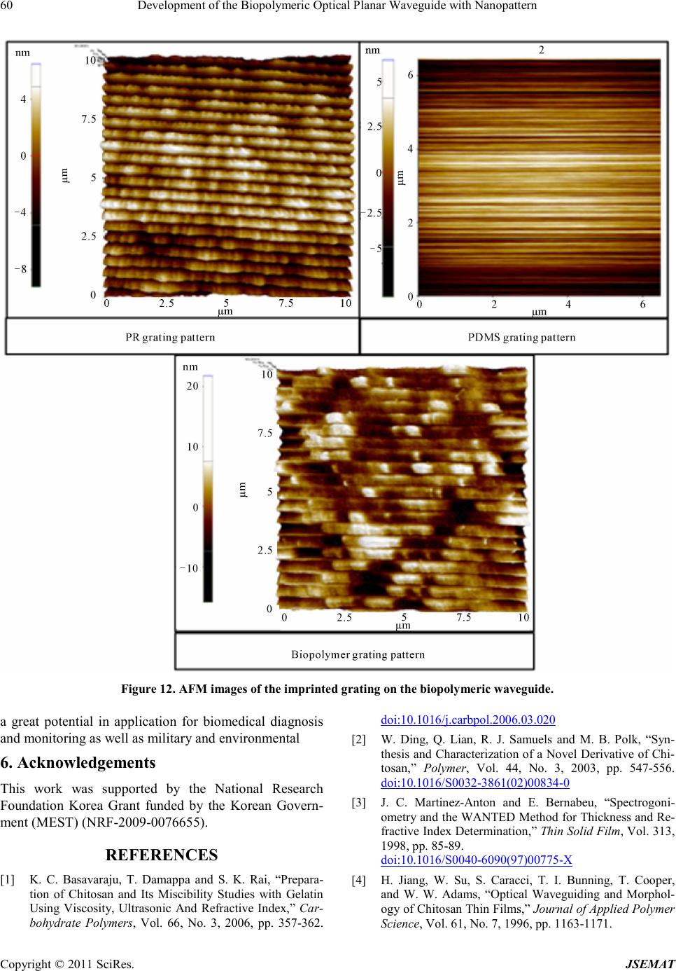 Development of the Biopolymeric Optical Planar Waveguide with Nanopatter n Copyright © 2011 SciRes. JSEMAT 60 Figure 12. AFM images of the imprinted grating on t he biopolymeric waveguide. a great potential in application for biomedical diagnosis and monitoring as well as militar y and environmental 6. Acknowledgements This work was supported by the National Research Foundation Korea Grant funded by the Korean Govern- ment (MEST) (NRF-2009-0076655). REFERENCES [1] K. C. Basavaraju, T. Damappa and S. K. Rai, “Prepara- tion of Chitosan and Its Miscibility Studies with Gelatin Using Viscosity, Ultrasonic And Refractive Index,” Car- bohydrate Polymers, Vol. 66, No. 3, 2006, pp. 357-362. doi:10.1016/j.carbpol.2006.03.020 [2] W. Ding, Q. Lian, R. J. Samuels and M. B. Polk, “Syn- thesis and Characterization o f a Novel Derivativ e of Chi- tosan,” Polym er, Vol. 44, No. 3, 2003, pp. 547-556. doi:10.1016/S0032-3861(02)00834-0 [3] J. C. Martinez-Anton and E. Bernabeu, “Spectrogoni- ometry and the WANTED Method for Thickness and Re- fractive In dex Determinat ion,” Thin Solid Film, Vol. 313, 1998, pp. 85-89. doi:10.1016/S0040-6090(97)00775-X [4] H. Jiang, W. Su, S. Caracci, T. I. Bunning, T. Cooper, and W. W. Adams, “Optical Waveguiding and Morphol- ogy of Chitosan Thin Films,” Journal of Applied Polymer Scien ce, Vol. 61, No. 7, 1996, pp. 1163-1171.  Development of the Biopolymeric Optical Planar Waveguide with Nanopatter n Copyright © 2011 SciRes. JSEMAT 61 doi:10.1002/(SICI)1097-4628(19960815)61:7<1163::AID -APP12>3.0.CO;2-Z [5] K.C. Basavaraju, T. Damappa and S. K. Rai,; “Prepara- tion of Chitosan and Its Miscibility Studies with Gelatin Using Viscosity, Ultrasonic and Refractive Index,” Car- bohydrate Polymers, Vol. 66, No. 3, 20 06, pp. 357-362. doi:10.1016/j.carbpol.2006.03.020 [6] A. Yariv, “Coupled-Mode Theory for Guided - Wave Optics,” IEEE Journal of Quantum Electronics, Vol. 9, No. 9, 1973, p p. 919 -933. doi:10.1109/JQE.1973.1077767 |