

Paper Menu >>
Journal Menu >>
 Communications and Network, 2009, 35-41 doi:10.4236/cn.2009.11005 Published Online August 2009 (http://www.scirp.org/journal/cn) Copyright © 2009 SciRes CN A Cross-Layer Scheme for Handover in 802.16e Network with F-HMIPv6 Mobility Yi ZHENG, Yong ZHANG, Yinglei TENG, Mei SONG Beijing University of Posts and Telecommunications, Beijing, China Email: {zhengyibupt, bjzhangyong, lilytengtt}@gmail.com; [email protected] Abstract: IEEE802.16e is the major global cellular wireless standard that enables low-cost mobile Internet application. However, existing handover process system still has latency affects time-sensitive applications. In this paper, the handover procedures of 802.16e and Fast Handover for Hierarchical MIPv6 (F-HMIPv6) are reconstructed to achieve a better transmission performance. The concept of cross layer design is adopted to refine the existing handover procedure specified in 802.16e MAC layer and F-HMIPv6. More specifically, layer2 and layer3 signaling messages for handover are analyzed and combined/interleaved to optimize the handover performance. Extensive simulations show that the proposed scheme in this paper is superior to the other scheme proposed by IETF. Keywords: handover, cross layer, 802.16e, F-HMIPv6 1. Introduction Recently, wireless access technologies have been evolv- ing for diverse capabilities and services. The Third Gen- eration Partnership Project (3GPP) has been defining Universal Terrestrial Radio Access (UTRA) for 3G radio access,as well as the optimization of the network archi- tecture with HSxPA [1]. The CDMA2000 mobile com- munication system also has been evolved into 1xEV-Dx for high speed data services. As one of wireless access technologies, Mobile WiMAX was successfully adopted by ITU as one of the IMT-2000 technologies in Novem- ber 2007. Since then mobile WiMAX (IP-OFDMA) has officially become a major global cellular wireless stan- dard along with 3GPP UMTS/HSPA and 3GPP2 CDMA/ EVDO [2]. Mobile WiMAX is a fast growing broadband access technology that enables low-cost mobile Internet applica- tions, and realizes the convergence of mobile and fixed broadband access in a single air interface and network architecture. The IEEE802.16e provides high bandwidth, low-cost, scalable solutions that extend services from backbone networks to wireless users. Because of a larger coverage area, portability and mobility have become sig- nificant issues for providing high quality application, as it is crucial to minimize handover latency and maintain ses- sion continuity. The IEEE 802.16e standard only defines a frame work in MAC layer (L2) without considering upper layer handover performance. But from the IP based service point of view, simply reducing the L2 latency does not adequately reduce the overall handover latency. The whole handover procedure shall not include L2 only but also the IP layer. So in order to improve the IP layer (L3) handover performance, a number of standards of MIPv6 are proposed by IETF. Fast Handovers for Mobile IPv6 (FMIPv6) [3], aim to reduce the handover latency by configuring new IP addresses before entering the new subnet. Hierarchical MIPv6 mobility management (HMIPv6) [4] introduces a hierarchy of mobile agents to reduce the registration latency and the possibility of an outdated care-of address. FMIPv6 and HMIPv6 can also be used together as suggested in [5] to reduce the latency related to Movement Detection and CoA configuration/ Verification and cut down the signaling overhead and delay concerned with Binding Update (BU). Fast Hand- over for Hierarchical MIPv6 (F-HMIPv6) [5] also intro- duces the Mobility Anchor Point (MAP) to provide a bet- ter solution for micro mobility. In order to provide seamless services during handover, in this paper, we study the process that shall be performed in L2 and L3 and the related message of 802.16e and F- HMIPv6 to propose a cross layer handoff scheme. In or- der to speed up the total handover process, we also use the proposed scheme in [6] to optimize the 802.16e network entry procedure and reduce the L2 handover delay. This paper is organized as follows. In Section 2 we briefly in- troduce the relevant protocols and related proposals. In Section 3 we present our cross-layer handover scheme, while Section 4 validates its performance. We finally con- clude the paper in Section 5. 2. Background and Related Works 2.1 Handover Process of 802.16e Figure 1 shows the handover process of 802.16e. The 802.16e handover (HO) procedure includes several phases, namely, network topology acquisition and advertisement, target BS scanning procedure, HO decision and initiation, and network re-entry [7]. We provide details about these 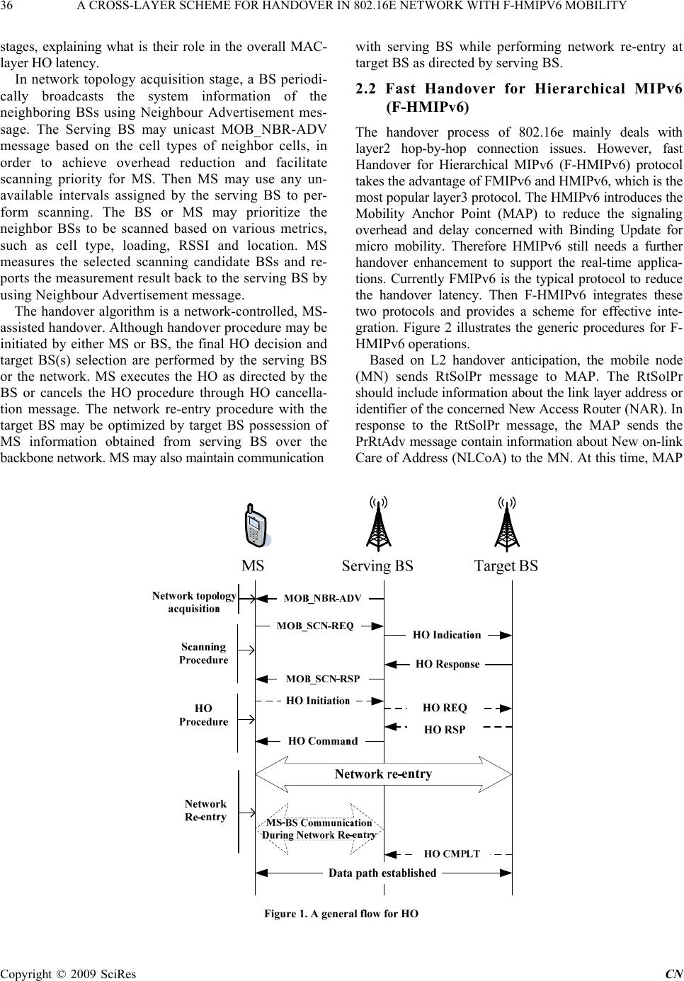 36 A CROSS-LAYER SCHEME FOR HANDOVER IN 802.16E NETWORK WITH F-HMIPV6 MOBILITY stages, explaining what is their role in the overall MAC- layer HO latency. In network topology acquisition stage, a BS periodi- cally broadcasts the system information of the neighboring BSs using Neighbour Advertisement mes- sage. The Serving BS may unicast MOB_NBR-ADV message based on the cell types of neighbor cells, in order to achieve overhead reduction and facilitate scanning priority for MS. Then MS may use any un- available intervals assigned by the serving BS to per- form scanning. The BS or MS may prioritize the neighbor BSs to be scanned based on various metrics, such as cell type, loading, RSSI and location. MS measures the selected scanning candidate BSs and re- ports the measurement result back to the serving BS by using Neighbour Advertisement message. The handover algorithm is a network-controlled, MS- assisted handover. Although handover procedure may be initiated by either MS or BS, the final HO decision and target BS(s) selection are performed by the serving BS or the network. MS executes the HO as directed by the BS or cancels the HO procedure through HO cancella- tion message. The network re-entry procedure with the target BS may be optimized by target BS possession of MS information obtained from serving BS over the backbone network. MS may also maintain communication with serving BS while performing network re-entry at target BS as directed by serving BS. 2.2 Fast Handover for Hierarchical MIPv6 (F-HMIPv6) The handover process of 802.16e mainly deals with layer2 hop-by-hop connection issues. However, fast Handover for Hierarchical MIPv6 (F-HMIPv6) protocol takes the advantage of FMIPv6 and HMIPv6, which is the most popular layer3 protocol. The HMIPv6 introduces the Mobility Anchor Point (MAP) to reduce the signaling overhead and delay concerned with Binding Update for micro mobility. Therefore HMIPv6 still needs a further handover enhancement to support the real-time applica- tions. Currently FMIPv6 is the typical protocol to reduce the handover latency. Then F-HMIPv6 integrates these two protocols and provides a scheme for effective inte- gration. Figure 2 illustrates the generic procedures for F- HMIPv6 operations. Based on L2 handover anticipation, the mobile node (MN) sends RtSolPr message to MAP. The RtSolPr should include information about the link layer address or identifier of the concerned New Access Router (NAR). In response to the RtSolPr message, the MAP sends the PrRtAdv message contain information about New on-link Care of Address (NLCoA) to the MN. At this time, MAP Figure 1. A general flow for HO Copyright © 2009 SciRes CN 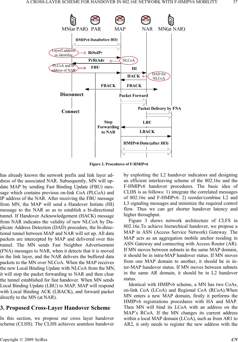 A CROSS-LAYER SCHEME FOR HANDOVER IN 802.16E NETWORK WITH F-HMIPV6 MOBILITY 37 Figure 2. Procedures of F-HMIPv6 has already known the network prefix and link layer ad- dress of the associated NAR. Subsequently, MN will up- date MAP by sending Fast Binding Update (FBU) mes- sage which contains previous on-link CoA (PLCoA) and IP address of the NAR. After receiving the FBU message from MN, the MAP will send a Handover Initiate (HI) message to the NAR so as to establish a bi-directional tunnel. If Handover Acknowledgement (HACK) message from NAR indicates the validity of new NLCoA by Du- plicate Address Detection (DAD) procedure, the bi-direc- tional tunnel between MAP and NAR will set up. All data packets are intercepted by MAP and delivered over this tunnel. The MN sends Fast Neighbor Advertisement (FNA) messages to NAR, when it detects that it is moved in the link layer, and the NAR delivers the buffered data packets to the MN over NLCoA. When the MAP receives the new Local Binding Update with NLCoA from the MN, it will stop the packet forwarding to NAR and then clear the tunnel established for fast handover. When MN sends Local Binding Update (LBU) to MAP, MAP will respond with Local Binding ACK (LBACK), and forward packet directly to the MN (at NAR). 3. Proposed Cross-Layer Handover Scheme In this section, we propose our cross layer handover scheme (CLHS). The CLHS achieves seamless handover by exploiting the L2 handover indicators and designing an efficient interleaving scheme of the 802.16e and the F-HMIPv6 handover procedures. The basic idea of CLHS is as follows: 1) integrate the correlated messages of 802.16e and F-HMIPv6. 2) reorder/combine L2 and L3 signaling messages and minimize the required control flow. Thus we can get shorter handover latency and higher throughput. Figure 3 shows network architecture of CLFS in 802.16e.To achieve hierarchical handover, we propose a MAP in ASN (Access Service Network) Gateway. The MAP acts as an aggregation mobile anchor residing in ASN Gateway and connecting with Access Router (AR). If MN moves between subnets in the same MAP domain, it should be in intra-MAP handover status. If MN moves from one MAP domain to another, it should be in in- ter-MAP handover status. If MN moves between subnets in the same AR domain, it should be in L2 handover status. Identical with HMIPv6 scheme, a MN has two CoAs, on-link CoA (LCoA) and Regional CoA (RCoA).When MN enters a new MAP domain, firstly it performs the HMIPv6 registrations procedures with HA and MAP. Then MN will bind its LCoA with an address on the MAP’s RCoA. If the MN changes its current address within a local MAP domain (LCoA), such as from AR1 to AR2, it only needs to register the new address with the C opyright © 2009 SciRes CN 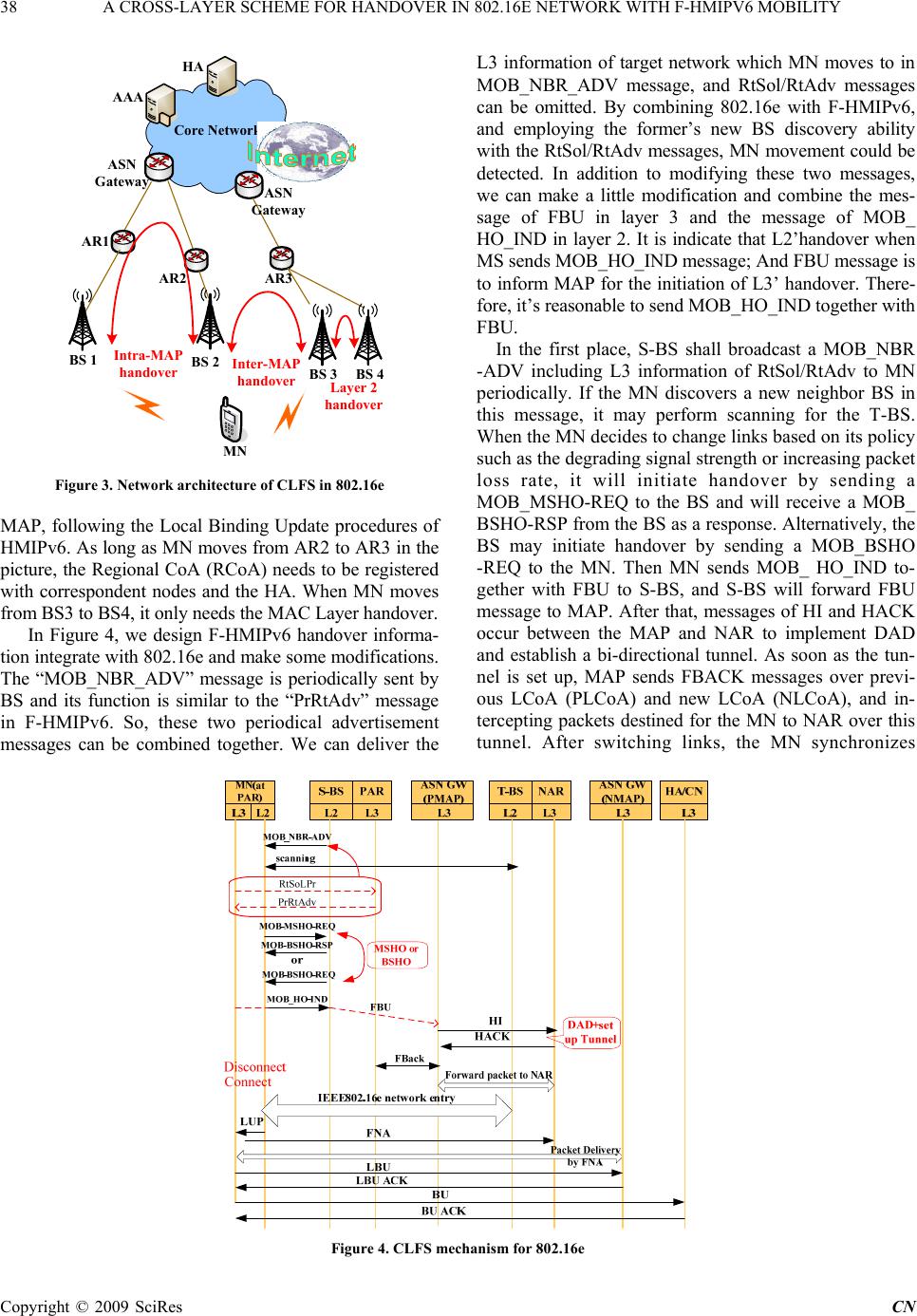 38 A CROSS-LAYER SCHEME FOR HANDOVER IN 802.16E NETWORK WITH F-HMIPV6 MOBILITY Core Network Core Network AAA HA BS 1 BS 3 BS 2 AR3 AR2 AR1 ASN Gateway ASN Gateway Intra-MAP handover Inter-MAP handover MN BS 4 Layer 2 handover Figure 3. Network architecture of CLFS in 802.16e MAP, following the Local Binding Update procedures of HMIPv6. As long as MN moves from AR2 to AR3 in the picture, the Regional CoA (RCoA) needs to be registered with correspondent nodes and the HA. When MN moves from BS3 to BS4, it only needs the MAC Layer handover. In Figure 4, we design F-HMIPv6 handover informa- tion integrate with 802.16e and make some modifications. The “MOB_NBR_ADV” message is periodically sent by BS and its function is similar to the “PrRtAdv” message in F-HMIPv6. So, these two periodical advertisement messages can be combined together. We can deliver the L3 information of target network which MN moves to in MOB_NBR_ADV message, and RtSol/RtAdv messages can be omitted. By combining 802.16e with F-HMIPv6, and employing the former’s new BS discovery ability with the RtSol/RtAdv messages, MN movement could be detected. In addition to modifying these two messages, we can make a little modification and combine the mes- sage of FBU in layer 3 and the message of MOB_ HO_IND in layer 2. It is indicate that L2’handover when MS sends MOB_HO_IND message; And FBU message is to inform MAP for the initiation of L3’ handover. There- fore, it’s reasonable to send MOB_HO_IND together with FBU. In the first place, S-BS shall broadcast a MOB_NBR -ADV including L3 information of RtSol/RtAdv to MN periodically. If the MN discovers a new neighbor BS in this message, it may perform scanning for the T-BS. When the MN decides to change links based on its policy such as the degrading signal strength or increasing packet loss rate, it will initiate handover by sending a MOB_MSHO-REQ to the BS and will receive a MOB_ BSHO-RSP from the BS as a response. Alternatively, the BS may initiate handover by sending a MOB_BSHO -REQ to the MN. Then MN sends MOB_ HO_IND to- gether with FBU to S-BS, and S-BS will forward FBU message to MAP. After that, messages of HI and HACK occur between the MAP and NAR to implement DAD and establish a bi-directional tunnel. As soon as the tun- nel is set up, MAP sends FBACK messages over previ- ous LCoA (PLCoA) and new LCoA (NLCoA), and in- tercepting packets destined for the MN to NAR over this tunnel. After switching links, the MN synchronizes Figure 4. CLFS mechanism for 802.16e Copyright © 2009 SciRes CN 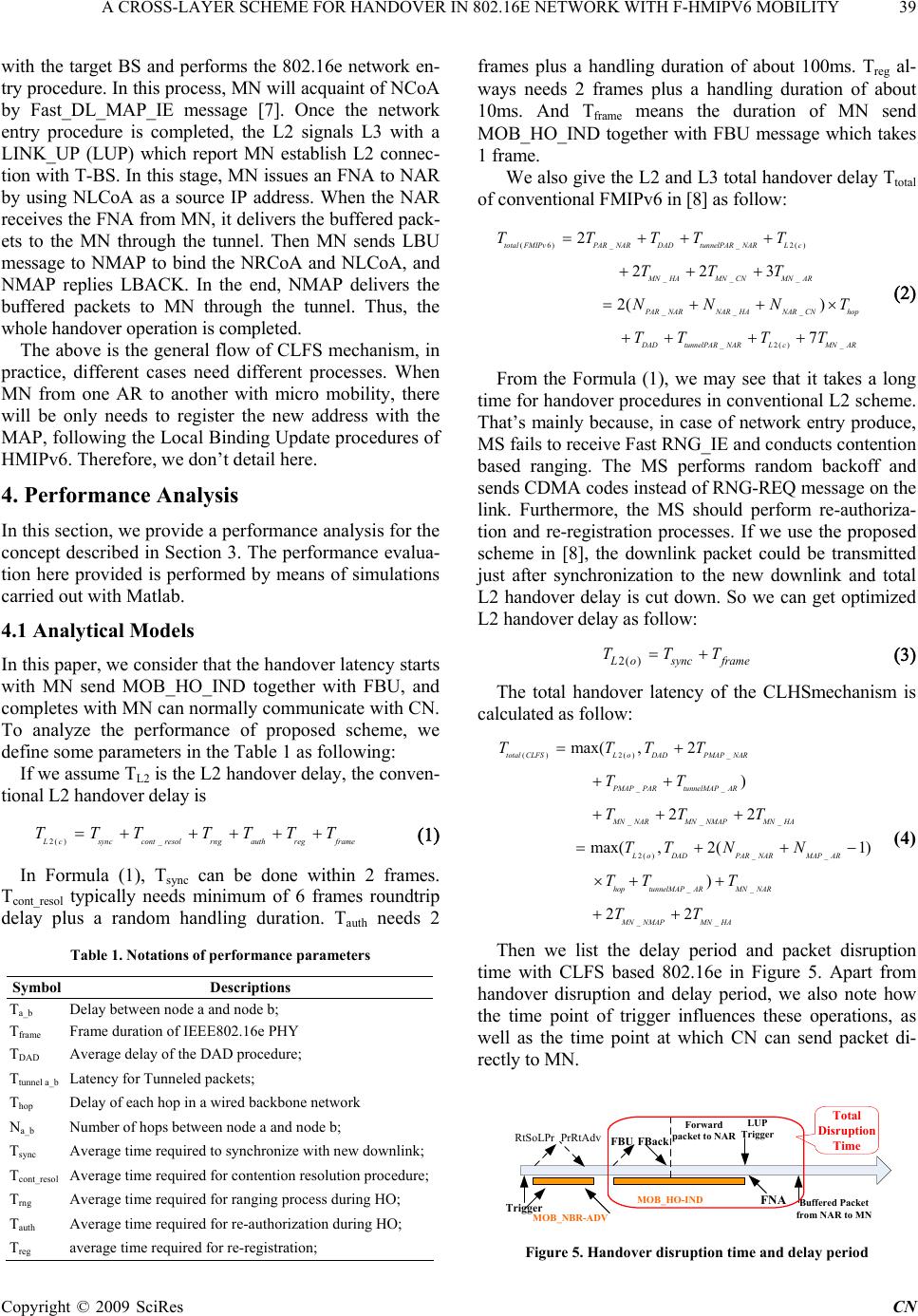 A CROSS-LAYER SCHEME FOR HANDOVER IN 802.16E NETWORK WITH F-HMIPV6 MOBILITY 39 with the target BS and performs the 802.16e network en- try procedure. In this process, MN will acquaint of NCoA by Fast_DL_MAP_IE message [7]. Once the network entry procedure is completed, the L2 signals L3 with a LINK_UP (LUP) which report MN establish L2 connec- tion with T-BS. In this stage, MN issues an FNA to NAR by using NLCoA as a source IP address. When the NAR receives the FNA from MN, it delivers the buffered pack- ets to the MN through the tunnel. Then MN sends LBU message to NMAP to bind the NRCoA and NLCoA, and NMAP replies LBACK. In the end, NMAP delivers the buffered packets to MN through the tunnel. Thus, the whole handover operation is completed. The above is the general flow of CLFS mechanism, in practice, different cases need different processes. When MN from one AR to another with micro mobility, there will be only needs to register the new address with the MAP, following the Local Binding Update procedures of HMIPv6. Therefore, we don’t detail here. 4. Performance Analysis In this section, we provide a performance analysis for the concept described in Section 3. The performance evalua- tion here provided is performed by means of simulations carried out with Matlab. 4.1 Analytical Models In this paper, we consider that the handover latency starts with MN send MOB_HO_IND together with FBU, and completes with MN can normally communicate with CN. To analyze the performance of proposed scheme, we define some parameters in the Table 1 as following: If we assume TL2 is the L2 handover delay, the conven- tional L2 handover delay is 2( )_ L csynccont resolrngauthregframe TTT TTTT In Formula (1), Tsync can be done within 2 frames. Tcont_resol typically needs minimum of 6 frames roundtrip delay plus a random handling duration. Tauth needs 2 Table 1. Notations of performance parameters Symbol Descriptions Ta_b Delay between node a and node b; Tframe Frame duration of IEEE802.16e PHY TDAD Average delay of the DAD procedure; Ttunnel a_b Latency for Tunneled packets; Thop Delay of each hop in a wired backbone network Na_b Number of hops between node a and node b; Tsync Average time required to synchronize with new downlink; Tcont_resol Average time required for contention resolution procedure; Trng Average time required for ranging process during HO; Tauth Average time required for re-authorization during HO; Treg average time required for re-registration; frames plus a handling duration of about 100ms. Treg al- ways needs 2 frames plus a handling duration of about 10ms. And Tframe means the duration of MN send MOB_HO_IND together with FBU message which takes 1 frame. We also give the L2 and L3 total handover delay Ttotal of conventional FMIPv6 in [8] as follow: (6)__ 2() ___ ___ _2()_ 2 223 2( ) 7 totalFMIPvPARNAR DAD tunnelPARNAR Lc MN HAMN CNMNAR PAR NARNAR HANAR CNhop D ADtunnelPAR NARLcMNAR TTTTT TTT NNN TTT T T From the Formula (1), we may see that it takes a long time for handover procedures in conventional L2 scheme. That’s mainly because, in case of network entry produce, MS fails to receive Fast RNG_IE and conducts contention based ranging. The MS performs random backoff and sends CDMA codes instead of RNG-REQ message on the link. Furthermore, the MS should perform re-authoriza- tion and re-registration processes. If we use the proposed scheme in [8], the downlink packet could be transmitted just after synchronization to the new downlink and total L2 handover delay is cut down. So we can get optimized L2 handover delay as follow: 2( ) Losyncframe TTT The total handover latency of the CLHSmechanism is calculated as follow: () 2()_ __ __ _ 2( )__ __ __ max( ,2 ) 22 max( ,2(1) ) 22 total CLFSLoDADPMAPNAR PMAP PARtunnelMAP AR MNNARMNNMAPMNHA LoDADPAR NARMAPAR hoptunnelMAP ARMN NAR MN NMAPMN HA TTTT TT TT T TT NN TT T TT (4) Then we list the delay period and packet disruption time with CLFS based 802.16e in Figure 5. Apart from handover disruption and delay period, we also note how the time point of trigger influences these operations, as well as the time point at which CN can send packet di- rectly to MN. Trigger MOB_NBR-ADV RtSoLPr PrRtAdvFBU FBack Forward packet to NAR MOB_HO-IND LUP Trigger FNA Buffered Packet from NAR to MN Total Disruption Time Figure 5. Handover disruption time and delay period C opyright © 2009 SciRes CN 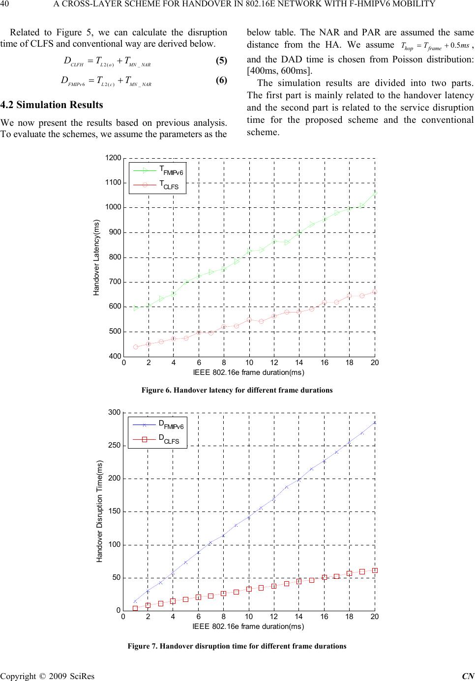 40 A CROSS-LAYER SCHEME FOR HANDOVER IN 802.16E NETWORK WITH F-HMIPV6 MOBILITY Related to Figure 5, we can calculate the disruption time of CLFS and conventional way are derived below. 2( )_CLFHLoMNNAR DTT (5) 62() _ F MIPvLcMN NAR DTT (6) 4.2 Simulation Results We now present the results based on previous analysis. To evaluate the schemes, we assume the parameters as the below table. The NAR and PAR are assumed the same distance from the HA. We assume , and the DAD time is chosen from Poisson distribution: [400ms, 600ms]. 0.5 hop frame TT ms The simulation results are divided into two parts. The first part is mainly related to the handover latency and the second part is related to the service disruption time for the proposed scheme and the conventional scheme. 0246810 121416 18 20 400 500 600 700 800 900 1000 1100 1200 IEEE 802.16e frame duration(ms) Handover Latency(ms) T FMIPv6 T CLFS Figure 6. Handover latency for different frame durations 024681012 14 16 1820 0 50 100 150 200 250 300 IEEE 802.16e frame duration(ms) Handover Disruption Time(ms) DFMIPv6 DCLFS Figure 7. Handover disruption time for different frame durations Copyright © 2009 SciRes CN 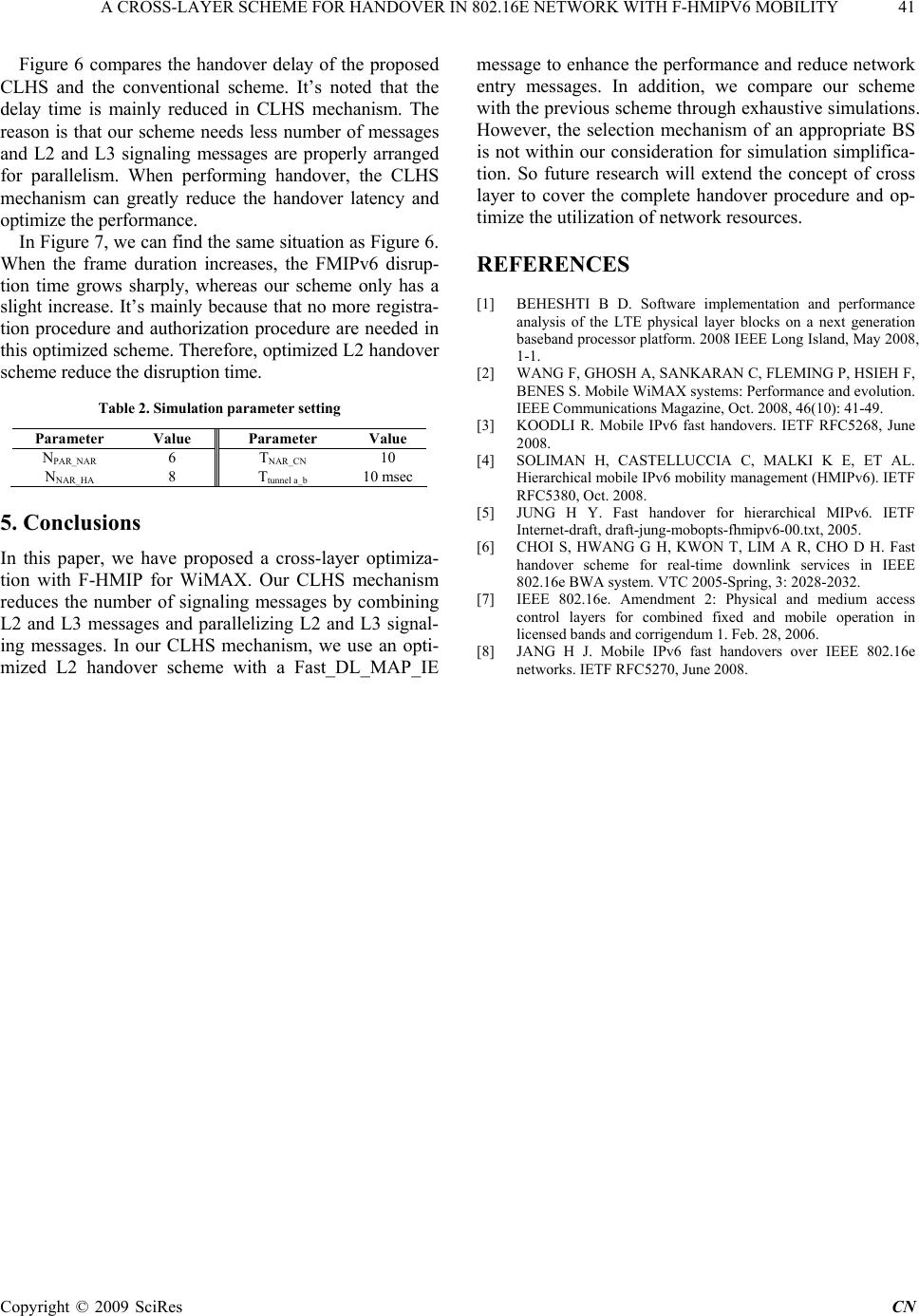 A CROSS-LAYER SCHEME FOR HANDOVER IN 802.16E NETWORK WITH F-HMIPV6 MOBILITY 41 Figure 6 compares the handover delay of the proposed CLHS and the conventional scheme. It’s noted that the delay time is mainly reduced in CLHS mechanism. The reason is that our scheme needs less number of messages and L2 and L3 signaling messages are properly arranged for parallelism. When performing handover, the CLHS mechanism can greatly reduce the handover latency and optimize the performance. In Figure 7, we can find the same situation as Figure 6. When the frame duration increases, the FMIPv6 disrup- tion time grows sharply, whereas our scheme only has a slight increase. It’s mainly because that no more registra- tion procedure and authorization procedure are needed in this optimized scheme. Therefore, optimized L2 handover scheme reduce the disruption time. Table 2. Simulation parameter setting Parameter Value Parameter Value NPAR_NAR 6 TNAR_CN 10 NNAR_HA 8 Ttunnel a_b 10 msec 5. Conclusions In this paper, we have proposed a cross-layer optimiza- tion with F-HMIP for WiMAX. Our CLHS mechanism reduces the number of signaling messages by combining L2 and L3 messages and parallelizing L2 and L3 signal- ing messages. In our CLHS mechanism, we use an opti- mized L2 handover scheme with a Fast_DL_MAP_IE message to enhance the performance and reduce network entry messages. In addition, we compare our scheme with the previous scheme through exhaustive simulations. However, the selection mechanism of an appropriate BS is not within our consideration for simulation simplifica- tion. So future research will extend the concept of cross layer to cover the complete handover procedure and op- timize the utilization of network resources. REFERENCES [1] BEHESHTI B D. Software implementation and performance analysis of the LTE physical layer blocks on a next generation baseband processor platform. 2008 IEEE Long Island, May 2008, 1-1. [2] WANG F, GHOSH A, SANKARAN C, FLEMING P, HSIEH F, BENES S. Mobile WiMAX systems: Performance and evolution. IEEE Communications Magazine, Oct. 2008, 46(10): 41-49. [3] KOODLI R. Mobile IPv6 fast handovers. IETF RFC5268, June 2008. [4] SOLIMAN H, CASTELLUCCIA C, MALKI K E, ET AL. Hierarchical mobile IPv6 mobility management (HMIPv6). IETF RFC5380, Oct. 2008. [5] JUNG H Y. Fast handover for hierarchical MIPv6. IETF Internet-draft, draft-jung-mobopts-fhmipv6-00.txt, 2005. [6] CHOI S, HWANG G H, KWON T, LIM A R, CHO D H. Fast handover scheme for real-time downlink services in IEEE 802.16e BWA system. VTC 2005-Spring, 3: 2028-2032. [7] IEEE 802.16e. Amendment 2: Physical and medium access control layers for combined fixed and mobile operation in licensed bands and corrigendum 1. Feb. 28, 2006. [8] JANG H J. Mobile IPv6 fast handovers over IEEE 802.16e networks. IETF RFC5270, June 2008. C opyright © 2009 SciRes CN |