

Paper Menu >>
Journal Menu >>
 Engineering, 2013, 5, 590-594 http://dx.doi.org/10.4236/eng.2013.510B121 Published Online October 2013 (http://www.scirp.org/journal/eng) Copyright © 2013 SciRes. ENG Effects of Tube Voltage on Phase-Contrast Imagin g for Different Microfocus X -Ray Tubes* Jianbao Gui, Z hanli Hu, Peter Z. Wu, Hairong Zheng Paul C . Lauterbur Research Center for Biomedical Imaging, Institute of Biomedical and Health Engineering, Shenzhen Institutes of Advanced Technology, Chinese Academy of Sciences, Shenzhen, China Email: [email protected], hr.zheng@si at.ac.cn Received 2013 ABSTRACT In the past decade, phase-contrast imaging (PCI) has beco me a hot research with an increased improvement of the im- age contrast with respect to conventional absorption radiography. In this paper, effects of tube volta ge (kVp ) on propa- gation-based phase-contrast imaging have been investigated with two types of microfocus x-ray tubes, a conventional sealed x-ray tube with the focal spot size of 13 - 20 μm and an open x-ray tube with minimum focal spot size less than 2 μm. A cooled x-ray CCD detector with the pixel size of 24 μm was used to acquire digital images. Two thin plastic sheets with different thickness were used as radiography phantoms. Two different phenomena were observed for the t wo x -r a y t ub e s. For the o pen tub e, p hase -contr a st e ffect has a sli ght dr op with the incr ea si ng of t ub e volt age , ho weve r, it is opposite for the sealed tube. A further investigation indicates that the variation of focal spot size causes the abnor- mal result for the sealed tube. It also s hows t hat pha se-contrast effect is more sensitive to focal spot size than tube vol- tage. Keywords: Phase-Contrast Imaging; Edge Enhancement ; X-Ray; Tube V oltage 1. Introduction Conventional x-ray imaging is based on the attenuation properties of an object, however, for some weak absorp- tion objects, such as biological tissue, polymers, and fi- ber composites, the use of conventional x-ray imaging is limited due to poor image con trast. While the applica tion of x-ray phase-contrast imaging can provide a way to generate the images with better image-contrast because the interaction cross-section of x-ray phase-shift is about a thousand times larger than that of absorption for soft tissues [1]. Wilkins and his colleague firstly developed a classical theory formula (PGW theory) [2] on propagation-based phase-contrast imaging (PB-PCI) in 1997. This PGW theory is based on the paraxial Fresnel–Kirchhoff dif- fraction for spatially coherent x-ray sourc es . I n 2 00 4 , W u and Liu publicized a more comprehensive theory based on Wigner distribution function (WDF) [3], which can deal with partiallycoherent x-ray and the detector’s im- pact. According to the PGW theory, for a weak absorp- tion and weak phase-shi ft object, ( )( ) 2 12 ee I xrzx λρ π ′′ ≈− , (1) where re is the classical electron radius and ρe the pro- jected electron density, λ denotes the wavelength and z the propagation distance. From the formula, we can know that a longer wavelength and a larger propagation distance are helpful to the forming of phase contrast, which means a lower x-ray energy expected. We can also consider phase-contrast effect from lateral coherence length for the PB-PCI d ep end i ng o n a p ar tia ll y coherence microfocus x-ray source, 1 dR λσ λγ ⊥ = = , (2) where σ is the source size, γ is the angular width of the source as viewed from the observation point. The lateral coherence length is larger, phase-contrast effect is better. Fro m this wa y, we ca n se e t hat l on ger wavel engt hs (lo w- er x-ray energies), longer SOD distances and smaller focus-spot sizes, are beneficial for the phase-contrast imaging. Donnelly investigated some influencing factors by ex- periments based on different PCI systems [4-6]. It is in- teresting that Donnelly showed that phase enhancement effect had a slightl y drop with the increa sing of t ube vo l- tage ( kVp) in t his p ap er [4 ], but the a utho r als o sho wed a * This work was supported in part by National Science & Technology Pillar Progr am (2012B AI13B 04), Nation al Natural Sci ence Foundati on of China (81401410), Special Fund Project and Basic Research Pr o- gram of Shenzhen ( CXZZ20140505091419405, JCYJ201304011703 06796, JCYJ20140 417113430558 , JCYJ20130401170306880).  J. B. GUI ET AL. Copyright © 2013 SciRes. ENG 591 different result that phase enhancement effect essentially wasn’t affected as the tube voltage increased in other two papers [5,6]. In this paper, we had a detail experimental investiga- tion on the effect of tube voltage on phase-contrast im- aging. This stud y was ba sed on two t ypes o f x-r ay t ube s, a sealed microfocus x-ray tube and an openmicrofocus x-ray tube, and the later has some better properties suita- ble for PCI study, for example, smaller and adjustable focal spot sizes, higher kVps and higher powers. The study is significant for optimizing system design and ex- ploring common rules of the PB-PCI technology. 2. Materials and Methods Two investigations were performed based on a conven- tional sealed x-ray source (UltraBright, Oxford Instru- ments) and an open x-ray source (FXE 160.51, YXLON), respectively. The sealed x-ray source has a focal spot size of 13 - 20 μm, tube voltage and tube power can been adjusted in the range of 20 - 90 kVp and 10 - 19 W, re- spectively. The open x-ray source has a minimum focal spot size less than 2 μm and the focal spot size can been adjusted by changing the focusing current, which is the current flowing through the focusing lenses. The tube voltage (kVp) can be varied from 20 to 160 kVp, maxi- mum tube power and target power is 64 W and 10 W, respectively. A cooled x-ray CCD imaging detector (Quad-RO 4320, Princeton Instruments) was used to ac- quire the images. The CCD imaging detector has a high spatial resolution, large active imaging area and low noise (24 μm pixel size, 2084 × 2084 array and 50 × 50 mm2 active area, ultra low noise electronics and state-of- the-art cooling technology), these characteristics are also helpful for phase-contrast i maging investigation. The source- to-detector distance (SDD) was held at 710 mm and the SOD could be adjusted from 10 to 510 mm. In order to quantify the edge enhancement effect of phase-contrast imaging, we adopted the same edge en- hancement index (EEI) as Donnelly [4]. The EEI is de- fined as follows: () () () ( ) PT PT EEI HL HL −+ =−+ , (3) where P and T are t he peak and tro ugh intensity values at the ed ge, and H and L are average values of multi-pixels on the high- and low-intensity regions next to the edge. Two other indexes [4] were also evaluated: the up- stroke index (U I), defined as fo llows: UI = (P − H)/(P + H), (4) and the downstr oke ind ex (DI), d efined as follo ws: DI = (L − H)/(L + H). (5) For the sealed x-ray tube, we have performed the im- aging at different x-ray tube voltages with constant tube power of 10 W. In order to focus on the edge-enhanced phenomenon, a thin rectangular plastic sheet of 0.5 mm thickness was used as a radiography phantom. The SOD was kept at 185 mm and exposure time was 8 s. For the open x-ray tube, to evaluate the effect of the tube voltage, two sets of experiments were performed. In the first one, the target power was held constant at 3 W and the tube voltage was adjusted. In the second one, target current was held constant at 30 μA and the tube voltage was adjusted. The SOD was held at 40 mm and exposure time was adjusted to maintain an approximate constant exposure intensity. A plastic sheet of 2 mm thickness was used as a radiography phantom. The image at each kVp was obtained by averaging 5 frames acquired continuously and profiles of pixel inten- sity values were obtained by averaging 50 continuous rows to reduce noise. Quantitative indexes UI, DI and EEI were computed for all images. 3. Results and Discussions 3.1. Sealed X-Ray Tube Depending on the sealed type x-ray tube (UltraBright, Oxford Instruments), the phase-contrast image of the 0.5 mm thickness plastic phantom was acquired at a repre- sentative tube voltage of 50 kVp, as shown in Fig ure 1(a). From the image we can see obvious edge-enhance- ment (high- and l o w-intensity ver tical lines) at t wo ed ges of the phanto m. The pr ofiles along the middle hor izontal line of the images obtained at different tube voltages are shown in Figure 1(b). It is interesting to note that this effect is more pronounced at a higher kVp value. The quantitative upstroke index shows the same result that edge enhancement becomes more pro nounc ed a s the kV p increases. It is contrary to the common belief that better phase- contrast occurs at the lower energy since the longer wa- velength o f x-ray photos at a lo wer tube voltage can im- prove the phase-contrast. Fortunately, the variation of focal-spot size at d ifferent ope ration conditions, which is observed in the other experiments, inspires us to think about the effect focal-spot size on the phase-contrast im- aging. In order to quantify the size of the focal spot in our system, we imaged a JIMA (Japan Inspection Instru- ments Manufacturers’ Association) resolution test-pattern with the micro-focus x-ray system. By using the resolu- tion test-pattern, the acquired images at different tube voltages are shown in Figure 2, from which it is seen that the spatial resolution of the images becomes better with the increase of kVp value. It means that the varia- tion of focal-spot size causes the abnormal phenomenon, though a higher tube voltage can decrease the edge en- 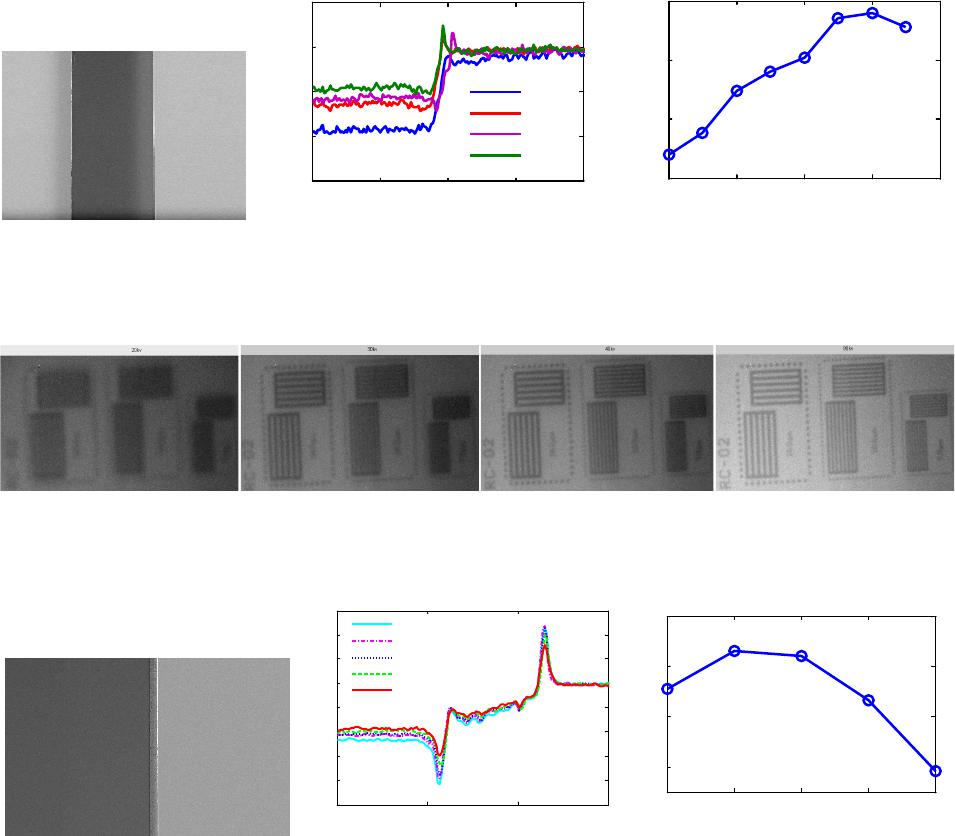 J. B. GUI ET AL. Copyright © 2013 SciRes. ENG 592 hancement, the effect of focal-spot size is greater. From our results, it can be derived that phase-contrast effect is insensitive to tube voltage (or equivalently, wavelength of x -ray photos), but sensitive to focal-spot siz e. 3.2. Open X-Ray Tube 3.2.1. Constant Target Power Figure 3(a) shows the phantom image obtained at 80 kVp when a constant target power of 3 W was held. Representative profiles of the pixel intensity values across the edge images obtained at different tube voltag- es are shown in Figure 3(b). EEI as a function of kVp are shown in Fig ure 3(c). These indicate a different re- sult that edge enhancement drops as kVp increases. In Figure 4, images of JIMA resolution test-pattern show that the spatial resolutions are almost same at different kVp. 3.2.2. Constant Target Current Whena constant target current was held, representative profiles of the pixel intensity values across the edge im- ages obtained at different tube voltages are shown in Figure 5(a). EEI as a function of tube voltage are shown in Figure 5(b). These results also show that edge en- hancement has a drop as the kVp increases. In Figure 6, images of JIMA resolution test-pattern shows the spatial resolutions are almost same at different kVp. (a) (b) (c) Figure 1 . (a) The 0.5 mm plastic edge phantom image obtained at 50 kVp a n d t he S OD o f 1 8 5 mm, ( b) re pr e se nt ative pr of il es near to the rig ht edge at dif ferent tube volt ages and (c) EEI as a f untio n of kVp. The t ube p ower was he ld cons tant at 10 W. This resul t was obtai ned based on the sealed type x-ray tube (UltraBright, Oxford Instruments). (a) (b) (c) (d) Figure 2. Representative images of the JIMA resoluti on test- patter n a t different tube voltage, 20 kVp, 30 kVp, 40 kVp and 90 kVp, display window is [0.9, 1.5]. All images were acquired at the tube power of 10 W. The resolution pattern from left to right in every figure is 15, 10 and 7 μm, respectively. (a ) 20 kV p, 10 W; (b ) 30 kV p , 10 W ; (c) 40 kV p , 10 W ; (d) 90 kV p , 10 W. (a) (b) (c) Figure 3. (a) The 2 mm plastic edge phantom image obtained at 80 kVp and the SOD of 40 mm, (b) representative profiles near to the edge at different tube voltages and (c) EEI as a funtion of kVp. The tube power w as held const ant at 3 W. This result was obtained based on the open type x-ray tube (FXE 160.51, YXLON). 1200 1250 1300 1350 1400 0.85 0.9 0.95 1 1.05 Pix e ls Relati ve intensity 20 kVp 40 kVp 60 kVp 90 kVp 20 40 60 80 100 0 0.005 0.01 0.015 Tube vol tage (kVp) Upstroke index 1000 1050 1100 1150 0.75 0.8 0.85 0.9 0.95 1 1.05 1.1 Pix el Relative intensit 40 kVp, 75 µA 60 kVp, 50 µA 80 kVp, 37.5 µA 100 kVp, 30 µA 120 kVp, 25 µA 40 60 80100 120 2.4 2.6 2.8 3 Tube Voltage(kVp) Edge E nhancement Index  J. B. GUI ET AL. Copyright © 2013 SciRes. ENG 593 (a) (b) (c) Figure 4. I mages of JIM A res o lution test-pattern at different tube voltages with constant target power, (a) 40 kVp, (b) 80 kVp, (c) 120 kVp. All images show the same spatial resoltion of 3 μm. (a) (b) Figure 5. (a) Representative profiles near to the edge at different tube voltages and (b) EEI as a funtion of kVp. The target curr ent was held constant at 30 μA. This result was obtained based on the open type x-ray tube (FXE 160.51, YXLON). (a) (b) (c) Figure 6. Ima ges of JIMA resolution test-pattern at different tube voltage with constant target current, (a) 40 kVp, (b) 80 kVp and (c) 120 kVp. All i mages sho w the same spatial resoltion of 3 μm. Both the study at constant target power and the study at constant target current demonstrate that edge en- hancement has a drop wit h the increa s ing of t ube vol t age, but the drop is slight since the edge enhancement at the high voltage of 120 kVp is still obvious. This result is consistent with the PGW theory and lateral coherence length formula, longer wavelength (lower x-ray energy) is beneficial for the phase-contrast imaging. The use of high tube voltages over 100 kVp is very significant in reducing patient dose if the phase-contrast imaging technology will be applied in human breast diagnosis in the future. 4. Conclusion We investigated the effect of tube voltage (kVp) on the propagation-based phase-contrast imaging with two types of microfocus x-ray tubes, a conventional sealed x-ray tube and an open x-ray tube. Two different phenomena were observed for the two x-r ay tube s . For t he o p en t ub e , phase-contrast effect has a slight drop with the increasing of tube voltage, however, it is opposite for the sealed tube. A further investigation indicates that the variation of focal spot size causes the abnormal result for the sealed tube. It also shows that phase-contrast effect is more sensitive to focal spot size than tube voltage. 1000 1050 1100 1150 0.8 0.9 1 1.1 Pix el Relative intensit 40 k Vp 60 k Vp 80 k Vp 100 k Vp 120 k Vp 40 60 80 100 120 2.2 2.4 2.6 2.8 3 Tube Voltage(kVp) Edge Enhancement Index  J. B. GUI ET AL. Copyright © 2013 SciRes. ENG 594 REFERENCES [1] X. Z. Wu and H. Li u, “Clini cal Implementation of X-Ray Phase-Contrast Imaging: Theoretical Foundations and Design Considerations,” Medical Physics, Vol. 30, No. 8, 2003, pp. 2169-2179. http://dx.doi.org/10.1118/1.1593836 [2] A. Pogany, D. Gao and S. W. Wilkins, “Contrast and Resolution in Imaging with a Microfocus X-Ray Source,” Review of Scientific Instruments, Vol. 68, No. 7, 19997, pp. 2774-2782. http://dx.doi.org/10.1063/1.1148194 [3] X. Z. Wu and H. Liu, “Phase-Space Formulation for Phase- Contrast X-Ray Imaging,” Applied Optics, Vol. 44, No. 28, 2005 , pp. 5847-5854. http://dx.doi.org/10.1364/AO.44.005847 [4] F. D. Edwin and R. P. Ronald, “Quantification of the Effect of kVp on Edge-Enhancement Ind ex in Phase-Con- trast Rad io graph y,” Medica l Ph ysics, Vol. 29, No. 6, 2002, pp. 999-1002. http://dx.doi.org/10.1118/1.1477416 [5] F. D. Edwin, et al., “Characterization of the Phase-Con- trast Radiography Edge-Enhancement Effect in a Cabinet X-Ray System,” Physics in Medicine and Biology, Vol. 51, No. 1, 2006 , p. 21. http://dx.doi.org/10.1088/0031-9155/51/1/002 [6] F. D. Edwin, R. P. Ronald and R. P. David, “Quantifica- tion of the Effect of System and Object Parameters on Edge Enhancement in P hase-Contrast Radiography,” Medical Physics, Vol. 30, No. 11, 2003, pp. 2888-2896. http://dx.doi.org/10.1118/1.1617430 |