

Paper Menu >>
Journal Menu >>
 Circuits and Systems, 2011, 2, 121-126 doi:10.4236/cs.2011.23018 Published Online July 2011 (http://www.SciRP.org/journal/cs) Copyright © 2011 SciRes. CS Analyzing an UWB Bandpass Filter for High Power Applications Using Rectangular Coaxial Cables with Square Inner Conductors Nasreddine Benahmed1, Nadia Benabdallah2, Salima Seghier3, Fethi Tarik Bendimerad1, Boumedienne Benyoucef1 1University Abou Bekr Belkaid-Tlemcen, Tlemcen, Algeria 2Preparatory School of Sciences and Technology (EPST-Tlemcen), Tlemcen, Algeria 3University of Saida, Saida, Algeria E-mail: [email protected] Received February 5, 2011; revised April 6, 2011; accepted April 13, 2011 Abstract Using the finite element method (FEM) in two dimensions and the CST MICROWAVE STUDIO® (CST MWS) Transient Solver, the electromagnetic (EM) analysis and the design of a novel compact ultra wide- band (UWB) bandpass filter using rectangular coaxial cables with square inner conductors, convenient for high power applications, are presented. The design of the UWB BP filter is based on the use of impedance steps and coupled-line sections. The center frequency around 6.85 GHz was selected, the bandwidth is be- tween 3 - 10 GHz, the insertion-loss amounts to around 0.35 dB and the return loss is found higher than 10 dB in a large frequency range 4 - 9.5 GHz. The simulated results of stopband performances are better than 15 dB for a frequency range up to 11 GHz. For the selected center frequency and on a substrate with a dielectric constant of 2.03, the rectangular coaxial cables BPF with square inner conductors is only 6.7 × 8.9 × 33.4 mm in size. Keywords: Rectangular Coaxial Cables, Square Inner Conductors, Ultra Wideband Bandpass Filter, Compact Filter, Electromagnetic Parameters, Analysis and Design, FEM Method, CST MWS Transient Solver 1. Introduction Since the Federal Communications Commission (FCC) released the unlicensed use of ultra-wideband (UWB: 3.1 to 10.6 GHz) wireless systems in February 2002 [1], many researchers have started exploring various UWB components, devices, and systems [2,3]. As one of the key circuit blocks in the whole system, the UWB band- pass filter (BPF) has been studied through the use of the matured filter theory [4] and other techniques [5,6]. On the basis of impedance steps and coupled-line sec- tions as inverter circuits, several works were interested in the design of planar broadband filters with low loss, compact size, high suppression of spurious responses, and improved stopband performances [7,8]. In this work, we propose a novel and a simple compact ultra wideband (UWB) bandpass filter using rectangular coaxial cables with square inner conductors, convenient for high power applications. The filter can be easily de- signed and fabricated using FeeFEM environment [9], CST MICROWAVE STUDIO® (CST MWS) Transient Solver [10] or other commercial EM software. The de- sign of the UWB filter is based on the use of impedance steps and coupled-line sections. The center frequency around 6.85 GHz was selected, the bandwidth is between 3-10 GHz, the insertion-loss amounts to around 0.35 dB and the return loss is found higher than 10 dB in a large frequency range (4 - 9.5) GHz. The simulated results of stopband performances are better than 15 dB for a fre- quency range up to 11 GHz. For the selected center fre- quency and on a substrate with a dielectric constant of 2.03, the rectangular coaxial cable BPF with square inner conductors is only 6.7 × 8.9 × 33.4 mm in size. What follows are the analysis and the design of this compact UWB filter using both FEM method under FeeFEM en- vironment and CST MWS Transient Solver.  122 N. BENAHMED ET AL. 2. Rectangular Coaxial Cables Coupled rectangular coaxial cables can provide signal coupling in a compact form for any characteristic im- pedance systems. They were used previously in [11] to build a directional coupler. This kind of coupler has ex- cellent performance in terms of high directivity, low VSWR, good isolation, excellent electromagnetic inter- ference (EMI) shielding, high power handling capability, and low cost due to the use of commercial semirigid rec- tangular coaxial cables and elimination of a mechanical housing. Figure 1 shows the cross-section of a rectangular co- axial coupled line with square inner conductors. The ca- ble is assumed to be lossless with an inner squared con- ductor of side (2a1) and an outer rectangular conductor of height (2a2) and width (2(a2 + h)). Dielectric material with dielectric constant ( r) fills the inside of the cable. A portion of each cable is cut out and two of these cut ca- bles are joined to form the coupled line. The cut depth is represented by (h) on the cross section as shown in Fig- ure 1. 3. Numerical Resolution The electrical properties of the lossless and homogene- ous symmetrical coupler presented in Figure 1 can be described in terms of its primary parameters [L] and [C], and its secondary parameters k, Z0e and Z0o [12,13]. where: ; 11 12 21 22 LL LLL 11 12 21 22 CC CCC The inductance matrix [L] contains the self-induct- ances on the diagonal (L11 = L22 are the proper induct- ances) and the mutual inductances (L12 = L21) between the two coupled lines. Matrix [C] accounts for the capacitative effects be- tween the two coupled lines, characterizing the electric field energy storage in the coupler. (C11 = C22) are the proper capacitances and (C12 = C21) is the coupling ca- pacitance. a 2 ε γ , μ γ = 1 a 1 h Figure 1. Cross section of the rectangular coaxial coupled line with square inner conductors. 12 12 11 11 LC kLC ; is the coupling coefficient and (Z0e, Z0o) are respectively the even- and the odd-modes characteristic impedances of the coupler. On the other hand, the isolated line of Figure 2 is de- scribed in terms of its inductance and capacitance per unit length (L and C) and in term of its characteristic impedance Z0. In reference 14, we successfully realized a numerical tool under FreeFEM environment, used to analyze elec- tromagnetic (EM) parameters for rectangular coaxial couplers with square inner conductors. This numerical tool can be easily adapted to study any other TEM or quasi-TEM structure [15]. Also, we proposed rigorous analytical expressions for the primary parameters (in- ductance [L] and capacitance [C] matrices) and the im- pedances (Z0e, Z0o) of the even- and odd-modes for rec- tangular coaxial couplers with square inner conductors [14]. The analytical expressions are convenient for all coupled rectangular coaxial couplers having square inner conductors with a wide range of cut depths and an outer to inner conductor ratio between 1.4 and 10. We pro- posed others analytical expressions in order to calculate the EM parameters of squared coaxial lines [16]. All our analytical expressions were deduced from rigorous analyses by the FEM and MoM methods under respect- tively FreeFEM and LINPAR [17] environments. Using these analytical expressions, an analysis can be readily implemented in modern CAE software tools for the de- sign of microwave and wireless components. 4. UWB Filter Using Rectangular Coaxial Cables Assuming 50-Ω external feeding lines, Figures 3(a) and 3(b) show respectively the 3D schematic representation and the longitudinal section of the proposed UWB BPF. An isolated rectangular coaxial line with one square inner conductor in the middle and a rectangular coaxial coupled line with square inner conductors at the two ends [18]. a 2 ε γ , μ γ = 1 a 1 h Figure 2. Cross section of the rectangular coaxial line with one square inner conductor. Copyright © 2011 SciRes. CS 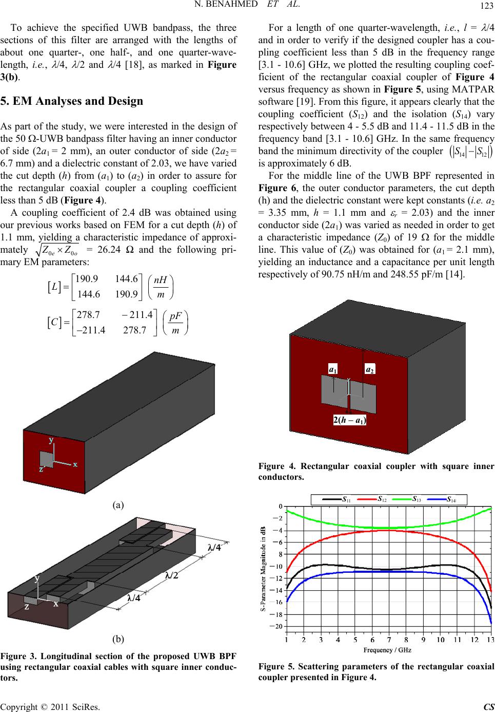 N. BENAHMED ET AL. 123 To achieve the specified UWB bandpass, the three sections of this filter are arranged with the lengths of about one quarter-, one half-, and one quarter-wave- length, i.e., /4, /2 and /4 [18], as marked in Figure 3(b). 5. EM Analyses and Design As part of the study, we were interested in the design of the 50 -UWB bandpass filter having an inner conductor of side (2a1 = 2 mm), an outer conductor of side (2a2 = 6.7 mm) and a dielectric constant of 2.03, we have varied the cut depth (h) from (a1) to (a2) in order to assure for the rectangular coaxial coupler a coupling coefficient less than 5 dB (Figure 4). A coupling coefficient of 2.4 dB was obtained using our previous works based on FEM for a cut depth (h) of 1.1 mm, yielding a characteristic impedance of approxi- mately 00eo Z Z = 26.24 Ω and the following pri- mary EM parameters: 190.9 144.6 144.6 190.9 nH Lm 278.7 211.4 211.4 278.7 pF Cm (a) (b) Figure 3. Longitudinal section of the proposed UWB BPF using rectangular coaxial cables with square inner conduc- tors. For a length of one quarter-wavelength, i.e., l = /4 and in order to verify if the designed coupler has a cou- pling coefficient less than 5 dB in the frequency range [3.1 - 10.6] GHz, we plotted the resulting coupling coef- ficient of the rectangular coaxial coupler of Figure 4 versus frequency as shown in Figure 5, using MATPAR software [19]. From this figure, it appears clearly that the coupling coefficient (S12) and the isolation (S14) vary respectively between 4 - 5.5 dB and 11.4 - 11.5 dB in the frequency band [3.1 - 10.6] GHz. In the same frequency band the minimum directivity of the coupler 14 12 SS is approximately 6 dB. For the middle line of the UWB BPF represented in Figure 6, the outer conductor parameters, the cut depth (h) and the dielectric constant were kept constants (i.e. a2 = 3.35 mm, h = 1.1 mm and r = 2.03) and the inner conductor side (2a1) was varied as needed in order to get a characteristic impedance (Z0) of 19 for the middle line. This value of (Z0) was obtained for (a1 = 2.1 mm), yielding an inductance and a capacitance per unit length respectively of 90.75 nH/m and 248.55 pF/m [14]. a 1 a 2 2(h – a 1 ) Figure 4. Rectangular coaxial coupler with square inner conductors. S 11 S 12 S 13 S 14 Figure 5. Scattering parameters of the rectangular coaxial coupler presented in Figure 4. Copyright © 2011 SciRes. CS 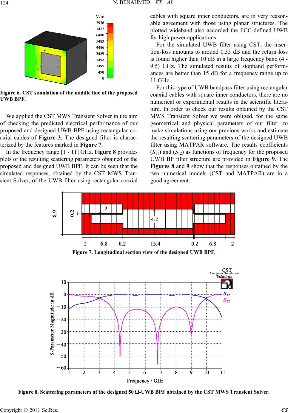 N. BENAHMED ET AL. Copyright © 2011 SciRes. CS 124 cables with square inner conductors, are in very reason- able agreement with those using planar structures. The plotted wideband also accorded the FCC-defined UWB for high power applications. V/m V/ m For the simulated UWB filter using CST, the inser- tion-loss amounts to around 0.35 dB and the return loss is found higher than 10 dB in a large frequency band (4 - 9.5) GHz. The simulated results of stopband perform- ances are better than 15 dB for a frequency range up to 11 GHz. For this type of UWB bandpass filter using rectangular coaxial cables with square inner conductors, there are no numerical or experimental results in the scientific litera- ture. In order to check our results obtained by the CST MWS Transient Solver we were obliged, for the same geometrical and physical parameters of our filter, to make simulations using our previous works and estimate the resulting scattering parameters of the designed UWB filter using MATPAR software. The results coefficients (S11) and (S12) as functions of frequency for the proposed UWB BP filter structure are provided in Figure 9. The Figures 8 and 9 show that the responses obtained by the two numerical models (CST and MATPAR) are in a good agreement. Figure 6. CST simulation of the middle line of the proposed UWB BPF. We applied the CST MWS Transient Solver in the aim of checking the predicted electrical performance of our proposed and designed UWB BPF using rectangular co- axial cables of Figure 3. The designed filter is charac- terized by the features marked in Figure 7. In the frequency range [1 - 11] GHz, Figure 8 provides plots of the resulting scattering parameters obtained of the proposed and designed UWB BPF. It can be seen that the simulated responses, obtained by the CST MWS Tran- sient Solver, of the UWB filter using rectangular coaxial Figure 7. Longitudinal section view of the designed UWB BPF. S 12 S 22 S 12 S 22 Figure 8. Scattering parameters of the designed 50 Ω-UWB BPF obtained by the CST MWS Transient Solver. 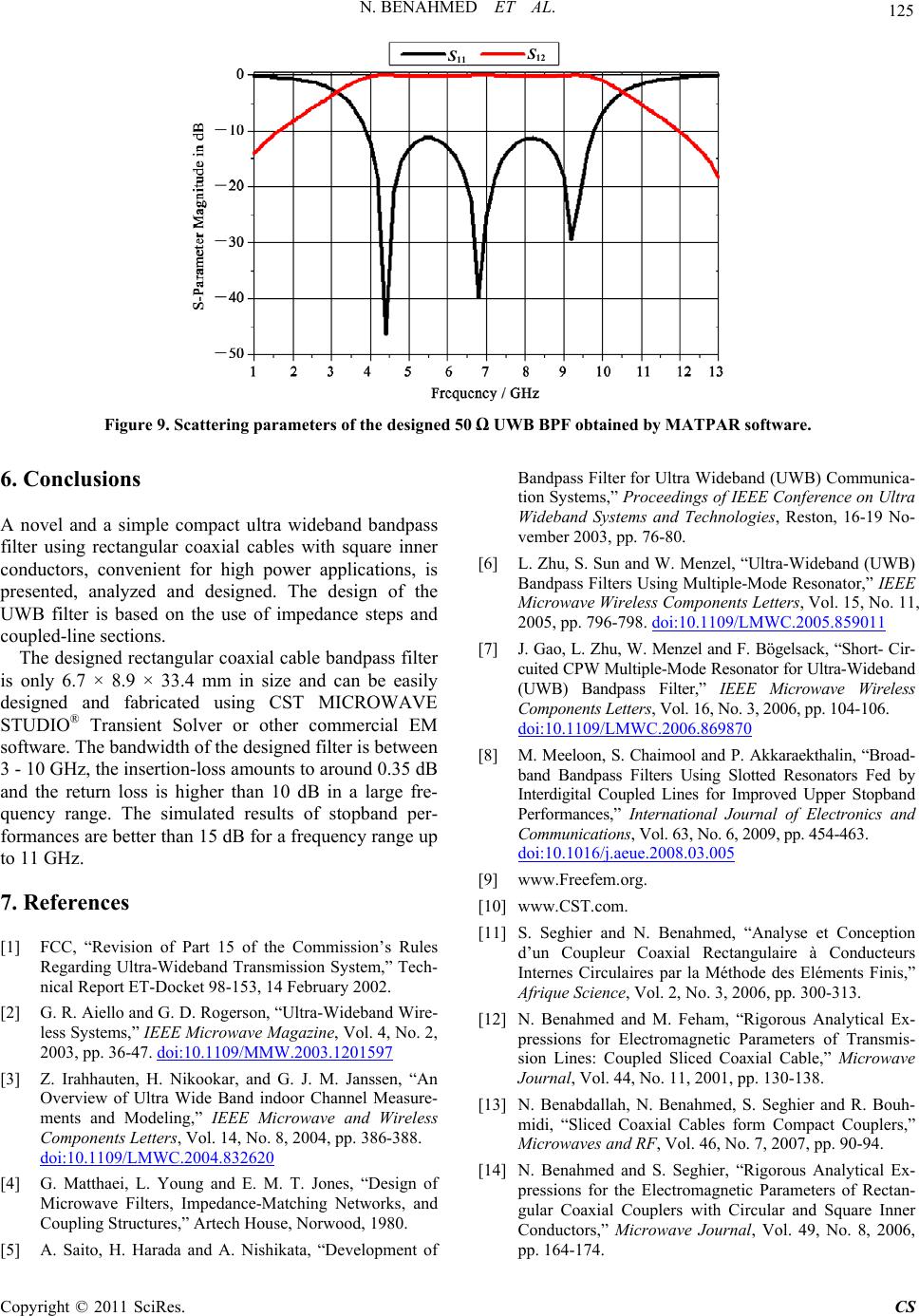 N. BENAHMED ET AL. 125 S 12 S 11 S 12 S 11 Figure 9. Scattering parameters of the designed 50 Ω UWB BPF obtained by MATPAR software. 6. Conclusions A novel and a simple compact ultra wideband bandpass filter using rectangular coaxial cables with square inner conductors, convenient for high power applications, is presented, analyzed and designed. The design of the UWB filter is based on the use of impedance steps and coupled-line sections. The designed rectangular coaxial cable bandpass filter is only 6.7 × 8.9 × 33.4 mm in size and can be easily designed and fabricated using CST MICROWAVE STUDIO® Transient Solver or other commercial EM software. The bandwidth of the designed filter is between 3 - 10 GHz, the insertion-loss amounts to around 0.35 dB and the return loss is higher than 10 dB in a large fre- quency range. The simulated results of stopband per- formances are better than 15 dB for a frequency range up to 11 GHz. 7. References [1] FCC, “Revision of Part 15 of the Commission’s Rules Regarding Ultra-Wideband Transmission System,” Tech- nical Report ET-Docket 98-153, 14 February 2002. [2] G. R. Aiello and G. D. Rogerson, “Ultra-Wideband Wire- less Systems,” IEEE Microwave Magazine, Vol. 4, No. 2, 2003, pp. 36-47. doi:10.1109/MMW.2003.1201597 [3] Z. Irahhauten, H. Nikookar, and G. J. M. Janssen, “An Overview of Ultra Wide Band indoor Channel Measure- ments and Modeling,” IEEE Microwave and Wireless Components Letters, Vol. 14, No. 8, 2004, pp. 386-388. doi:10.1109/LMWC.2004.832620 [4] G. Matthaei, L. Young and E. M. T. Jones, “Design of Microwave Filters, Impedance-Matching Networks, and Coupling Structures,” Artech House, Norwood, 1980. [5] A. Saito, H. Harada and A. Nishikata, “Development of Bandpass Filter for Ultra Wideband (UWB) Communica- tion Systems,” Proceedings of IEEE Conference on Ultra Wideband Systems and Technologies, Reston, 16-19 No- vember 2003, pp. 76-80. [6] L. Zhu, S. Sun and W. Menzel, “Ultra-Wideband (UWB) Bandpass Filters Using Multiple-Mode Resonator,” IEEE Microwave Wireless Components Letters, Vol. 15, No. 11, 2005, pp. 796-798. doi:10.1109/LMWC.2005.859011 [7] J. Gao, L. Zhu, W. Menzel and F. Bögelsack, “Short- Cir- cuited CPW Multiple-Mode Resonator for Ultra-Wideband (UWB) Bandpass Filter,” IEEE Microwave Wireless Components Letters, Vol. 16, No. 3, 2006, pp. 104-106. doi:10.1109/LMWC.2006.869870 [8] M. Meeloon, S. Chaimool and P. Akkaraekthalin, “Broad- band Bandpass Filters Using Slotted Resonators Fed by Interdigital Coupled Lines for Improved Upper Stopband Performances,” International Journal of Electronics and Communications, Vol. 63, No. 6, 2009, pp. 454-463. doi:10.1016/j.aeue.2008.03.005 [9] www.Freefem.org. [10] www.CST.com. [11] S. Seghier and N. Benahmed, “Analyse et Conception d’un Coupleur Coaxial Rectangulaire à Conducteurs Internes Circulaires par la Méthode des Eléments Finis,” Afrique Science, Vol. 2, No. 3, 2006, pp. 300-313. [12] N. Benahmed and M. Feham, “Rigorous Analytical Ex- pressions for Electromagnetic Parameters of Transmis- sion Lines: Coupled Sliced Coaxial Cable,” Microwave Journal, Vol. 44, No. 11, 2001, pp. 130-138. [13] N. Benabdallah, N. Benahmed, S. Seghier and R. Bouh- midi, “Sliced Coaxial Cables form Compact Couplers,” Microwaves and RF, Vol. 46, No. 7, 2007, pp. 90-94. [14] N. Benahmed and S. Seghier, “Rigorous Analytical Ex- pressions for the Electromagnetic Parameters of Rectan- gular Coaxial Couplers with Circular and Square Inner Conductors,” Microwave Journal, Vol. 49, No. 8, 2006, pp. 164-174. Copyright © 2011 SciRes. CS  126 N. BENAHMED ET AL. [15] N. Benahmed, M. Feham and M. Kameche, “Finite Ele- ment Analysis of Planar Couplers,” Applied Microwave & Wireless, Vol. 12, No. 10, 2000, pp. 28-38. [16] S. Seghier, N. Benabdallah, N. Benahmed, N. Benmo- stefa and R. Bouhmidi, “Accurate Closed-Form Formulas for the Electromagnetic Parameters of Squared Coaxial Lines,” International Journal of Electronics and Com- munications, Vol. 62, No. 5, 2008, pp. 395-400. [17] A. R. Djordjevic, M. B. Bazdar and T. K. Sarkan, “LIN- PAR for Windows: Matrix Parameters of Multiconductor Transmission Lines, Software and User’S Manual,” Artech House, London, 1999. [18] W. Menzel, L. Zhu, K. Wu and F. Bogelsack, “On the Design of Novel Compact Broadband Planar Filters,” IEEE Transactions on Microwave Theory and Tech- niques, Vol. 51, No. 2, 2003, pp. 364-370. doi:10.1109/TMTT.2002.807843 [19] A. R. Djordjevic, M. Bazdar, G. Vitosevic, T. Sarkar and R. F. harrington, “Scattering Parameters of Microwave Networks with Multiconductor Transmission Lines,” Artech House, London, 1990. Copyright © 2011 SciRes. CS |