

Paper Menu >>
Journal Menu >>
 Journal of Power and Energy Engineering, 2015, 3, 378-383 Published Online April 2015 in SciRes. http://www.scirp.org/journal/jpee http://dx.doi.org/10.4236/jpee.2015.34051 How to cite this paper: Bhatt, N., Liu, S.S., Podmore, R. and Croes , B. (2015) System Restoration Tools: System Restoration Navigator Integrated into EPRI Operator Training Simulator (SRN/OTS). Journal of Power and Energy Engineering, 3, 378- 383. http://dx.doi.org/10.4236/jpee.2015.34051 System Restoration Tools: System Restoration Navigator Integrated into EPRI Operator Training Simulator (SRN/OTS) Navin Bhatt1, Shanshan Liu1, Robin Podmore2, Bob Croes3 1Electric Power Research Institute, Palo Alto, USA 2Incremental Systems Corporation, Bellevue, USA 3Florida Reliability Coordinating Council, Inc., Tampa, USA Email: [email protected] Received Dec emb er 2014 Abstract System operators and planners develop and implement restoration plans based on off-line simu- lation studies, and accumulated experience and knowledge. One of the challenges in developing a restoration plan is to sift through numerous possible restoration scenarios and paths, in order to identify those that are technically feasible. When implementing a restoration plan in an on-line environment following a blackout, the operators need to adapt to the actual outage scenarios and available resources, and be constantly mindful of anticipated voltage and frequency excursions that must remain within system and equipment tolerances. In recognition of these challenges, EPRI has developed System Restoration Navigator (SRN), to provide decision support to system restoration planning and operations engineers in developing, evaluating and revising system res- toration strategies, guidelines, plans and step-by-step procedures. During 2013-2014, EPRI de- veloped SRN version 3.0, which is designed to facilitate its integration into a commercial operator training simulator (OTS) (AKA a dispatch training simulator, DTS). The integration of SRN 3.0 with an OTS allows operators to obtain experience in simulating, developing, experimenting with and revising system restoration plans, and to address related regulatory standards. The integration expands the usability of SRN 3.0 by providing the OTS platform for training purposes and for the purpose of interfacing SRN 3.0 with operational power system models to be able to explore near real time application of SRN 3.0. This 2013-2014 development work also included the integration of SRN 3.0 into EPRI OTS, and its application on the Florida Reliability Coordinating Council (FRCC) power system. A detailed account of development of SRN 3.0, its integration into EPRI OTS and its application to FRCC system is presented in this paper. Keywords System Restoration, Restoration Paths and Sequences, Operator Training Simulator 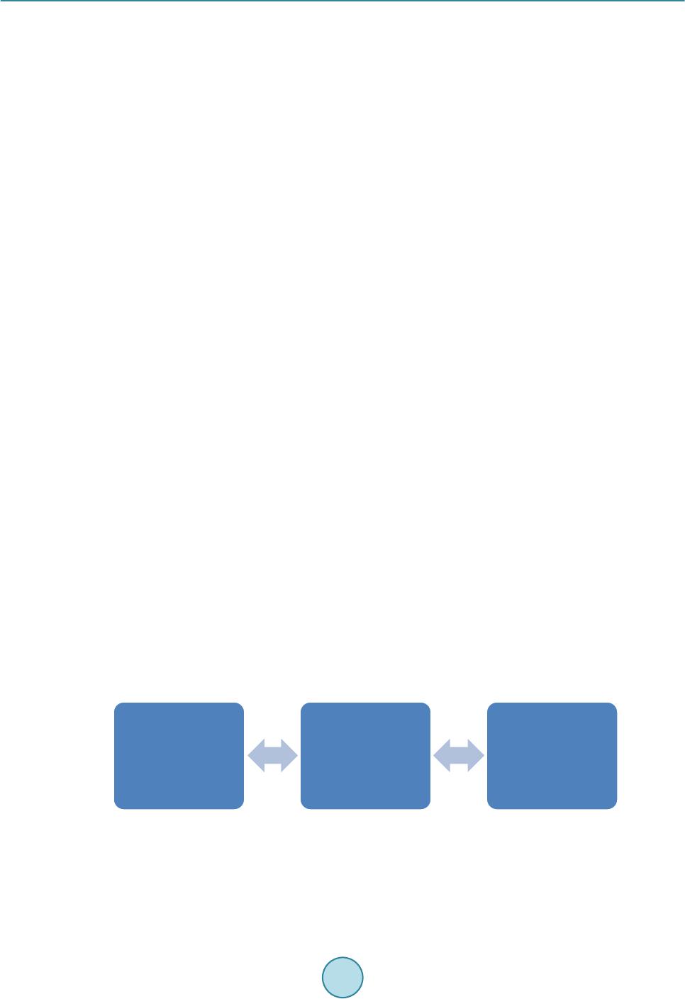 N. Bhatt et al. 379 1. Introduction 1.1. Technology Need System operators and planners develop and implement restoration plans based on off-line simulation studies, and accumulated experience and knowledge. One of the challenges in developing a restoration plan is to sift through numerous possible restoration scenarios and paths, in order to identify those that are technically feasible. And, when implementing a restoration plan in an on-line environment following a blackout, the operators need to adapt to the actual outage scenarios and available resources, and be constantly mindful of anticipated voltage and frequency excursions that must remain within system and equipment tolerances. In recognition of these challenges, EPRI initiated R & D in 2008 to develop system restoration decision support tools and has devel- oped two tools to provide decision support for these activities, namely System Restoration Navigator (SRN) and Optimal Blackstart Capability (OBC). The subject of this paper is the SRN tool. 1.2. EPRI System Restoration Navigator (SRN) Tool During 2010-2011, EPRI developed System Restoration Navigator (SRN) as a decision support tool for opera- tors and planners to develop, evaluate and revise system restoration strategies, guidelines, plans and step-by-step procedures [1]. SRN version 2.0, published in 2011 [2], is designed to be used as an off-line study tool using PSS/E power flow data as input. SRN 2.0 is meant to be used primarily by restoration planners to develop, vali- date and update restoration plans. It can be used to run power flow snapshots that represent various system res- toration scenarios. A large power system could involve hundreds or even thousands of restoration scenarios, making the use of SRN 2.0 somewhat challenging. Other limitations of SRN 2.0 include inabilities to accept node-breaker power system models and real-time EMS data. Therefore, SRN 2.0 cannot be used for near real- time or near mission-critical applications. More recently, system operators have been using operator training simulators (OTSs) to develop and validate system restoration plans [3]. Therefore, during 2013-2014, EPRI developed System Restoration Navigator for Operator Training Simulators, referred to as SRN 3.0. The SRN 3.0 software tool is designed to facilitate its in- tegration into a commercial operator training simulator (OTS). The integration of SRN 3.0 with an OTS allows operators to obtain experience in simulating, developing, experimenting with and revising system restoration plans. The integration expands the usability of SRN 3.0 by providing the OTS platform for training purposes and for the purpose of interfacing SRN 3.0 with operational power system models. This 2013-2014 development work also included the integration of SRN 3.0 into EPRI OTS, and its applica- tion on the Florida Reliability Coordinating Council (FRCC) power system. A detailed account of development of SRN 3.0 and its integration into EPRI OTS is presented in this paper. 2. SRN 3.0 Software Development, Design and Functionality 2.1. Components of SRN 3.0 Software Package As shown in the figure below, SRN 3.0 software package consists of the following modules: 1) SRN 3.0; and 2) Application Programming Interface (API). The main objective of SRN is to find an ideal path or sequence from a given location, typically a blackstart generator, in order to crank non-black start (NBS) generating units or to pick up loads for the purpose of con- trolling voltage and frequency and meeting unit limits. SRN provides key information (e.g. line charging) re- garding the identified path, in order to help in deciding proper sequence during the various stages of restoring a system from a blackout. 1. SRN 3.0 •(Core component. Designed to help in devleoping, evaluating, practicing and implementing restoration plans) 2. API •(Designed to provide guidance in integrating the SRN Module into an OTS) OTS •(Use the API as reference to integrate SRN 3.0 into the OTS)  N. Bhatt et al. 380 The SRN 3.0 generates a restoration plan under the users’ guidance iteratively. The step by step evolution of the restoration plan can be displayed in substation one-line diagrams and transmission overview diagrams. As components are energized, they are colorized so that the extent of the electrical islands is apparent to the user. The SRN 3.0 determines a sequence of efficient circuit breaker operations to energize various system compo- nents. It finds a feasible sequence, which has shortest estimated time duration to crank non-black start (NBS) generating units and to pick up loads for the purpose of controlling voltage and frequency and meeting unit minimum limits. Once SRN 3.0 module is integrated with an operator training simulator, its usefulness is enhanced signifi- cantly. The OTS power system map, the underlying power system model and the station one-line displays can be used to show the impact of the breaker operations produced by SRN 3.0. The OTS AGC function can be used to maintain frequency in islands as load is added to the system. The AGC function can also be used to ensure that the generators observe their minimum and maximum operating limits, and ramp rates. 2.2. Integration of SRN 3.0 Module into an OTS SRN 3.0 has been developed for integration with Operator Training Simulators of multiple vendors. SRN 3.0 can be integrated with an existing operator training simulator using the API software as the reference. Once the integration is complete, SRN 3.0 can establish a system restoration plan following a complete or partial outage. The plan can then be displayed on OTS maps and one-line diagrams. Users can control the restoration process interactively by selecting the sequence of generating units and loads that are organized. Commercial Operator Training Simulators typically consist of two subsystems: • A Power System Model that simulates the long term dynamics of the power system as a base. • A Control Center Model that simulates the control center software and hardware including SCADA, AGC and possibly other network applications such as State Estimator and Contingency Analysis. A Control Cen- ter Model may be an exact replica of an existing Control Center or it may be software that emulates the op- eration of a variety of control centers. The instructor interacts with the Power System Model and can create all sorts of events to simulate normal as well as emergency events such as hurricanes, tornados, ice storms, cyber-attacks, physical attacks etc. The in- structor also plays the roles of neighboring system operators, Reliability Coordinators and field crews. The system operator works with the Control Center Model, and monitors and controls the simulated power system through SCADA, AGC and network application displays. 2.3. SRN 3.0 Functionality SRN 3.0 has been designed and developed to provide system operators and engineers with a new tool that can significantly improve the quality, efficiency and robustness of system restoration analyses. SRN 3.0 is scalable to handle practical large systems and operational models that include node-breaker details. In a similar way to how automobile GPS navigation software provides someone that is in unfamiliar territory or complicated road conditions with very helpful step by step directions, the EPRI SRN 3.0 can provide an en- gineer or system operator that is unfamiliar with a power system or a system condition with prioritized feasible options and specific step by step directions for implementing the selected options. SRN 3.0 has been designed to help a student or an engineer to emulate the thought processes and control ac- tions of an expert system operator. Further, in a similar way to how automobile software provides real time updates of the driver’s location on geographic maps to assist with overall orientation, transmission system overviews provide the engineer or sys- tem operator with real-time orientation of the current state of the power system. The step by step evolution of the restoration plan can be displayed in substation and transmission overview diagrams. As components are energized, they are colorized so that the extent of the electrical islands is apparent to the user. The transmission overviews show the extent of electrical islands along with bus voltages and line flows. With SRN 3.0, engineers and operators can focus on studying the benefits of different restoration methods. SRN 3.0 takes care of the error prone routine switching operations efficiently and reliably. As an example, iso- lating and building a path to restore power from gas turbines to a shutdown nuclear power plant might take around 10 to 20 minutes in a real-time simulation. The system operator has to carefully open all the required circuit breakers to clear the energization path. If one breaker is inadvertently left closed the island will blackout  N. Bhatt et al. 381 as it tries to pick up too much load. With SRN 3.0, the correct sequence of breaker operations can be computed reliably and accurately and implemented in the simulator in around 10 seconds. The increase in efficiency is such that a single engineer can simulate the restoration process for a reliability coordinator in a day instead of weeks. For example, the Principle Investigator of this software development project used SRN 3.0 to restore the FRCC system from blackstart so that 30% of generation capacity was on-line in the six electrical islands that have blackstart capability and running above minimum load. SRN 3.0 is adaptable to handle the different Bottom Up and Top Down restoration methods that are currently being used to develop restoration plans and train system operators [4]. It handles the three variants of the Bottom Up method including: • Multiple Island Method of Restoration. • Core Island Method of Restoration. • Backbone Island Method of Restoration. It is also adaptable to handling the Top Down Method where a TOP interconnects with a neighboring system in order to expedite the restoration. With SRN 3.0, Reliability Coordinators (RCs) and Transmission Operators (TOPs) can proactively demon- strate that they have met the NERC EOP 006 and EOP 005 standards through accurate, verifiable, repeatable and documented simulations. This is in contrast to an approach in which an RC engineer or operator passively reads and reviews the restoration plan documents for different TOPs and looks for inconsistencies based upon his or her own experience and judgment. 3. SRN 3.0 Integration into EPRI OTS 3.1. EPRI OTS EPRI OTS, referred to here as OTS-PowerSimulator, is an easy to use simulator, which allows operators to ob- tain experience in handling emergency and abnormal operation conditions without the risks of dealing with a live power system. OTS-PowerSimulator is driven by a highly realistic long term dynamic model that simulates power system behavior under a wide range of abnormal conditions that includes thermal system overloads, vol- tage collapse, off nominal frequency, Ferranti voltage rise, system islands, large angle variations and cold load pickup. Events can be introduced so that the operator is faced with a challenging operating problem such as se- vere overloads or loss of load and generation. The simulator responds in real-time with flows and voltages up- dated every few seconds. The operator controls the simulator using a set of transmission and substation one-line diagram displays that can be laid out to mimic the displays that he may use as part of his EMS or SCADA sys- tem. OTS-PowerSimulator has been built by a cooperative effort from EPRI, Incremental Systems Corporation and Power Data Corporation. Every time the Power System Model calculates a new set of analog and status values, these are used to update the System Map and substation displays. A set of OTS-PowerSimulator Control dis- plays can be used for initializing the base case, activating the simulator events, starting and stopping the simula- tion, and monitoring the power system conditions. The PowerSimulator one-line and tabular displays can be used to simulate actions of power plant operators, substation operators and neighboring utility Operators. OTS-PowerSimulator is the leading product for ensuring that NERC certified system operators obtain their NERC mandated 32 hours of annual training in Emergency Operations along with their simulator based contin- uing education hours to maintain their operator certification. OTS-PowerSimulator has been used with generic system models to train operators at more than 140 Transmission Operators, Balancing Authorities and Reliabili- ty Coordinators. OTS-PowerSimulator has been used with system specific models to train operators at more than 40 Transmission Operators, Balancing Authorities and Reliability Coordinators. 3.2. SRN 3.0 Integration with OTS-PowerS imula tor The integration of SRN 3.0 with OTS-PowerSimulator allows operators to obtain experience in simulating, de- veloping, experimenting with and revising system restoration plans. The integration expands the capability of the EPRI OTS from the system restoration viewpoint, and expands the usability of the SRN 3.0 method by pro- viding the OTS platform for training purposes and for the purpose of interfacing SRN 3.0 with operational pow- er system models.  N. Bhatt et al. 382 The Figure below shows how SRN 3.0 has been integrated into OTS as well as into the PACE infrastructure. The SRN 3.0 code uses the OPEN PA (POWER APPs) Java libraries that have been developed by IncSys and PowerData. 3.3. Possible Industry Application of SRN 3.0 SRN 3.0 can be used to address the following NERC standards: 1) EOP-005-2—System Restoration from Blackstart Resources; and 2) EOP-006-2—System Restoration Coordination. With SRN 3.0, Reliability Coor- dinators (RCs) and Transmission Operators (TOPs) can proactively demonstrate that they have met these stan- dards through accurate, verifiable, repeatable and documented simulations. This is in contrast to an approach in which an RC engineer or operator passively reads and reviews the restoration plan documents for different TOPs and looks for inconsistencies based upon his or her own experience and judgment. 3.4. Application of SRN 3.0 for FRCC System Restoration Drill SRN 3.0 was used to create a six-island energized base case to support the FRCC wide restoration drills that were conducted on September 30th, 2014 starting 1000 AM through 300 PM Eastern time. The base case for this drill was created as follows. A fully energized base case of the FRCC system and the Eastern Interconnec- tion was used as the starting point. The ties between FRCC and Southern Company were opened to create two islands. The FRCC system island was then blacked out by opening all generator breakers. Restoration from an FRCC blackout requires the transmission operators to disconnect from each other and start up individual elec- trical islands. In this scenario, six “electrical islands” across the FRCC system were created. During the drill, each of 16 Transmission Operators logged in remotely to the web-based simulator. The operators represented a variety of utility types, including investor-owned, municipalities and co-ops. Everyone was also connected using a hotline—a phone line that is kept open among all members of the FRCC at all times in case of emergency. Starting with the designated FRCC black start units, SRN 3.0 was used to very efficiently create six islands with approximately 30% of the generation on-line and with those generators operating above their minimum loads. As a result of this base case, the FRCC system operators were able to address a range of restoration objec- tives that would not normally be accomplished in a five hour restoration drill including the following: • Perform Transmission & Generation assessment and report to Reliability Coordinator (RC). • Verify off site power to nuclear plants. • Identify island boundaries and report to RC. • Open de-energized tie lines and implement Transmission Operator (TOP) restoration plan. • Resynchronize islands to the Eastern Interconnection and restore from the Eastern Interconnection. • Identify the highest loaded generator in island and assess operating reserves. • Prepare the TOP resynchronization plan. • Once the TOP island is stable, resynchronize to adjacent stable TOP islands under the direction of the FRCC RC. • Provide start-up power to non-black start gene ra to rs. • Re-synchronize all electrical islands.  N. Bhatt et al. 383 The total time to build the base case was around 9 hours. SRN 3.0 was used in the following manner: • Providing off-site emergency power starting from the black start units to the nuclear plants. • Energizing cranking paths to and synchronizing non-black start units. • Locating and energizing loads close to energized transmission and generators. The AGC program for each Balancing Authority was activated from the outset with all non-black start units placed in LFC mode. Blocks of load were energized manually by following the rule that the load block should not exceed 5% of the on-line capacity in the island. Frequency deviations with added blocks of load generally stayed above 59.5 HZ. The QuickMaps tool was used to build transmission overview for each Transmission Operator. The Trans- mission Overviews were used to maintain situational awareness of system voltages and transmission line load- ing. De-energized lines are shown as white. Additional transmission paths were energized and loops were closed manually in order to maintain line loading and voltages within their operating limits. As a result of SRN 3.0 be- ing used, the base case was built without any operating errors involving the addition of too much load due to in- correct isolation. Based on the feedback provided by Bob Croes, FRCC Manager of RC Operations and Oversight, the IncSys, PowerData and EPRI tools used in the FRCC drill not only create the conditions that would exist during restora- tion, but the tools also show the operators what would happen based on the actions they take to fix the problem. FRCC engineers and operators simulated conditions approximately 10 - 12 hours after a complete blackout of Florida and the EPRI System Restoration Navigator 3.0 was key so that FRCC could create the system initial conditions with a reasonable amount of engineering time. FRCC and the 16 TOPs were quite satisfied with the drill as they were able to accomplish all the drill objectives. References [1] (2010) Development of Power System Restoration Tool Based on Generic Restoration Milestones. EPRI, Palo Alto. [2] (2011) System Restoration Navigator (SRN) Software Version 2.0. EPRI, Palo Alto. [3] Liu, S.S., Hou, Y.H., Liu, C.-C. and Podmore, R. (2014) Tools and Challenges for Smart Grid Restoration—The Heal- ing Touch. IEEE Power and Energy Magazine, Jan/Feb, 55-64. [4] PJM Fundamentals of Transmission Operations (FOTO) Course. |