

Paper Menu >>
Journal Menu >>
 Journal of Power and Energy Engineering, 2015, 3, 269-273 Published Online April 2015 in SciRes. http://ww w.scirp.org/journal/jpee http://dx.doi.org/10.4236/jpee.2015.34036 How to cite this paper: Lai, W.-C. and Wu, C.-L. (2015) Effect of Metal and Magnetic Slab on Radiation Characteristics of Monopole Antenna. Journal of Power and Energy Engineering, 3, 269-273. http://dx.doi.org/10.4236/jpee.2015.34036 Effect of Metal and Magnetic Slab on Radiation Characteristics of Monopole Antenna Wen-Cheng Lai, Ching-Ling Wu Department of Electronic Engineering, Ming Chi University of Technology, New Taipei, Taiwan Email: wjlay @ma il. mcut .edu .t w, [email protected] Received Dec emb er 2014 Abstract The effect of metal and magnetic slab on the radiation characteristic of monopole antenna is stu- died in this paper. The presence of metal slab ch an ge s the antenna r adiation patte rn and it also increases the gain up to 4.6 dB. The radiation charac te ris tic of monopole antenna is determined by the separation distance between planar monopole and metal slab. In addition, magnetic slab also change s the antenna radia tion p att ern and it also increases the gain up to 3 dB. Metal slab makes antenna generate reflection, but magnetic slab makes antenna generate refraction is their differ- ence. As to the application sl ab, the initial pattern of the antenna without materials was omnidi- rectional. However, when the materials were added, its pattern would change, making the antenna to hav e other usages and transition effect. They will influence electromagnetic in power systems. Keywords Metal Slab, Magnetic Slab, Monopole Antenna, Radiation Pattern, Power Systems 1. Introduction With the antenna’s pattern/frequency reconfigurability, the noise sources or intentional interference in a hostile environment are suppressed or alleviated. The antennas of this sort have been reported, e.g. [1]-[7]. On the other hand, the single turn square spiral microstrip antenna with both reconfigurable radiation pattern and frequency was demonstrated in [8]. More details on the reconfigurable antenna designs and applications can be found in [9]. In this paper, we introduce the effect of metal and magnetic slabs on the return loss, radiation patte rn and gain of monopole antenna. In this study, a monopole antenna with an operation frequency of 2.4 GHz is em- ployed to explore the variatio n of radiation characteristics due to the presence of two slabs placed at different distances from the monopole antenna. 2. Experimental Setup and Met ho d 2.1. Experimental Setup First, in Figure 1 shows that the setup of monopole antenna and either metal or magnetic slab. A metal or mag- 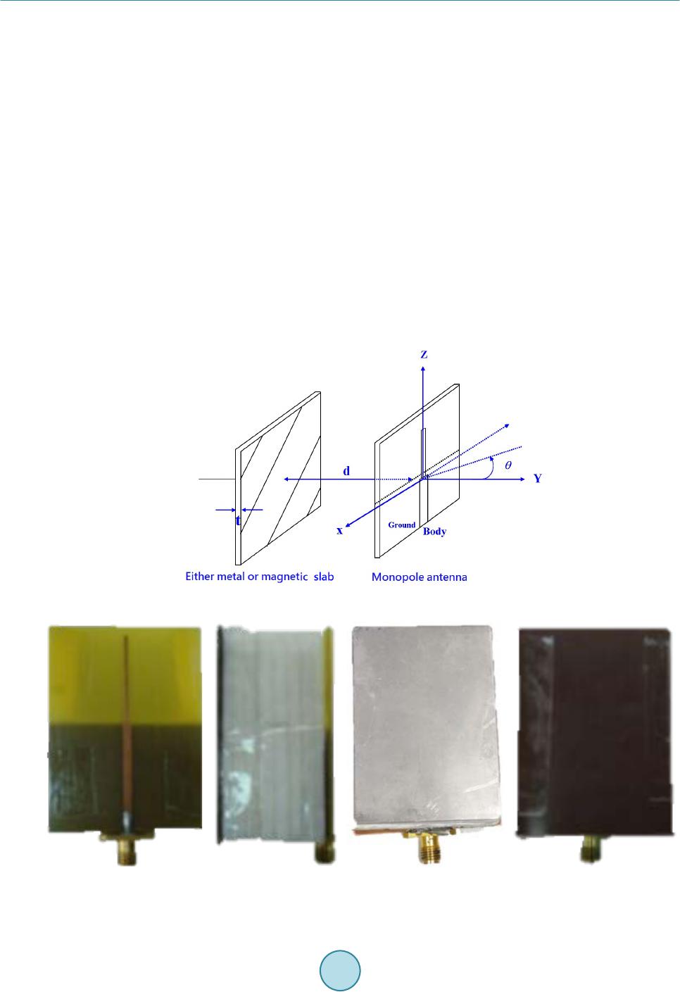 W.-C. Lai, C.-L. Wu 270 netic slab is placed in parallel to the planar monopole antenna fed with microstrip. The distance between two parallel plates is d, the thickness of slab is t and θ is the angle. 2.2. Experimental Method The photograph of top, side, and bottom views of the fabricated antenna are shown in Fig ur es 2(a)-(d), respec- tively. A styrofoam board is employed to control the distance d between the slab and the monopole antenna. Since the styrofoam board is thin, a stack of foam board will be used to change the distance d little by little (about 3 mm) with every piece added. Notice that the styrofoam board is fixed through scotch tape and the metal or magnetic slab is placed on the ground plane side of the monopole antenna. The thickness of metal slab is 0.9 mm. The thickness of magnetic slab is 1 mm. 3. Experimental Res ult s 3.1. Return Loss of the Monopole Antenna as a Function of the S pac ing The measured return loss against different spacing is shown in Fig ure 3(a), Figure 3(b) [10]. 3.2. Variation of Pattern and Gain as a Function of d Figure 4(a) and Figure 4(b) show the simulated and measured radiation patterns at the E-planes at the resonant Figure 1. Schematic diagram of monopole antenna and either metal or magnetic slab. (a) (b) (c) (d) Figure 2. The (a) top, (b) side, (c) metal slab with bottom and (d) magnetic slab with bottom view of antenna.  W.-C. Lai, C.-L. Wu 271 (a) (b) Figure 3. The return loss of (a) metal slab and (b) magnetic slab of the monopole antenna as a function of the spacing. (a) (b) Figure 4. Simulated and measured pat terns as a function of distance d between the (a) metal slab and (b) magnetic slab and the ground plane of monopole antenna.  W.-C. Lai, C.-L. Wu 272 (a) (b) Figure 5. Measured gains as a function of distance d between (a) metal slab and (b) magnetic slab and the ground plane of monopole antenna. frequency (2.4 GHz). It is shown that the measured data are in excellent agreement with the simulated one. In Figure 4(a), a metal slab with thickness of 0.9 mm is employed in the experiment. When metal slab is placed on the ground side of the monopole antenna, the pattern changes significantly as the distance d increased. The E-plane radiation pattern becomes directional compared to the one of the classical monopole at θ = 0˚. Again, in Figure 4(b) [10], a magnetic slab with thickness of 1 mm is employed in the experiment. When magnetic slab is placed on the ground side of the monopole antenna, the pattern also changes. The E -plane radiation pattern be- comes directional compared to the one of the classical monopole [11] at θ = 0˚, 180˚. The pattern of the antenna is omnidirectional when the magnetic slab is absent. The pattern changes gradually as the magnetic slab moves farther from the grounding plate of the antenna. 3.3. Effect of d on the Gain of the Ground Shielding Figure 5 shows the gain variation of antenna system as a function of d for the metal or magnetic slab. In the metal slab case as Figure 5(a), the antenna gain always less than without slab of monopole antenna at θ = 180˚. When d = 10.5 mm, the antenna gain start large than without slab of monopole antenna at θ = 0˚. When d = 35.86 mm, it can increase the antenna gain to 4.6 dB at θ = 0˚. In the magnetic slab case as Figure 5(b) [10], the gain is less than 0 dB as d < 15 mm. As d > 20 mm, the magnetic slab acts as a reflector so that appreciable gain is obtained. On the other hand, Figure 5 shows the antenna gain as a function of d for different values of mag- netic slab thickness at θ = 180˚. The antenna has appreciable gain for 10 mm < d < 30 mm. The optimal gain occurs when 14 mm < d < 16 mm. The max. gain 3 dB holds for a large range of d. 4. Conclusion A planar monopole antenna with reconfigurable radiation pattern is presented. It is found that, the presence of metal slab with thickness of 0.9 mm will yield reflection e ffects, which can increase the antenna gain to 4.6 dB at θ = 0˚ and produce desirable radiation pattern. In other hand, the prese nce of magnetic slab with thickness of 1 mm will yield refraction or reflection effects, which can increase the antenna gain to 3 dB at θ = 180˚ and produce desirable radiation pattern. The measured results are in good agreement with the simulated results, as shown in Fig ure 4. So we can see that metal slab better than magnetic slab in this verification. It seems that we placed items inadvertently in the general household, but it inducing electromagnetic will influence the power system [12]. References [1] Anagnostou, D., Zheng, G. , Chryssomallis, M., Lyke, J., Ponchak, G., Papapolymerou, J. and Christodoulou, C. (2003)  W.-C. Lai, C.-L. Wu 273 Design, F abri cation, and Measurements of an RF-MEMS-Based Self-Similar Reconfigurable Antenna. Proceedings of the 2003 IEEE International Symposium on Circuits and Systems, 54, 422-43 2. [2] Huff, G.H. and Bernhard, J.T. (2006) Integration of Packaged RF MEMS Switches with Radiation Pattern Reconfi- gurable Square Spiral Microstrip Antennas. IEEE Transactions on Antennas and Propagation, 54, 464-469. http://dx.doi.org/10.1109/TAP.2005.863409 [3] Grau, A., Romeu, J., Lee, M.-J., Blanch, S., Jofre, L. and Flaviis, F.D. (2010) A Dual-Linearl y-Polarized MEMS-Re- configurable Antenna for Narrowband MIMO Communication Systems. IEEE Transactions on Antennas and Propa- gation, 58, 4-17. http://dx.doi.org/10.1109/TAP.2009.2036197 [4] Nikolaou, S., Bairavasubramanian, R., Lugo, C., Carrasquillo, I., Thompson, D., Ponchak, G., Papapolymerou, J. and Tentzeris, M. (2006) Pattern and Frequency Reconfigurable Annular Slot Antenna Using PIN D io des . IEEE Transac- tions on Antennas and Propagation, 54, 439 -448. http://dx.doi.org/10.1109/TAP.2005.863398 [5] Jin, N., Yang, F. and Rahmat-Samii, Y. (2004) A Novel Reconfigurable Patch Antenna with Both Frequency and P ola- rization Diversities for Wireless Communications. Proceed ings of IEEE Antennas and Propagation Society Interna- tional Symposium, 2, 1796-1799. [6] Ch en, R.-H. and Row, J.S. (20 08) Single-Fed Microstrip Patch Antenna with Switchable Polarization. IEEE Transac- tions on Antennas and Propagation, 56, 922 -926. http://dx.doi.org/10.1109/TAP.2008.919211 [7] Aissat, H., Cirio, L. , Grzeskowiak, M., Laheurte, J.-M. and Picon, O. (2006) Reconfigurable Circularly Polarized An- tenna for Short-Range Communication Systems. IEEE Transactions on Microwave Theory and Techniques, 54, 2856- 2863. http://dx.doi.org/10.1109/TMTT.2006.875454 [8] Huff, G.H., Feng, J., Zhang, S. and Bernhard, J.T. (2003) A Novel Radiation Pattern and Frequency Reconfigurable Single Turn Square Microstrip Spiral Antenna. IEEE Microwave and Wireless Components Letters, 13, 57-59. http://dx.doi.org/10.1109/LMWC.2003.808714 [9] Bernhard, J.T. (2007) Reconfigurable Antenna: Synthesis Lectures on Antennas. Mor gan & Claypool. [10] Lai, W.-C., Miao, D.-L. and Hsue, C.-W. (2009) Effect of Magnetic Layer on Radiation Characteristics of Monopole Antenna. 4th International Conference on Electromagnetic Near-Field Characterization and Imaging (ICONIC 2009), Taipei, 255-258 . [11] Balani s, C.A. (1997 ) Antenna Theory, Analysis and Design. 2nd Edition, Wiley, New York. [12] Kong, S., Kim, J., Bae, B., Kim, J.J., Kim, S. and Kim, J. (201 4) Electromagnetic Radiated Emissions from a Wireless Power Transfer System Using a Resonant Magnetic Field Coupling. International Symposium on Electromagnetic Compatibility, Tokyo, Ma y, 406-409. http://dx.doi.org/10.1109/WPT.2014.6839613 |