

Paper Menu >>
Journal Menu >>
 Materials Sciences and Applicatio ns, 2011, 2, 684-691 doi:10.4236/msa.2011.26094 Published Online June 2011 (http://www.SciRP.org/journal/msa) Copyright © 2011 SciRes. MSA Using Kaolinitic Clay for Preparation of a Hydrotalcite-Like Compound Khaled Hosni*, Ezzeddine Srasra Centre National des recherches en Sciences des Matériaux, Pôle technologique de Borj Cedria, Nabeul, Tunisia. Email: [email protected] Received December 24th, 2010; revised March 21st, 2011; accepted May 18th, 2011. ABSTRACT In this study, Mg-Al-CO3 hydrotalcite was synthesized from a kaolinite as natural source aluminium using two simple methods. The first method uses the kaolinite in natural solid state, the second method use the filtrate of the kaolinite after dissolution by acidic solutions. The structure of the materials was characterized by X-ray diffraction, Fourier transform infrared spectroscopy, differential scanning calorimetry (DSC) and Brunauer, Emmett, and Teller (BET) measurements. Keywords: Hydrotalcite, Kaolinite, Layered Compound, XRD, Memory Effect 1. Introduction A wide range of compositions are possible for synthetic hydrotalcites based on the general formula II IIIy+n [ML(OH)][X][H O] 3- PO 1-yy2y/n2z , where MII and MIII are the divalent and trivalent cations in the octahedral posi- tions within the hydroxide layers. The value y can have a range between 0.17 and 0.33, while Xn– is an interlayer anion with a negative charge n– [1,2], and z is the number of water molecules. Many anions or anionic complexes, both organic and inorganic, can be incorporated into the hydrotalcite structure. The hydrotalcite can be abbrevi- ated as [MII – MIII – X], where, MII = Mg2+, Zn2+, Cu2+, Ca2+, Mn2+; MIII = Al3+, Cr3+, Fe3+, ; and Xn– = Cl–, NO3–, CO3–, , etc. 4 Hydrotalcite-like compounds, also called layered dou- ble hydroxides (LDHs), have received considerable at- tention in recent years owing to their layered structure and high anion-exchange capacity [3], which makes them potential materials for technical applications in various domains [4]. These materials have been investigated as solid ionic conductors [5] and sensors [6]. Layered dou- ble-metal hydroxides are, or may be used as, catalysts [4,7], photo-catalysts, catalyst supports [8], adsorbents [9,10], anion exchangers [11], medicines [12,13] and bonding materials. The reason for the potential applica- tion of hydrotalcites as catalysts rests with their ability to make mixed metal oxides at the atomic level, rather than the particle level. Such mixed metal oxides are formed through the thermal decomposition of the hydrotalcite [14]. Also, LDH materials have been extensively studied in terms of their thermal evolution [15,16], textural properties [16], and the formation of nanosized metal particles [17] as well as for environmental purposes [18]. The present study reports simplified method to synthe- size the carbonate forms of layered double hydroxides from a natural source of trivalent cations. Mg-Al-CO3 hydrotalcite-like layered compounds have been synthe- sized with Mg/Al ratios of 3 by a mechanochemical method using kaolinite in solid state and by coprecipita- tion using the under product of the acidic dissolution of the kaolinite. 2. Experimental 2.1. Material Preparation The Mg-Al-CO3 hydrotalcite-like layered compounds has been synthesized by two simple methods using kaolinite as a natural source of trivalent cations and an aqueous solution of Na2CO3 as the precipitant. Method 1 The sample was synthesized by crushing kaolinite with the magnesium nitrate hexahydrate (their amounts were so as to have the desired Mg2+/Al3+ molar ratio), fol- lowed by heating at 500˚C for 4 hours. The product ob- tained was dispersed under constant stirring in an aque- ous solution containing Na2CO3 (100 mL). The pH of the dispersion was maintained constant at 10 ± 0.1 by adding NaOH or HNO3 when necessary. The slurry was subse-  Using Kaolinitic Clay for Preparation of a Hydrotalcite-Like Compound685 quently agitated at room temperature for 24 h, and then aged at 150˚C for 24 h. The resulting products were col- lected by centrifugal separation and washed thoroughly with deionised water to eliminate excess Na+ followed by drying overnight at room temperature. The samples were identified as [Ksd3P10-T150], where Ksd represents the trivalent cation source (kaolinite) used to prepare the materials and “sd” represents the solid state. For example, Ksd3P10-T150 stands for the product prepared with kaolinite in solid state, a Mg/Al ratio of 3, an aging temperature of 150˚C, and a pH of synthesis of 10. Method 2 The sample was synthesized using as aqueous solution of Na2CO3 as precipitant. The solutions containing Mg(NO3)2·6H2O and Al3+, cation resulting from dissolu- tion of the purified kaolinite by acidic attack, (their con- centration varied so as to have the Mg/Al molar ratio of 3) were added dropwise to the aqueous solutions of Na2CO3 with vigorous stirring. The pH of the dispersion was maintained constant at 10 ± 0.1 by adding NaOH (10%). The slurry was subsequently agitated at room tempera- ture for tree day. The resulting products were collected by centrifugal separation and washed thoroughly with deionised water to eliminate excess Na+ followed by drying overnight at room temperature. The samples were identified as [Kliq3P10], where Kliq represents the trivalent cation source (kaolinite) used to prepare the materials and “liq” represents its liquid state. For example, Kliq3P10 stands for the product prepared with kaolinite in liquid state, an Mg/Al ratio of 3 and a pH of synthesis of 10. 2.2. Characterization of Materials The dried precipitates were characterized by X-ray dif- fraction (XRD) in order to determine the species present and their degree of crystallinity. Diffractograms were obtained by using a ‘PANalytical X’Pert HighScore Plus’ diffractometer using monochromated CuKα radiation. Nitrogen adsorption measurements were performed at –196˚C with an Autosorb-1 unit (Quantachrome, USA) for the determination of sample textural properties using the multipoint Brunaner-Emmet-Teller (BET) method. The samples were out gassed at 120˚C under a vacuum at 10–3 mmHg for 3.5 h. Fourier-transformed infrared (FT-IR) spectra were recorded as KBr pellets using a Perkin- Elmer FT-IR (model 783) instrument. KBr pellets were prepared by mixing 5 wt% anionic clay with 95 wt% KBr and pressing. Differential scanning calorimeter (DSC) experiments were performed with Mettler Tole- deo DSC-823 type thermal analyzer at heating rates of 20.0˚C·min–1. 3. Results and Discussion 3.1. Characterization of the Clay The sample selected for this study is Tabarka clay (Tuni- sian clay). 3.1.1. X-Ray Diffrac ti on The nature of the impurities was determined by exam- ining the crude samples. Quartz (reflection at 3.35 Å) is the major impurity. The diffractogramme of purified sample (Figure 1(a)) show the reflections at d = 7.21 Å and 10.05 Å characteristic of the kaolinite and illite re- spectively [19]. In Figure 1(b) is shown the powder XRD pattern of the mixture of kaolinitic clay and the magnesium nitrate after heating at 500˚C. Owing to the fact of the absence of the peak corresponding of the d-spacing of 7.21 Å and attributed of the kaolin in the XRD pattern of the product shows that the structure of the original clay is completely destroyed and indicates metal oxide peaks, suggesting an almost total decomposition of the original clay. This ob- servation is consistent with the result given by the study of the thermal stability for the clay sample. Indeed, heat- ing the sample clay in air above 500˚C (Figure 2(b)), the peak at 7.21 Å disappears while the peak characteristic of illite (d = 10.05 Å) persists. The treatment with ethylene glycol does not have any effect (Figure 2(c)). 3.1.2. Infrared Spectra Figure 3(a) shows the Infrared spectra of purified clay over the frequency range of 4000 - 400 cm–1. The figure shows that purified sample contain quartz (800 cm–1). The spectrum exhibited the characteristic band at 3697 cm–1 confirming the dominant presence of kaolinite. The band, at 1637 cm–1 and 3450 cm–1 corresponds to the bonding modes of absorbed and zeolitic water. 3.1.3. Chemi c al Comp osition The purified clay sample was attacked by a mixture of three acids (HCl, H2SO4, and HNO3). All elements were dissolved into solution expect for the Si which was de- termined by gravimetric method analysis. The Al and Fe were assayed by atomic absorption spectrophotometer (AAS Vario 6). The chemical composition data (Table 1) indicates that the percentage of Al2O3 is 30 % confirming that sample is kaolinitic clay 3.2. Characterization of the Kliq3P10-LDH and Ksd3P10-LDH 3.2.1. Powder X-Ray Diffraction Figure 1 shows the XRD patterns for the precipitates obtained by method 1 and method 2. It is shown that the Ksd3P10-LDH and Kliq3P10-LDH samples patterns (Fig- ures 1(c) and 1(d)) were comparable to that pattern of Copyright © 2011 SciRes. MSA 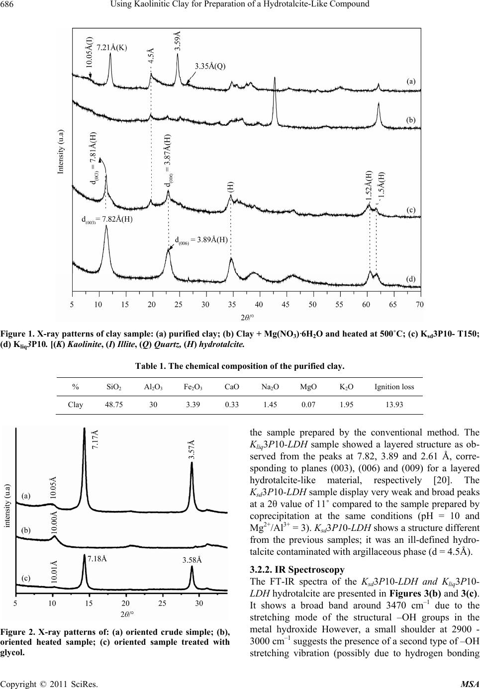 Using Kaolinitic Clay for Preparation of a Hydrotalcite-Like Compound Copyright © 2011 SciRes. MSA 686 Figure 1. X-ray patterns of clay sample: (a) purified clay; (b) Clay + Mg(NO3)·6H2O and heated at 500˚C; (c) Ksd3P10- T150; (d) Kliq3P10. [(K) Kaolinite, (I) Illite, (Q) Quartz, (H) hydrotalcite. Table 1. The chemical composition of the purified clay. % SiO2 Al2O3 Fe2O3 CaO Na2O MgO K2O Ignition loss Clay 48.75 30 3.39 0.33 1.45 0.07 1.95 13.93 the sample prepared by the conventional method. The Kliq3P10-LDH sample showed a layered structure as ob- served from the peaks at 7.82, 3.89 and 2.61 Å, corre- sponding to planes (003), (006) and (009) for a layered hydrotalcite-like material, respectively [20]. The Ksd3P10-LDH sample display very weak and broad peaks at a 2θ value of 11˚ compared to the sample prepared by coprecipitation at the same conditions (pH = 10 and Mg2+/Al3+ = 3). Ksd3P10-LDH shows a structure different from the previous samples; it was an ill-defined hydro- talcite contaminated with argillaceous phase (d = 4.5Å). 3.2.2. IR Spectroscopy The FT-IR spectra of the Ksd3P10-LDH and Kliq3P10- LDH hydrotalcite are presented in Figures 3(b) and 3(c). It shows a broad band around 3470 cm–1 due to the stretching mode of the structural –OH groups in the metal hydroxide However, a small shoulder at 2900 - 3000 cm–1 suggests the presence of a second type of –OH stretching vibration (possibl due to hydrogen bonding Figure 2. X-ray patterns of: (a) oriented crude simple; (b), oriented heated sample; (c) oriented sample treated with glycol. y 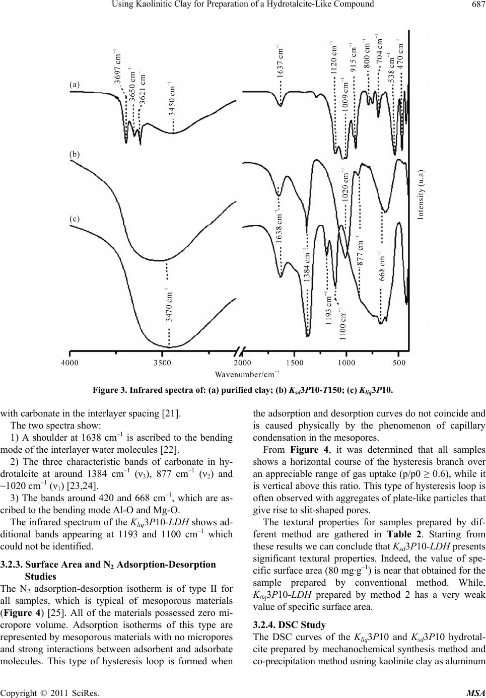 Using Kaolinitic Clay for Preparation of a Hydrotalcite-Like Compound 687 Figure 3. Infrared spectra of: (a) purified clay; (b) Ksd3P10-T150; (c) Kliq3P10. with carbonate in the interlayer spacing [21]. The two spectra show: 1) A shoulder at 1638 cm–1 is ascribed to the bending mode of the interlayer water molecules [22]. 2) The three characteristic bands of carbonate in hy- drotalcite at around 1384 cm–1 (ν3), 877 cm–1 (ν2) and ~1020 cm–1 (ν1) [23,24]. 3) The bands around 420 and 668 cm–1, which are as- cribed to the bending mode Al-O and Mg-O. The infrared spectrum of the Kliq3P10-LDH shows ad- ditional bands appearing at 1193 and 1100 cm–1 which could not be identified. 3.2.3. Surface Area and N2 Adsorption-Desorption Studies The N2 adsorption-desorption isotherm is of type II for all samples, which is typical of mesoporous materials (Figure 4) [25]. All of the materials possessed zero mi- cropore volume. Adsorption isotherms of this type are represented by mesoporous materials with no micropores and strong interactions between adsorbent and adsorbate molecules. This type of hysteresis loop is formed when the adsorption and desorption curves do not coincide and is caused physically by the phenomenon of capillary condensation in the mesopores. From Figure 4, it was determined that all samples shows a horizontal course of the hysteresis branch over an appreciable range of gas uptake (p/p0 ≥ 0.6), while it is vertical above this ratio. This type of hysteresis loop is often observed with aggregates of plate-like particles that give rise to slit-shaped pores. The textural properties for samples prepared by dif- ferent method are gathered in Table 2. Starting from these results we can conclude that Ksd3P10-LDH presents significant textural properties. Indeed, the value of spe- cific surface area (80 mg·g–1) is near that obtained for the sample prepared by conventional method. While, Kliq3P10-LDH prepared by method 2 has a very weak value of specific surface area. 3.2.4. DSC St udy The DSC curves of the Kliq3P10 and Ksd3P10 hydrotal- cite prepared by mechanochemical synthesis method and co-precipitation method usning kaolinite clay as aluminum Copyright © 2011 SciRes. MSA  Using Kaolinitic Clay for Preparation of a Hydrotalcite-Like Compound 688 Figure 4. N2 adsorption-desorption isotherms: (a) Ksd3P10- LDH; (b) Kliq3P10-LDH. Table 2. Textural properties for various sorbent samples. KsdP10 KLiqP10 SBET (m2/g) Vmacropore (cm3/g) SBET (m2/g) Vmacropore (cm3/g) Before calcination 80 0.2044 78 0.6052 After calcination 178 -------- 165 ------ source are shown in Figure 5. Both the DSC profiles exhibited two apparent endothermic events during the thermal decomposition. The first event is at 200˚C for Ksd3P10 and at 198˚C for Kliq3P10, the second thermal event is at 410˚C for Ksd3P10 and at 361˚C for Kliq3P10. In the first decomposition stage, the crystal water re- leased. And in the second decomposition stage, the hy- droxyl (OH–) octahedral structure is destroyed; the hy- droxyl (OH–) and gas of H2O and CO anion release, and CO2, MgO and Al2O3 are formed. The second ther- mal event for Ksd3P10 (410˚C) which more larger than for Kliq3P10 (361˚C) indicated that the sample prepared by kaolinite clay in natural solid state possessed high thermal stability, this observation can be explained by the presence of SO2 in the sample. 2 3 3.2.5. Memory Effect of Calcined Kliq3P10 and Ksd3P10 Hydrotalcite The most important characteristic of layered double hy- droxides is their ability to reconstruct themselves to their original structure. It has already been reported that Mg-Al hydrotalcites can be reconstructed when the sam- ples are calcined below the temperature at which spinel formation does not take place. Figures 6 and 7 show the XRD pattern of samples calcined at 500˚C. From the pattern it was observed that the layered structure was Figure 5. DSC curves of: (a) Ksd3P10-LDH; (b) Kliq3P10- LDH. Figure 6. Powder XRD patterns of Ksd3P10-LDH (a) cal- cined in air at 500˚C; (b) calcined at 500˚C and treated in water for 2 days for reconstruction. completely destroyed, which is clearly indicated by the disappearance of the (003) and (006) peaks at lower 2θ values in the original material (Figures 1(c) and 1(d)). For Ksd3P10-LDH, the Figure 6(a) shows the pres- ence of a peak at 4.5Å due argillaceous phase, which is present as an impure phase, along with peaks due to MgO. To find out whether the hydrotalcite synthesized from the natural clay could be reconstructed to its origi- nal structure, the Ksd3P10-LDH and Kliq3P10-LDH sam- ples, which were previously calcined at 500˚C, was put in water for 2 days. As shown in Figure 6(b) and Figure 7(b), the materials were completely reconstructed to its Copyright © 2011 SciRes. MSA  Using Kaolinitic Clay for Preparation of a Hydrotalcite-Like Compound689 Figure 7. Powder XRD patterns of Kliq3P10-LDH (a) cal- cined in air at 500˚C; (b) calcined at 500˚C and treated in water for 2 days for reconstruction. original layered structure, as indicated by the appearance of the (003) and (006) peaks. 3.3. The Optimisation of the Operating Conditions of Synthesis 3.3.1. The Effect of Mg2+/Al3+ Molar Ra tio The XRD patterns of samples prepared by method 1 at different Mg2+/Al3+ molar ratio show that no hydrotalcite structure was formed when R < 3. From Figure 8, well-crystalline LDH was obtained for Mg2+/Al3+ = 3.0. From Figure 9, it was determined that as the Mg2+/ Al3+ molar ratio increases, from 0.5 to 4, the intensity of 003 and 006 reflections increases, are corresponding to an increase of the formation of the LDH structure. Well-crystalline LDH was obtained for Mg2+/Al3+ =1.0 (Figure 9) belong R = 1, the intensity of 003 and 006 reflections decreases corresponding to the decreasing in cristallinity. 3.3.2. The Effect of of pH of Synthesis The pH of preparation is important in the formation of all hydrotalcite-type materials and the optimum pH depends on the cations used. From Figure 10, it was determined that samples prepared by method 1 and at pH = 8 dis- played very weak, broad reflections at 2θ value of 11˚ compared to Ksd3P10-LDH and Ksd3P12-LDH prepared at pH = 10 and 12 respectively (Figure 10). The XRD patterns of Ksd3P8 (pH = 8) show that no hydrotalcite structure was formed under these synthesis conditions. The broadness of the reflections indicates that the sample was poorly crystalline; brucite was formed instead of hy- drotalcite. Samples prepared within the pH range of 10 - 12 show patterns similar to that of hydrotalcite. The dif- ference between these samples is in the intensity of the Figure.8. X-ray patterns of clay sample synthesized by method 1 at different Mg2+/Al3+ molar ratio. Figure 9. X-ray patterns of clay sample synthesized by method 2 at different R (R = Mg2+/Al3+ molar ratio). Figure 10. X-ray patterns of clay sample synthesized by method 1 at different pH. Copyright © 2011 SciRes. MSA  Using Kaolinitic Clay for Preparation of a Hydrotalcite-Like Compound 690 Figure 11. X-ray patterns of clay sample synthesized by method 2 at different pH. (00l) reflections. Ksd3P10 have the most intense and sharpest reflections, and thus are the most crystalline samples. Samples prepared by method 2 and at pH = 9 dis- played very weak, broad reflections at 2θ value of 11˚ The broadness of the reflections indicates that the sample was poorly crystalline. Samples prepared within the pH range of 10 - 12 show patterns similar to that of hydro- talcite. The difference between these samples is in the intensity of the (00l) reflections. The Kliq3P10 has the most intense and sharpest reflections. Kliq3P12 (pH = 12) shows a structure different from the previous samples; it was contaminated with Al(OH)2. 4. Conclusions Pure and well-crystalline phases of Mg-Al-CO3 LDH can be prepared by coprecipitation and by mechano-chemical synthesis method from the cationic clay (the kaolinite) using an aqueous solution of Na2CO3 as a precipitant. The pH of preparation was an important factor. At pH = 10 well-crystalline LDH was formed. Below this value, the crystallinity of the LDH decreased. Strong alkaline conditions seem no favourable for the synthesis. The optimum values of Mg2+/Al3+ molar ratio depend of the method of synthesize. It was about 3 for synthesize by the method 1 and about 1 for the method 2. Below these ratios poorly crystalline products were obtained. REFERENCES [1] H. F. W. Taylor, “Crystal Structures of Some Double Hydroxide Minerals,” Mineralogical Magazine, Vol. 39, 1973, pp. 377- 389. doi:10.1180/minmag.1973.039.304.01 [2] S. Miyata, “The Syntheses of Hydrotalcite-Like Com- pounds and Their Structures and Physico-Chemical Prop- erties I: The Systems Mg2+-Al3+-3 NO , Mg2+-Al3+-Cl−, Mg2+-Al3+-4 ClO , Ni2+-Al3+-Cl− and Zn2+-Al3+-Cl−,”. Clays Clay Miner, Vol. 23, 1975, pp. 369-375. doi:10.1346/CCMN.1975.0230508 [3] M. Bellotto, B. Rebours, O. Clause, J. Lynch, D. Bazin and E. Elkaim, “Hydrotalcite Decomposition Mechanism: A Clue to the Structure and Reactivity of Spinel-Like Mixed Oxides,” The Journal of Physical Chemistry, Vol. 100, No. 20, 1996, pp. 8535-8542. doi:10.1021/jp960040i [4] F. Cavani, F. Trifiro and A. Vaccari, “Hydrotalcite-Type Anionic Clays: Preparation, Properties and Applications,” Catalysis Today, Vol. 11, No. 2, 1991, pp. 173-301. doi:10.1016/0920-5861(91)80068-K [5] A. De Roy and J. P. Besse, “Conductivité Ionique de Composés de Type Hydrotalcite,” Solid State Ionics, Vol. 35, No. 1-2, 1989, pp. 35-43. doi:10.1016/0167-2738(89)90009-X [6] J. E. Moneyron, A. De Roy and J. P. Besse, “Realization of a Humidity Sensor,” Sensors and Actuators B: Chemi- cal, Vol. 4, No. 1-2, 1991, pp. 189-194. doi:10.1016/0925-4005(91)80197-R [7] G. Carja and G. Delahay, “Mesoporous Mixed Oxides Derived from Pillared Oxovanadates Layered Double hy- Droxides as New Catalysts for the Selective Catalytic Reduction of NO by NH3,” Applied Catalysis B: Envi- ronmental, Vol. 47, No. 1, 2004, pp. 59-66. doi:10.1016/j.apcatb.2003.07.004 [8] H. Schaper, J. J. Berg-Slot and W. H. J. Stork, “Stabilized Magnesia: A Novel Catalyst (Support) Material,” Applied Catalysis, Vol. 54, No. 1, 1989, pp. 79-90. doi:10.1016/S0166-9834(00)82356-8 [9] P. C. Pavan, G. D. Gomes and J. B. Valim, “Adsorption of Sodium Dodecyl Sulfate on Layered Double Hydrox- ides,” Microporous and Mesoporous Materials, Vol. 21, No. 4-6, 1998, pp. 659-665. doi:10.1016/S1387-1811(98)00054-7 [10] P. C. Pavan, E. L. Crepaldi, G. D. Gomes and J. B. Valim, “Adsorption of Sodium Dodecylsulfate on a Hydro- tal-Cite-Like Compound. Effect of Temperature, pH and Ionic Strength,” Colloids and Surfaces A, Vol. 154, No. 3, 1999, pp. 399-410. doi:10.1016/S0927-7757(98)00847-4 [11] M. Meyn, K. Beneke and G. Lagaly, “Anion-Exchange Reactions of Layered Double Hydroxides,” Inorganic Chemistry, Vol. 29, No. 26, 1990, pp. 5201-5207. doi:10.1021/ic00351a013 [12] J. H. Choy, S. Y. Kwak, J. S. Park, Y. J. Jeong and J. Portier, “Intercalative Nanohybrids of Nucleoside Mono- phos-Phates and DNA in Layered Metal Hydroxide,” Journal of the American Chemical Society, Vol. 121, No. 6, 1999, pp. 1399-1400. doi:10.1021/ja981823f [13] J. H. Choy, J. S. Jung, J. M. Oh, M. Park, J. Jeong, Y. K. Kang and O. J. Han, “Layered Double Hydroxide as an Efficient Drug Reservoir for Folate Derivatives,” Bio- materals, Vol. 25, No. 15, 2004, pp. 3059-3064. doi:10.1016/j.biomaterials.2003.09.083 [14] M. Valcheva-Traykova, V. Davidova and A. Weiss, “Thermal Decomposition of Mg, Al-Hydrotalcite Mate- Copyright © 2011 SciRes. MSA  Using Kaolinitic Clay for Preparation of a Hydrotalcite-Like Compound Copyright © 2011 SciRes. MSA 691 rial,” Journal of Materials Science, Vol. 28, 1983, pp. 2157-2162. doi:10.1007/BF00367577 [15] M. Del Acro, P. Del Malet, R. Trujillano and R. Rives,. “Synthesis and Characterization of Hydrotalcites Con- taining Ni(II) and Fe(III) and Their Calcination Prod- ucts,” Journal of Chemistry of. Materials, Vol. 11, No. 3, 1999, pp. 624-633. doi:10.1021/cm9804923 [16] X. Hou and J. R. Kirkpatrick, “Thermal Evolution of the Cl-LiAl2 Layered Double Hydroxide: A Multinuclear MAS NMR and XRD Perspective,” Inorganic Chemistry, Vol. 40, No. 25, 2001, pp. 6397-6404. doi:10.1021/ic010671d [17] P. Beaudot, M. E. De Roy and J.-P. Besse, “Intercalation of Platinum Complex in LDH Compounds,” Journal of Solid State Chemistry, Vol. 161, No. 2, 2001, pp. 332-340. doi:10.1006/jssc.2001.9322 [18] Y. Seida and Y. Nakano, “Removal of Phosphate by Lay- ered Double Hydroxide Containing Iron,” Water Re- search, Vol. 36, No. 5, 2002, pp. 1306-1312. doi:10.1016/S0043-1354(01)00340-2 [19] G. Brindley and G. Brown, “Crystal Structures of Clay Minerals and their X-Ray Identification,” Mineralogical Society, London, 1984 [20] A. De Roy, C. Forano, K. El Malki and J.-P. Besse, “Anionic Clays: Trends in Pillaring Chemistry,” In: M. L. Occelli and H. E. Robson, Eds., Synthesis of Microporous Materials, Van Nostrand Reinhold, New York, 1992, pp. 108-169. [21] J. Das, D. Das and K.M., Parida, “Preparation and Char- acterization of Mg-Al Hydrotalcite-Like Compounds Containing Cerium,” Journal of Colloid and Interface Science, Vol. 301, No. 2, 2006, pp. 569-574. doi:10.1016/j.jcis.2006.05.014 [22] G. Allegra and G. Ronca, “Crystal Powder Statistics. II. Line Profiles in Diffraction Spectra of Identical Crystals and of Gaussian Samples. Crystal Size Distributions,” Acta Crystallographica Section A, Vol. 34, part 6, 1978, pp. 1006-1013. [23] E. Alvarez-Ayuso and H. W. “Nugteren. Purification of Chromium (VI) Finishing Wastewaters Using Calcined and Uncalcined Mg-Al-CO3-Hydrotalcite,” Journal of Water Research, Vol. 39, No. 12, 2005, pp. 2535-2542. doi:10.1016/j.watres.2005.04.069 [24] J. T. Kloprogge, D. Wharton, L. Hickey and R. L. Frost, “Infrared and Raman Study of Interlayer Anions 2 3 CO , 3 NO , 2 4 SO and 4 ClO in Mg/Al-Hydrotalcite,” Jour- nal of American Mineralogist, Vol. 87, 2002, pp. 623- 629. [25] S. J. Gregg and K. S. W. Sing, “Adsorption, Surface Area and Porosity,” 2nd Edition, Academic Press, London, 1982. |