

Paper Menu >>
Journal Menu >>
 Materials Sciences and Applicatio ns, 2011, 2, 596-604 doi:10.4236/msa.2011.26080 Published Online June 2011 (http://www.SciRP.org/journal/msa) Copyright © 2011 SciRes. MSA Predicting the Fatigue Life in Steel and Glass Fiber Reinforced Plastics Using Damage Models Roselita Fragoudakis, Anil Saigal Department of Mechanical Engineering, Tufts University, Medford, USA. Email: [email protected] Received December 20th, 2010; revised March 21st, 2011; accepted March 30th, 2011. ABSTRACT Three cumulative damage models are examined for the case of cyclic loading of AISI 6150 steel, S2 glass fibre/epoxy and E glass fibre/epoxy composites. The Palmgren-Miner, Broutman-Sahu and Hashin-Rotem models are compared to determine which of the three gives the most accurate estimation of the fatigue life of the materials tested. In addition, comparison of the fatigue life of the materials shows the superiority of AISI 6150 steel and S2 glass fibre/epoxy at lower mean stresses, and that of steel to the composites at higher mean stresses. Keywords: Glass Fiber Reinforced Plastic (GFRP), Cumulative Damage Distribution, Low Cycle Fatigue (LCF), High Cycle Fatigue (HCF) 1. Introduction Technological advances require light and durable struc- tures, as is the case in the automotive industry. For this reason composites have replaced metals in many applica- tions. In the case of heavy-duty vehicle suspensions, the market has expanded to composite leaf springs as a re- placement of the conventional steel beams. Composites weigh less than metals and have high strength and stiff- ness [1]. When selecting a material for cyclic loading applications, knowledge of its fatigue life is crucial. It is impossible to predict the fatigue failure of individual specimens, and therefore a statistical approach in deter- mining the fatigue life of materials is necessary. The Weibull distribution helps predict the fatigue life and failure of materials using failure data from specimens subjected to certain loading conditions and is essential when the materials involved are brittle as in the case of composites [1,2]. The ensemble of attempts to calculate the damage caused by cycling, as well as its accumulation when cy- cling includes more than one stress amplitudes, is Cu- mulative Damage Theory [3]. The concept of cumulative damage can be discussed either based on residual strength, being the instantaneous static strength that the material can still maintain after being loaded to stress levels causing damage, or the estimation of cumulative damage through damage models, such as the ones dis- cussed in this study [4]. Contrary to the case of homogeneous isotropic materi- als such as metals where fatigue failure is characterized by the initiation and propagation of a crack, fatigue fail- ure in composites is the result of accumulated damage [1,5]. In metals the strength of the material may change little, if at all, during cycling fatigue, while crack propa- gation is what will define the fatigue damage [6]. Com- posites behave very differently, as their strength starts decreasing slowly early in their fatigue life, and as failure approaches, the rate of decreasing strengths becomes very rapid [7]. The damage generated in a material under loading can be predicted using damage models even when minimum information on the fatigue of the mate- rial is known. The intensity of the stress being applied has a different effect in composites and metals. In a metal structure the stresses that are critical in designing a metal structure are low stresses, while in composites it is higher stresses that define low cycle fatigue, that become critical when de- signing a composite structure [8]. 2. Damage Models and Materials This study uses the following three damage models to predict and compare the damage caused in AISI 6150 steel and unidirectional Glass Fiber Reinforced Plastics (GFRP), S2 glass fibre/epoxy and E glass fibre/epoxy, under cyclic loading conditions: Palmgren-Miner [9-11]:  Predicting the Fatigue Life in Steel and Glass Fiber Reinforced Plastics Using Damage Models597 1 1 n i ii nK N (1) Broutman-Sahu [10,12]: 11 1 nUltimate ii iUltimate ii nK N (2) and Hashin-Rotem [3,10]: 1 1 1 1 11 1 k k S S nki ii k nnK NN (3) k k Ultimate S (3a) 1 1 k k Ultimate S (3b) where ni is the number of cycles under the applied stress, Ni the cycles to failure under this same stress, σi and σk are the stresses applied, Ultimate is the ultimate strength, Sk is the ratio of the applied stress to the ultimate strength, and K is the number of repetitions of the loading cycle. When each of these equations equals 1, the damage ac- cumulated leads to failure. However, damage is still be- ing caused even if the right hand side of the above equa- tions is less than 1 [3,4,9-13]. A specimen may be subjected to one or more stress levels and undergo cycling. When there are two stress levels, where 1 and 2 are imposed on the specimen for an amount of n1 and n2 cycles, respectively, n2 is the number of cycles that will lead the specimen to failure, called the residual lifetime. Residual lifetime can be pre- dicted by all three of the above models, when their ma- thematical expression equals 1, i.e. at failure. The cou- ples i and ni are the stress and respective number of cy- cles used to create a damage curve. The damage curve shows the ultimate damage caused to the specimen, when its residual life is zero. Such a curve is called S-N curve. Each point on a damage curve, defined by ( , n), repre- sents the damage caused to a specimen after n cycles under a load . As a result it can be concluded, that damage is a way to describe the life of the specimen that is spent when it is loaded at . The ratio ni/Ni represents a life fraction for the specimen being loaded at i [3]. The Palmgren-Miner model defines damage in the mate- rial, in the form of life fractions, the sum of which when 1 defines failure of the material when no more residual life remains to be expended. The other two models also define damage in the form of life fractions, but in these two cases the models account for the loading sequence, which is not accounted for in Palmgren-Miner. The Palmgren-Miner damage rule, also referred to as Miner’s sum, expresses damage in terms of cycles ap- plied at a stress level, divided by the number of cycles that lead to failure at this stress level. Each such ratio represents a percentage of life consumed [3,8,12]. When the summation of all these ratios equals 1, as given by (1), the specimen has failed. In the Palmgren-Miner damage rule the order in which the stresses are applied to the specimen has no effect in its fatigue life [11]. When a metal component is undergoing a two-stress level loading, damage, according to Palmgren-Miner rule, is greater when the first stress is higher than the second stress (in such case the sum in (1) is close or higher than 1), and less damage occurs when the loading sequence is a low to high stress (when the sum in (1) is less than 1) [11,12]. Broutman and Sahu presented a modified Min- er’s sum, in order to account for this discrepancy of Miner’s sum from unity. Broutman and Sahu used the linear strength reduction curves, and assuming that the residual strength is a linear function of the fractional life spent when the component is loaded at a given stress level, predicted more accurately the fatigue behavior in GFRP, especially at higher stress levels [12]. Hashin and Rotem used the concept of damage curve families to represent residual lifetimes for two-stress lev- el loading, as well as the fact that equivalent residual lives are expended by specimens that undergo different loading schemes1. They developed a cumulative damage model to predict damage in two-stress level loading, which can be expanded for use in multi-stress level loadings [3]. As mentioned above, the Palmgren-Miner rule has been shown not to account for loading sequences, as the sum can be calculated irrespective of the loading order. As a result for a high-low stress test the predicted cumu- lative damage by this model is greater than 1, and for a sequence of low-high stress the sum is less than 1 [3, 11,12]. The other two models, which take into account the order of loading, give more accurate results. Palm- gren-Miner and Hashin-Rotem rules have been initially designed and tested on metals, although later used in GFRP damage predictions. Broutman-Sahu rule was de- veloped and tested on GFRP. A classification of the damage models can be made based on their linearity or non-linearity, and according to the parameters required for their calculation [1]. Conse- quently, Palmgren-Miner is a linear stress independent model, Broutman-Sahu is a linear stress dependent model and Hashin-Rotem is a non-linear stress dependent mod- 1This is referred to as the equivalent loading postulate that states: “cy- clic loadings which are equivalent for one stress level are equivalen t f or all stress levels” [3]. Copyright © 2011 SciRes. MSA 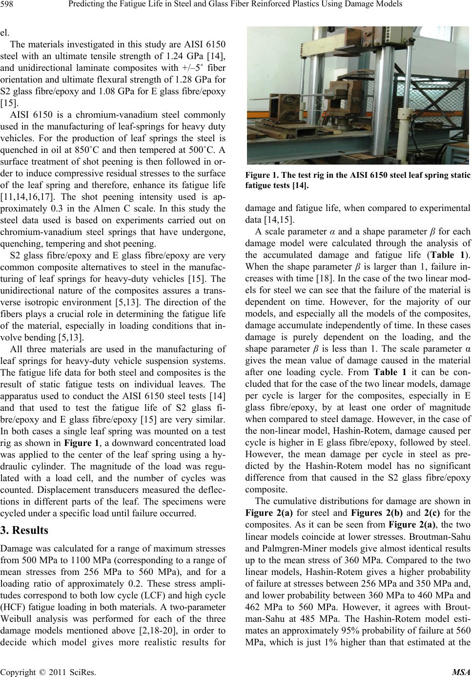 Predicting the Fatigue Life in Steel and Glass Fiber Reinforced Plastics Using Damage Models 598 el. The materials investigated in this study are AISI 6150 steel with an ultimate tensile strength of 1.24 GPa [14], and unidirectional laminate composites with +/–5˚ fiber orientation and ultimate flexural strength of 1.28 GPa for S2 glass fibre/epoxy and 1.08 GPa for E glass fibre/epoxy [15]. AISI 6150 is a chromium-vanadium steel commonly used in the manufacturing of leaf-springs for heavy duty vehicles. For the production of leaf springs the steel is quenched in oil at 850˚C and then tempered at 500˚C. A surface treatment of shot peening is then followed in or- der to induce compressive residual stresses to the surface of the leaf spring and therefore, enhance its fatigue life [11,14,16,17]. The shot peening intensity used is ap- proximately 0.3 in the Almen C scale. In this study the steel data used is based on experiments carried out on chromium-vanadium steel springs that have undergone, quenching, tempering and shot peening. S2 glass fibre/epoxy and E glass fibre/epoxy are very common composite alternatives to steel in the manufac- turing of leaf springs for heavy-duty vehicles [15]. The unidirectional nature of the composites assures a trans- verse isotropic environment [5,13]. The direction of the fibers plays a crucial role in determining the fatigue life of the material, especially in loading conditions that in- volve bending [5,13]. All three materials are used in the manufacturing of leaf springs for heavy-duty vehicle suspension systems. The fatigue life data for both steel and composites is the result of static fatigue tests on individual leaves. The apparatus used to conduct the AISI 6150 steel tests [14] and that used to test the fatigue life of S2 glass fi- bre/epoxy and E glass fibre/epoxy [15] are very similar. In both cases a single leaf spring was mounted on a test rig as shown in Figure 1, a downward concentrated load was applied to the center of the leaf spring using a hy- draulic cylinder. The magnitude of the load was regu- lated with a load cell, and the number of cycles was counted. Displacement transducers measured the deflec- tions in different parts of the leaf. The specimens were cycled under a specific load until failure occurred. 3. Results Damage was calculated for a range of maximum stresses from 500 MPa to 1100 MPa (corresponding to a range of mean stresses from 256 MPa to 560 MPa), and for a loading ratio of approximately 0.2. These stress ampli- tudes correspond to both low cycle (LCF) and high cycle (HCF) fatigue loading in both materials. A two-parameter Weibull analysis was performed for each of the three damage models mentioned above [2,18-20], in order to decide which model gives more realistic results for Figure 1. The test rig in the AISI 6150 steel leaf spring static fatigue tests [14]. damage and fatigue life, when compared to experimental data [14,15]. A scale parameter α and a shape parameter β for each damage model were calculated through the analysis of the accumulated damage and fatigue life (Table 1). When the shape parameter β is larger than 1, failure in- creases with time [18]. In the case of the two linear mod- els for steel we can see that the failure of the material is dependent on time. However, for the majority of our models, and especially all the models of the composites, damage accumulate independently of time. In these cases damage is purely dependent on the loading, and the shape parameter β is less than 1. The scale parameter α gives the mean value of damage caused in the material after one loading cycle. From Table 1 it can be con- cluded that for the case of the two linear models, damage per cycle is larger for the composites, especially in E glass fibre/epoxy, by at least one order of magnitude when compared to steel damage. However, in the case of the non-linear model, Hashin-Rotem, damage caused per cycle is higher in E glass fibre/epoxy, followed by steel. However, the mean damage per cycle in steel as pre- dicted by the Hashin-Rotem model has no significant difference from that caused in the S2 glass fibre/epoxy composite. The cumulative distributions for damage are shown in Figure 2(a) for steel and Figures 2(b) and 2(c) for the composites. As it can be seen from Figure 2(a), the two linear models coincide at lower stresses. Broutman-Sahu and Palmgren-Miner models give almost identical results up to the mean stress of 360 MPa. Compared to the two linear models, Hashin-Rotem gives a higher probability of failure at stresses between 256 MPa and 350 MPa and, and lower probability between 360 MPa to 460 MPa and 462 MPa to 560 MPa. However, it agrees with Brout- man-Sahu at 485 MPa. The Hashin-Rotem model esti- mates an approximately 95% probability of failure at 560 MPa, which is just 1% higher than that estimated at the Copyright © 2011 SciRes. MSA  Predicting the Fatigue Life in Steel and Glass Fiber Reinforced Plastics Using Damage Models599 Table 1. Shape and scale parameters for all damage models. Palmgren-Miner Broutman-Sahu Hashin-Rotem β 6150 steel 1.18 1.89 0.40 β E glass/fibre 0.22 0.28 0.38 β S2 glass/fibre 0.28 0.37 0.42 α 6150 steel 6.21 × 10⁻⁶ 3.51 × 10⁻⁶ 1.17 × 10⁻² α E glass/fibre 1.29 × 10⁻³ 2.68 × 10⁻⁴ 0.41 α S2 glass/fibre 5.06 × 10⁻⁵ 2.08 × 10⁻⁵ 8.49 × 10⁻³ (a) (b) (c) Figure 2. Cumulative distribution of damage versus mean stress: (a) AISI 6150 steel, (b) S2 glass fibre/epoxy compos- ite, (c) E glass fibre/epoxy composite. same mean stress lever by the two linear models. For the S2 glass fibre/epoxy composite (Figure 2(b)) the two linear models give similar results at almost all mean stresses. For the interval between 256 MPa and 350 MPa, Hashin-Rotem gives a lower probability of failure than Broutman-Sahu and Palmgren-Miner. For stresses from 350 MPa to 485 MPa Hashin-Rotem gives higher probability of failure, but at 485 MPa gives a failure probability very close to that of the other two models. For the case of the S2 glass fibre/epoxy composite, Ha- shin-Rotem gives failure probability at 560 MPa, same as that estimated by the model for the case of the steel, which is approximately 95%, 2% lower than the estimate of the two linear models at the same mean stress. In the case of E glass fibre/epoxy composite, the two linear models give almost identical results. Both Palm- gren-Miner and Broutman-Sahu show a constant prob- ability of failure at low mean stresses up to 280 MPa. For both cases of the linear models failure probability at these mean stress levels is approximately 19%. Figure 2(c) shows that the Broutman-Sahu model gives a bit lower probability of failure at mean stresses between 350 MPa and 400 MPa, and higher values at 460 MPa to 485 MPa. However, these values of failure probability when compared to the results of the Palmgren-Miner model differ by at most 1%. At 560 MPa, all three mod- els give a prediction of total failure, where cumulative damage is 1. This is due to the fact that this mean stress level at a stress ratio of 0.2 corresponds to a maximum stress of 1.1 GPa, which is higher than the ultimate ten- sile strength of the material. The Hashin-Rotem model starts with lower probability of failure, than the linear models, but the cumulative damage increases between 280 MPa and 360 MPa, giving a probability 5% higher than the Palmgren-Miner model. Above the mean stress of 360 MPa it agrees with the two linear models, with differences less than 0.1%. For all three materials, and especially in the cases of steel and E glass fibre/epoxy, it is observed from the graphs that the curve based on the Hashin-Rotem model is a smooth curve resembling a best-fit line for the other two curves of the two linear damage models. It is also worth mentioning that the deviation of Hashin-Rotem from the other two models is larger in the case of the S2 glass fiber/epoxy composite and smaller in E glass fi- bre/epoxy. The maximum deviation in steel at 360 MPa is 26% less than the other two models. In the S2 glass fibre/epoxy Hashin-Rotem deviates the most from the two linear models between 462 MPa to 485 MPa. At these mean stress levels the non-linear model gives ap- proximately 31% more damage probability than Palm- gren-Miner and Broutman-Sahu models. Finally, in E glass fibre/epoxy the highest deviation of the Hashin- Copyright © 2011 SciRes. MSA 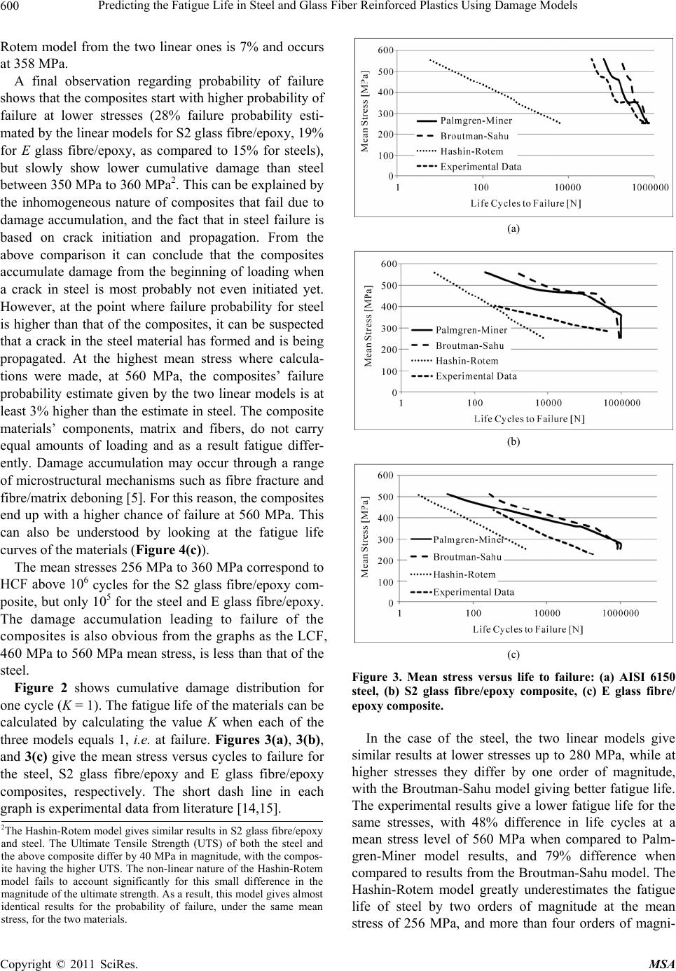 Predicting the Fatigue Life in Steel and Glass Fiber Reinforced Plastics Using Damage Models 600 Rotem model from the two linear ones is 7% and occurs at 358 MPa. A final observation regarding probability of failure shows that the composites start with higher probability of failure at lower stresses (28% failure probability esti- mated by the linear models for S2 glass fibre/epoxy, 19% for E glass fibre/epoxy, as compared to 15% for steels), but slowly show lower cumulative damage than steel between 350 MPa to 360 MPa2. This can be explained by the inhomogeneous nature of composites that fail due to damage accumulation, and the fact that in steel failure is based on crack initiation and propagation. From the above comparison it can conclude that the composites accumulate damage from the beginning of loading when a crack in steel is most probably not even initiated yet. However, at the point where failure probability for steel is higher than that of the composites, it can be suspected that a crack in the steel material has formed and is being propagated. At the highest mean stress where calcula- tions were made, at 560 MPa, the composites’ failure probability estimate given by the two linear models is at least 3% higher than the estimate in steel. The composite materials’ components, matrix and fibers, do not carry equal amounts of loading and as a result fatigue differ- ently. Damage accumulation may occur through a range of microstructural mechanisms such as fibre fracture and fibre/matrix deboning [5]. For this reason, the composites end up with a higher chance of failure at 560 MPa. This can also be understood by looking at the fatigue life curves of the materials (Figure 4(c)). The mean stresses 256 MPa to 360 MPa correspond to HCF above 106 cycles for the S2 glass fibre/epoxy com- posite, but only 105 for the steel and E glass fibre/epoxy. The damage accumulation leading to failure of the composites is also obvious from the graphs as the LCF, 460 MPa to 560 MPa mean stress, is less than that of the steel. Figure 2 shows cumulative damage distribution for one cycle (K = 1). The fatigue life of the materials can be calculated by calculating the value K when each of the three models equals 1, i.e. at failure. Figures 3(a), 3(b), and 3(c) give the mean stress versus cycles to failure for the steel, S2 glass fibre/epoxy and E glass fibre/epoxy composites, respectively. The short dash line in each graph is experimental data from literature [14,15]. (a) (b) (c) Figure 3. Mean stress versus life to failure: (a) AISI 6150 steel, (b) S2 glass fibre/epoxy composite, (c) E glass fibre/ epoxy composite. In the case of the steel, the two linear models give similar results at lower stresses up to 280 MPa, while at higher stresses they differ by one order of magnitude, with the Broutman-Sahu model giving better fatigue life. The experimental results give a lower fatigue life for the same stresses, with 48% difference in life cycles at a mean stress level of 560 MPa when compared to Palm- gren-Miner model results, and 79% difference when compared to results from the Broutman-Sahu model. The Hashin-Rotem model greatly underestimates the fatigue life of steel by two orders of magnitude at the mean stress of 256 MPa, and more than four orders of magni- 2The Hashin-Rotem model gives similar results in S2 glass fi b re/epoxy and steel. The Ultimate Tensile Strength (UTS) of both the steel and the above composite differ by 40 MPa in magnitude, with the compos- ite having the higher UTS. The non-linear nature of the Hashin-Rotem model fails to account significantly for this small difference in the magnitude of the ultimate strength. As a result, this model gives almost identical results for the probability of failure, under the same mean stress, for the two materials. Copyright © 2011 SciRes. MSA 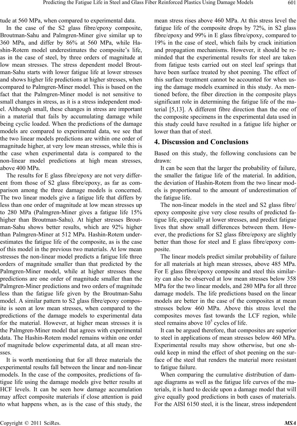 Predicting the Fatigue Life in Steel and Glass Fiber Reinforced Plastics Using Damage Models601 tude at 560 MPa, when compared to experimental data. In the case of the S2 glass fibre/epoxy composite, Broutman-Sahu and Palmgren-Miner give similar up to 360 MPa, and differ by 86% at 560 MPa, while Ha- shin-Rotem model underestimates the composite’s life, as in the case of steel, by three orders of magnitude at low mean stresses. The stress dependent model Brout- man-Sahu starts with lower fatigue life at lower stresses and shows higher life predictions at higher stresses, when compared to Palmgren-Miner model. This is based on the fact that the Palmgren-Miner model is not sensitive to small changes in stress, as it is a stress independent mod- el. Although small, these changes in stress are important in a material that fails by accumulating damage while being cyclic loaded. When the predictions of the damage models are compared to experimental data, we see that the two linear models predictions are within one order of magnitude higher, at very low mean stresses, while this is the case when experimental data is compared to the non-linear model predictions at high mean stresses, above 400 MPa. The results for E glass fibre/epoxy are not very differ- ent from those of S2 glass fibre/epoxy, as far as com- parison among the three damage models is concerned. The two linear models give a fatigue life that differs by less than one order of magnitude at low mean stresses up to 280 MPa (Palmgren-Miner gives a fatigue life 15% higher than Broutman-Sahu). At higher stresses Brout- man-Sahu shows better results, which are 92% higher than Palmgren-Miner at 512 MPa. Hashin-Rotem under- estimates the fatigue life of the composite, as is the case of this model in the previous two materials. At low mean stresses the non-linear model predicts a fatigue life three orders of magnitude smaller than that predicted by the Palmgren-Miner model, while at higher stresses these predictions are one order of magnitude smaller than the Palmgren-Miner predictions and two orders of magnitude less than the fatigue life given by the Broutman-Sahu model. A similar pattern to S2 glass fibre/epoxy compos- ite is seen at low mean stresses, when compared to the predictions of the damage models to experimental data for the material. However, at higher mean stresses it is the Palmgren-Miner model that agrees with experimental data. The Hashin-Rotem model remains within one order of magnitude below experimental data, at all mean stre- sses. It is worth mentioning that for all three materials the experimental results fall between the linear and non-linear models. In the case of the composites, predictions of fa- tigue life using the damage models give better results at HCF levels. It can be seen how damage accumulation may affect composite materials if close attention is paid to what happens when, as is the case of this study, the mean stress rises above 460 MPa. At this stress level the fatigue life of the composite drops by 72%, in S2 glass fibre/epoxy and 99% in E glass fibre/epoxy, compared to 19% in the case of steel, which fails by crack initiation and propagation mechanisms. However, it should be re- minded that the experimental results for steel are taken from fatigue tests carried out on steel leaf springs that have been surface treated by shot peening. The effect of this surface treatment cannot be accounted for when us- ing the damage models examined in this study. As men- tioned before, the fiber direction in the composite plays significant role in determining the fatigue life of the ma- terial [5,13]. A different fibre direction than the one of the composite specimens in the experimental data used in this study could have resulted in a fatigue life higher or lower than that of steel. 4. Discussion and Conclusions Based on this study, the following conclusions can be drawn: It can be seen that the larger the probability of failure, the smaller the fatigue life of the material. In addition, the deviation of Hashin-Rotem from the two linear mod- els is proportional to the amount of underestimation of the fatigue life. The non-linear models in the steel and S2 glass fibre/ epoxy composite give very close results of predicted fa- tigue life, especially at lower stresses, and predict fatigue lives that show small differences between them. How- ever, the predictions for S2 glass fibre/epoxy are slightly better than those for steel and E glass fibre/epoxy com- posite. The linear models predict similar probability of failure for all materials at high mean stresses, above 485 MPa. For E glass fibre/epoxy composite and steel this similar- ity can also be observed at low mean stresses below 358 MPa for the two linear models, and 280 MPa for all three damage models. The life predictions based on the linear models are better in the case of the composites at mean stresses below 460 MPa. Above this stress level the composites moves fast towards the LCF region, while steel remains above 105 cycles of life. It can be argued therefore, that composites are superior to steel in applications of mean stresses below 460 MPa. Experimental results may show otherwise, but one sh- ould keep in mind the effect of shot peening on the sur- face of the steel that renders the material more resistant to fatigue failure. When comparing the cumulative distribution of dam- age diagrams as well as the fatigue life curves of the ma- terials, it is hard to decide upon a damage model that will give equally good predictions in both cases of materials. For the AISI 6150 steel, it is the linear, stress independent Copyright © 2011 SciRes. MSA 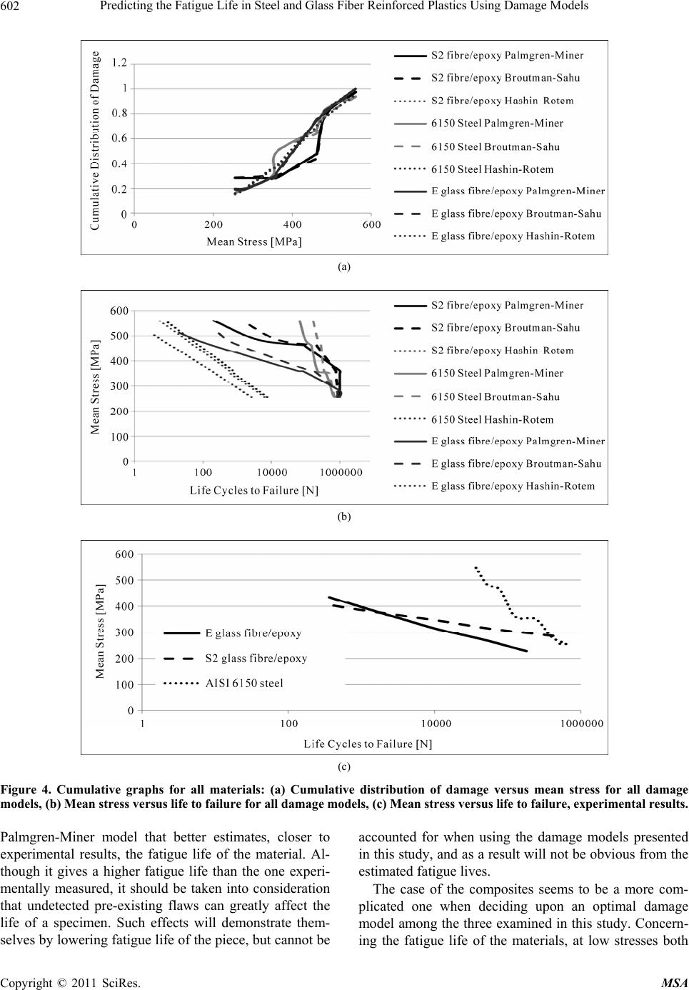 Predicting the Fatigue Life in Steel and Glass Fiber Reinforced Plastics Using Damage Models Copyright © 2011 SciRes. MSA 602 (a) (b) (c) Figure 4. Cumulative graphs for all materials: (a) Cumulative distribution of damage versus mean stress for all damage models, (b) Mean stress versus life to failure for all damage models, (c) Mean stress versus life to failure, experimental results. Palmgren-Miner model that better estimates, closer to experimental results, the fatigue life of the material. Al- though it gives a higher fatigue life than the one experi- mentally measured, it should be taken into consideration that undetected pre-existing flaws can greatly affect the life of a specimen. Such effects will demonstrate them- selves by lowering fatigue life of the piece, but cannot be accounted for when using the damage models presented in this study, and as a result will not be obvious from the estimated fatigue lives. The case of the composites seems to be a more com- plicated one when deciding upon an optimal damage model among the three examined in this study. Concern- ing the fatigue life of the materials, at low stresses both 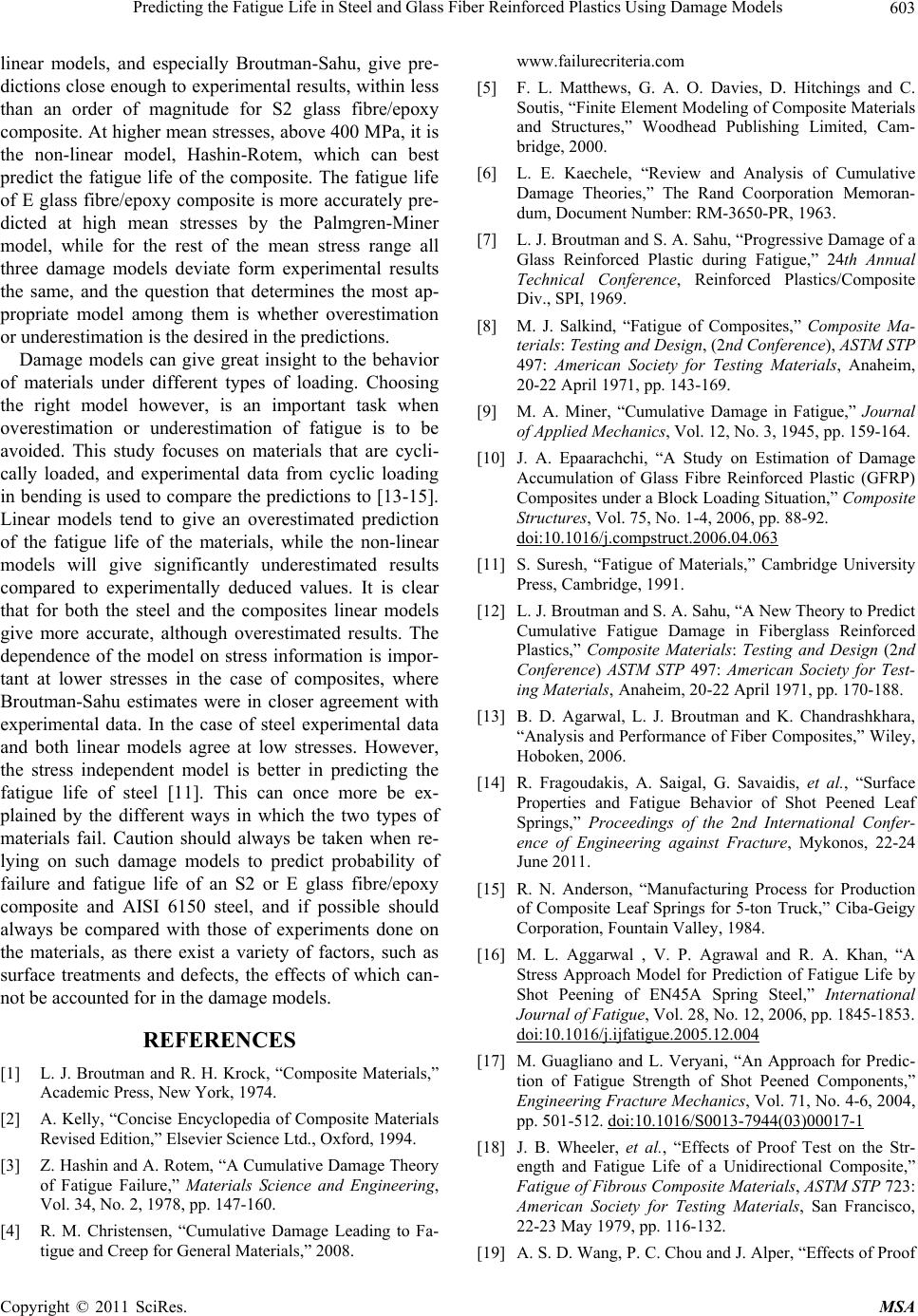 Predicting the Fatigue Life in Steel and Glass Fiber Reinforced Plastics Using Damage Models603 linear models, and especially Broutman-Sahu, give pre- dictions close enough to experimental results, within less than an order of magnitude for S2 glass fibre/epoxy composite. At higher mean stresses, above 400 MPa, it is the non-linear model, Hashin-Rotem, which can best predict the fatigue life of the composite. The fatigue life of E glass fibre/epoxy composite is more accurately pre- dicted at high mean stresses by the Palmgren-Miner model, while for the rest of the mean stress range all three damage models deviate form experimental results the same, and the question that determines the most ap- propriate model among them is whether overestimation or underestimation is the desired in the predictions. Damage models can give great insight to the behavior of materials under different types of loading. Choosing the right model however, is an important task when overestimation or underestimation of fatigue is to be avoided. This study focuses on materials that are cycli- cally loaded, and experimental data from cyclic loading in bending is used to compare the predictions to [13-15]. Linear models tend to give an overestimated prediction of the fatigue life of the materials, while the non-linear models will give significantly underestimated results compared to experimentally deduced values. It is clear that for both the steel and the composites linear models give more accurate, although overestimated results. The dependence of the model on stress information is impor- tant at lower stresses in the case of composites, where Broutman-Sahu estimates were in closer agreement with experimental data. In the case of steel experimental data and both linear models agree at low stresses. However, the stress independent model is better in predicting the fatigue life of steel [11]. This can once more be ex- plained by the different ways in which the two types of materials fail. Caution should always be taken when re- lying on such damage models to predict probability of failure and fatigue life of an S2 or E glass fibre/epoxy composite and AISI 6150 steel, and if possible should always be compared with those of experiments done on the materials, as there exist a variety of factors, such as surface treatments and defects, the effects of which can- not be accounted for in the damage models. REFERENCES [1] L. J. Broutman and R. H. Krock, “Composite Materials,” Academic Press, New York, 1974. [2] A. Kelly, “Concise Encyclopedia of Composite Materials Revised Edition,” Elsevier Science Ltd., Oxford, 1994. [3] Z. Hashin and A. Rotem, “A Cumulative Damage Theory of Fatigue Failure,” Materials Science and Engineering, Vol. 34, No. 2, 1978, pp. 147-160. [4] R. M. Christensen, “Cumulative Damage Leading to Fa- tigue and Creep for General Materials,” 2008. www.failurecriteria.com [5] F. L. Matthews, G. A. O. Davies, D. Hitchings and C. Soutis, “Finite Element Modeling of Composite Materials and Structures,” Woodhead Publishing Limited, Cam- bridge, 2000. [6] L. E. Kaechele, “Review and Analysis of Cumulative Damage Theories,” The Rand Coorporation Memoran - dum, Document Number: RM-3650-PR, 1963. [7] L. J. Broutman and S. A. Sahu, “Progressive Damage of a Glass Reinforced Plastic during Fatigue,” 24th Annual Technical Conference, Reinforced Plastics/Composite Div., SPI, 1969. [8] M. J. Salkind, “Fatigue of Composites,” Composite Ma- terials: Testing and Design, (2nd Conference), ASTM STP 497: American Society for Testing Materials, Anaheim, 20-22 April 1971, pp. 143-169. [9] M. A. Miner, “Cumulative Damage in Fatigue,” Journal of Applied Mechanics, Vol. 12, No. 3, 1945, pp. 159-164. [10] J. A. Epaarachchi, “A Study on Estimation of Damage Accumulation of Glass Fibre Reinforced Plastic (GFRP) Composites under a Block Loading Situation,” Composite Structures, Vol. 75, No. 1-4, 2006, pp. 88-92. doi:10.1016/j.compstruct.2006.04.063 [11] S. Suresh, “Fatigue of Materials,” Cambridge University Press, Cambridge, 1991. [12] L. J. Broutman and S. A. Sahu, “A New Theory to Predict Cumulative Fatigue Damage in Fiberglass Reinforced Plastics,” Composite Materials: Testing and Design (2nd Conference) ASTM STP 497: American Society for Test- ing Materials, Anaheim, 20-22 April 1971, pp. 170-188. [13] B. D. Agarwal, L. J. Broutman and K. Chandrashkhara, “Analysis and Performance of Fiber Composites,” Wiley, Hoboken, 2006. [14] R. Fragoudakis, A. Saigal, G. Savaidis, et al., “Surface Properties and Fatigue Behavior of Shot Peened Leaf Springs,” Proceedings of the 2nd International Confer- ence of Engineering against Fracture, Mykonos, 22-24 June 2011. [15] R. N. Anderson, “Manufacturing Process for Production of Composite Leaf Springs for 5-ton Truck,” Ciba-Geigy Corporation, Fountain Valley, 1984. [16] M. L. Aggarwal , V. P. Agrawal and R. A. Khan, “A Stress Approach Model for Prediction of Fatigue Life by Shot Peening of EN45A Spring Steel,” International Journal of Fatigue, Vol. 28, No. 12, 2006, pp. 1845-1853. doi:10.1016/j.ijfatigue.2005.12.004 [17] M. Guagliano and L. Veryani, “An Approach for Predic- tion of Fatigue Strength of Shot Peened Components,” Engineering Fracture Mechanics, Vol. 71, No. 4-6, 2004, pp. 501-512. doi:10.1016/S0013-7944(03)00017-1 [18] J. B. Wheeler, et al., “Effects of Proof Test on the Str- ength and Fatigue Life of a Unidirectional Composite,” Fatigue of Fibrous Composite Materials, ASTM STP 723: American Society for Testing Materials, San Francisco, 22-23 May 1979, pp. 116-132. [19] A. S. D. Wang, P. C. Chou and J. Alper, “Effects of Proof Copyright © 2011 SciRes. MSA  Predicting the Fatigue Life in Steel and Glass Fiber Reinforced Plastics Using Damage Models Copyright © 2011 SciRes. MSA 604 Test on the Strength and Fatigue Life of a Unidirectional Composite,” Interim Technical Report, Accession Num- ber: ADA076334, 1979. [20] D. N. P. Murthy, M. Xin and R. Jiang, “Weibull Models,” Wiley, Hoboken, 2004. |