

Paper Menu >>
Journal Menu >>
 Natural Resources, 2011, 2, 75-86 doi:10.4236/nr.2011.22010 Published Online June 2011 (http://www.scirp.org/journal/nr) Copyright © 2011 SciRes. NR 75 A Combined Solar Photovoltaic Distributed Energy Source Appliance Himanshu Dehra 1-140 Avenue Windsor, Lachine, Québec , Canada. E-mail: [email protected] Received November 29th, 2010; revised January 18th, 2011; accepted January 25th, 2011. ABSTRACT The paper has analysed the state-of-art technology for a solar photovoltaic distributed energy source appliance. The success of implementation of photovoltaic (PV) power project is increased when PV module system is integrated with building design process and is used as multi purpose appliance for use with building elements. The improvement in overall system efficiency of building integrated PV modules embedded in building façade is achieved by minimizing and capturing energy losses. A novel solar energy utilisation technology for generation of electric and thermal power is presented by integration of ventilation and solar photovoltaic device with the heating, ventilating and air conditioning (HVAC) system. The testing appliance named as photovoltaic duct wall was a wooden frame assembly of double wall with air ventilation: two adjacent glass coated PV modules, air column, plywood board filled with polystyrene and dampers. The measurement data is collected from various sensors to read measurements of solar intensity, ambient air temperature, room air temperature, electric power, surface temperatures of PV modules and plywood board, air veloci- ties and air temperatures in the air column. The enhancement in the air velocity of the air column is fulfilled with an exhaust fan fixed in an outdoor room. The simulation model is used to perform the two dimensional energy analyses with applied one dimensional solution of steady state heat conduction equations. The bases of simulation model are conjugating energy travel paths with network boundary conditions of convection, radiation exchange, heat storage ca- pacity, thermal storage capacity and heat transport. Keywords: HVAC, Energy Source, Energy Appliance, Energy Distribution, Photovoltaic Duct 1. Introduction With increase in cost of fuel and electricity and increase in greenhouse gas productions, there is a rise in activity trend towards use of solar energy utilisation technologies for energy and environment conservation. The traditional techniques of passive solar heating are applied in build- ings since historical times by generation of solar heat and transmission of heat flow inside the building with use of thermo siphon principle to move warm air [1-4]. The active solar systems make use of mechanical and electri- cal equipment such as fans and pumps to circulate the heat of fluid effectively [5-7]. The examples of active solar systems are roof top col- lectors for heating of water and air for inside use in the building. In active space heating systems, either air or liquid or phase changing material is used to collect solar heat and to supply to the occupied space either directly or its heating load is combined with building heating utility system. The examples are solar air heaters, solar chimney, ventilated façades and earth-coupled heat structures. Solar energy is also used to operate cooling equipment by supplying solar heat to any of several types of heat generation cycles. The first usable solar cell was invented at Bell labora- tories in 1954. A photovoltaic (PV) or solar cell is a solid state device that converts sunlight and electromagnetic radiation into electricity. The energy losses in a solar cell are to the tune of 85%, which result from several factors [1]. The intensity of solar radiation is usually lower than standard test value of 1000 Wm−2, as atmospheric ab- sorption of the solar radiation spectrum reduces the available solar radiation below this value [1]. The elec- trical efficiencies are also reduced because incident solar radiation is often not perpendicular to the plane of the photovoltaic modules. Moreover, solar cell temperatures are often higher than the nominal operating cell tem- perature (NOCT) of 25˚C, so that the diode current that opposes the light generating current is higher than in test 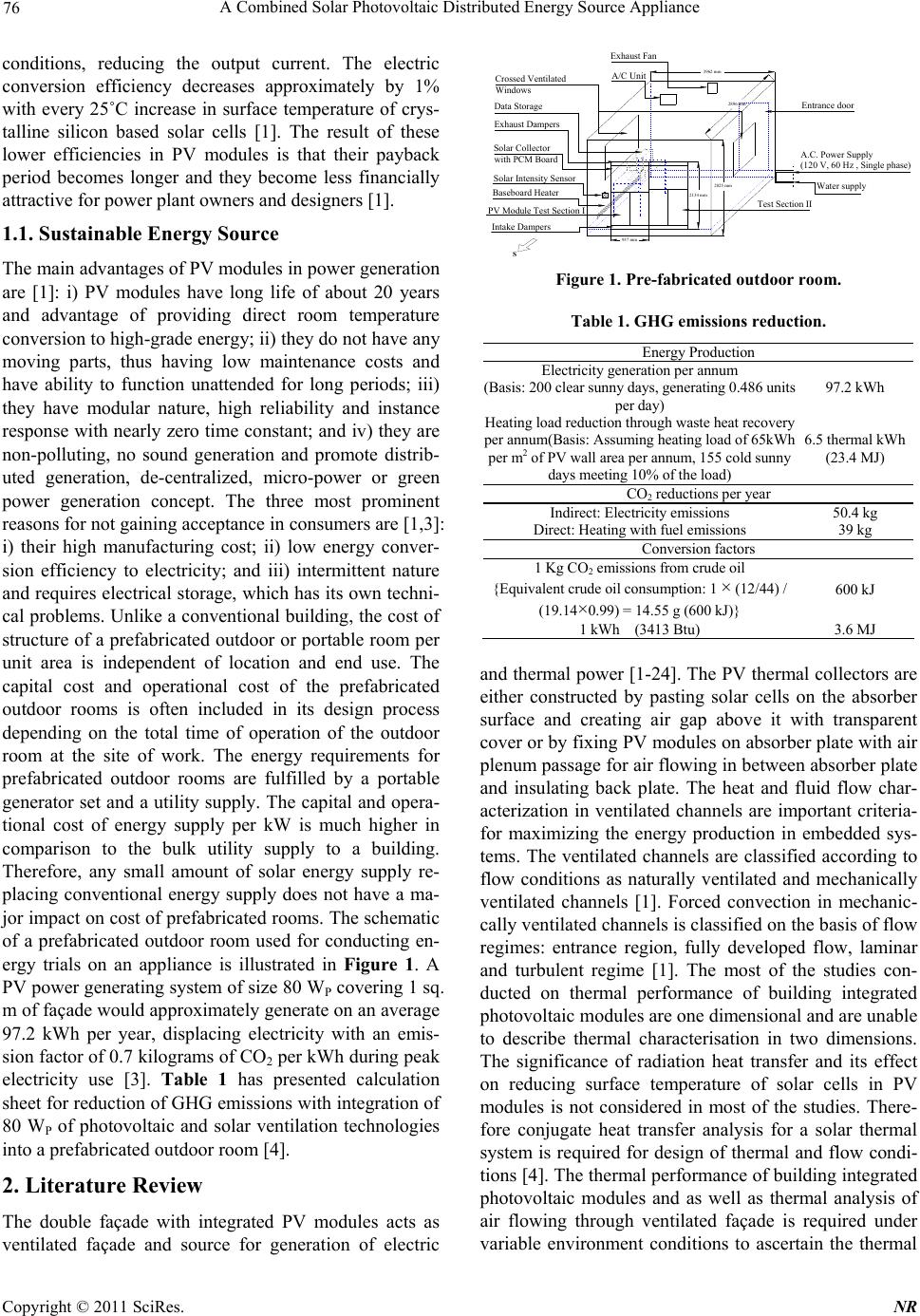 76 A Combined Solar Photovoltaic Distributed Energy Source Appliance conditions, reducing the output current. The electric conversion efficiency decreases approximately by 1% with every 25˚C increase in surface temperature of crys- talline silicon based solar cells [1]. The result of these lower efficiencies in PV modules is that their payback period becomes longer and they become less financially attractive for power plant owners and designers [1]. 1.1. Sustainable Energy Source The main advantages of PV modules in power generation are [1]: i) PV modules have long life of about 20 years and advantage of providing direct room temperature conversion to high-grade energy; ii) they do not have any moving parts, thus having low maintenance costs and have ability to function unattended for long periods; iii) they have modular nature, high reliability and instance response with nearly zero time constant; and iv) they are non-polluting, no sound generation and promote distrib- uted generation, de-centralized, micro-power or green power generation concept. The three most prominent reasons for not gaining acceptance in consumers are [1,3]: i) their high manufacturing cost; ii) low energy conver- sion efficiency to electricity; and iii) intermittent nature and requires electrical storage, which has its own techni- cal problems. Unlike a conventional building, the cost of structure of a prefabricated outdoor or portable room per unit area is independent of location and end use. The capital cost and operational cost of the prefabricated outdoor rooms is often included in its design process depending on the total time of operation of the outdoor room at the site of work. The energy requirements for prefabricated outdoor rooms are fulfilled by a portable generator set and a utility supply. The capital and opera- tional cost of energy supply per kW is much higher in comparison to the bulk utility supply to a building. Therefore, any small amount of solar energy supply re- placing conventional energy supply does not have a ma- jor impact on cost of prefabricated rooms. The schematic of a prefabricated outdoor room used for conducting en- ergy trials on an appliance is illustrated in Figure 1. A PV power generating system of size 80 WP covering 1 sq. m of façade would approximately generate on an average 97.2 kWh per year, displacing electricity with an emis- sion factor of 0.7 kilograms of CO2 per kWh during peak electricity use [3]. Table 1 has presented calculation sheet for reduction of GHG emissions with integration of 80 WP of photovoltaic and solar ventilation technologies into a prefabricated outdoor room [4]. 2. Literature Review The double façade with integrated PV modules acts as ventilated façade and source for generation of electric A/C Unit Exhaust Fan Crossed Ventilated Windows Baseboard Heater PV Module Test Section I Data Storage A.C. Power Supply (120 V, 60 Hz , Single phase) Intake Dampers Test Section II Exhaust Dampers Water supply Entrance door Solar Collector with PCM Board S 2896 mm 3962 mm 2825 mm 2134 mm 937 mm Solar Intensity Sensor Figure 1. Pre-fabricated outdoor room. Table 1. GHG emissions reduction. Energy Production Electricity generation per annum (Basis: 200 clear sunny days, generating 0.486 units per day) 97.2 kWh Heating load reduction through waste heat recovery per annum(Basis: Assuming heating load of 65kWh per m2 of PV wall area per annum, 155 cold sunny days meeting 10% of the load) 6.5 thermal kWh (23.4 MJ) CO2 reductions per year Indirect: Electricity emissions 50.4 kg Direct: Heating with fuel emissions 39 kg Conversion factors 1 Kg CO2 emissions from crude oil {Equivalent crude oil consumption: 1 × (12/44) / (19.14×0.99) = 14.55 g (600 kJ)} 600 kJ 1 kWh (3413 Btu) 3.6 MJ and thermal power [1-24]. The PV thermal collectors are either constructed by pasting solar cells on the absorber surface and creating air gap above it with transparent cover or by fixing PV modules on absorber plate with air plenum passage for air flowing in between absorber plate and insulating back plate. The heat and fluid flow char- acterization in ventilated channels are important criteria- for maximizing the energy production in embedded sys- tems. The ventilated channels are classified according to flow conditions as naturally ventilated and mechanically ventilated channels [1]. Forced convection in mechanic- cally ventilated channels is classified on the basis of flow regimes: entrance region, fully developed flow, laminar and turbulent regime [1]. The most of the studies con- ducted on thermal performance of building integrated photovoltaic modules are one dimensional and are unable to describe thermal characterisation in two dimensions. The significance of radiation heat transfer and its effect on reducing surface temperature of solar cells in PV modules is not considered in most of the studies. There- fore conjugate heat transfer analysis for a solar thermal system is required for design of thermal and flow condi- tions [4]. The thermal performance of building integrated photovoltaic modules and as well as thermal analysis of air flowing through ventilated façade is required under variable environment conditions to ascertain the thermal C opyright © 2011 SciRes. NR 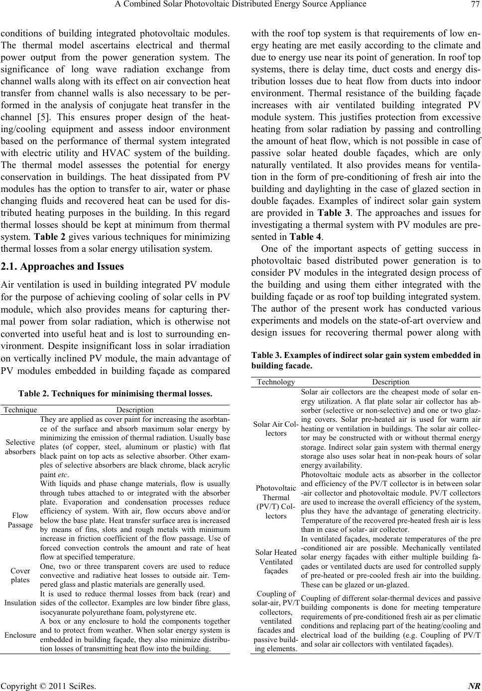 A Combined Solar Photovoltaic Distributed Energy Source Appliance 77 conditions of building integrated photovoltaic modules. The thermal model ascertains electrical and thermal power output from the power generation system. The significance of long wave radiation exchange from channel walls along with its effect on air convection heat transfer from channel walls is also necessary to be per- formed in the analysis of conjugate heat transfer in the channel [5]. This ensures proper design of the heat- ing/cooling equipment and assess indoor environment based on the performance of thermal system integrated with electric utility and HVAC system of the building. The thermal model assesses the potential for energy conservation in buildings. The heat dissipated from PV modules has the option to transfer to air, water or phase changing fluids and recovered heat can be used for dis- tributed heating purposes in the building. In this regard thermal losses should be kept at minimum from thermal system. Table 2 gives various techniques for minimizing thermal losses from a solar energy utilisation system. 2.1. Approaches and Issues Air ventilation is used in building integrated PV module for the purpose of achieving cooling of solar cells in PV module, which also provides means for capturing ther- mal power from solar radiation, which is otherwise not converted into useful heat and is lost to surrounding en- vironment. Despite insignificant loss in solar irradiation on vertically inclined PV module, the main advantage of PV modules embedded in building façade as compared Table 2. Techniques for minimising thermal losses. Technique Description Selective absorbers They are applied as cover paint for increasing the asorbtan- ce of the surface and absorb maximum solar energy by minimizing the emission of thermal radiation. Usually base plates (of copper, steel, aluminum or plastic) with flat black paint on top acts as selective absorber. Other exam- ples of selective absorbers are black chrome, black acrylic paint etc. Flow Passage With liquids and phase change materials, flow is usually through tubes attached to or integrated with the absorbe r plate. Evaporation and condensation processes reduce efficiency of system. With air, flow occurs above and/o r below the base plate. Heat transfer surface area is increased b y means of fins, slots and rough metals with minimum increase in friction coefficient of the flow passage. Use o f forced convection controls the amount and rate of hea t flow at specified temperature. Cover plates One, two or three transparent covers are used to reduce convective and radiative heat losses to outside air. Tem- pered glass and plastic materials are generally used. Insulation It is used to reduce thermal losses from back (rear) and sides of the collector. Examples are low binder fibre glass, isocyanurate polyurethane foam, polystyrene etc. Enclosure A box or any enclosure to hold the components togethe r and to protect from weather. When solar energy system is embedded in building façade, they also minimize distribu- tion losses of transmitting heat flow into the building. with the roof top system is that requirements of low en- ergy heating are met easily according to the climate and due to energy use near its point of generation. In roof top systems, there is delay time, duct costs and energy dis- tribution losses due to heat flow from ducts into indoor environment. Thermal resistance of the building façade increases with air ventilated building integrated PV module system. This justifies protection from excessive heating from solar radiation by passing and controlling the amount of heat flow, which is not possible in case of passive solar heated double façades, which are only naturally ventilated. It also provides means for ventila- tion in the form of pre-conditioning of fresh air into the building and daylighting in the case of glazed section in double façades. Examples of indirect solar gain system are provided in Table 3. The approaches and issues for investigating a thermal system with PV modules are pre- sented in Table 4. One of the important aspects of getting success in photovoltaic based distributed power generation is to consider PV modules in the integrated design process of the building and using them either integrated with the building façade or as roof top building integrated system. The author of the present work has conducted various experiments and models on the state-of-art overview and design issues for recovering thermal power along with Table 3. Examples of indirect solar gain system embedded in building facade. TechnologyDescription Solar Air Col- lectors Solar air collectors are the cheapest mode of solar en- ergy utilization. A flat plate solar air collector has a b - sorber (selective or non-selective) and one or two glaz- ing covers. Solar pre-heated air is used for warm ai r heating or ventilation in buildings. The solar air collec- tor may be constructed with or without thermal energy storage. Indirect solar gain system with thermal energ y storage also uses solar heat in non-peak hours of sola r energy availability. Photovoltaic Thermal (PV/T) Col- lectors Photovoltaic module acts as absorber in the collecto r and efficiency of the PV/T collector is in between sola r -air collector and photovoltaic module. PV/T collectors are used to increase the overall efficiency of the system, plus they have the advantage of generating electricity. Temperature of the recovered pre-heated fresh air is less than in case of solar- air collector. Solar Heated Ventilated façades In ventilated façades, moderate temperatures of the pre -conditioned air are possible. Mechanically ventilate d solar energy façades with either multiple building fa- çades or ventilated ducts are used for controlled supply of pre-heated or pre-cooled fresh air into the building. These can be glazed or un-glazed. Coupling of solar-air, PV/T collectors, ventilated facades and passive build- ing elements. Coupling of different solar-thermal devices and passive building components is done for meeting temperature requirements of pre-conditioned fresh air as per climatic conditions and replacing part of the heating/cooling an d electrical load of the building (e.g. Coupling of PV/T and solar air collectors with ventilated façades). Copyright © 2011 SciRes. NR 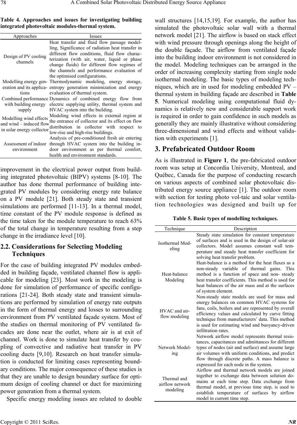 78 A Combined Solar Photovoltaic Distributed Energy Source Appliance Table 4. Approaches and issues for investigating building integrated photovoltaic modules-thermal system. Approaches Issues Design of PV cooling channels Heat transfer and fluid flow passage model- ling, Significance of radiation heat transfer in different flow conditions, fluid flow charac- terization (with air, water, liquid or phase change fluids) for different flow regimes o f the channels and performance evaluation o f the optimised configurations. Modelling energy gen- eration and its applica- tions Thermodynamic modeling, energy storage, entropy generation minimization and energy evaluation of thermal system. Combined performance with building energy supply Dynamics of combined energy flow from electric supplying utility, thermal system and HVAC system into the building. Modelling wind effects and wind – induced flow in solar energy collector Modeling wind effects in external region a t the entrance of collector and its effect on flow distribution in collector with respect to low-rise and high-rise buildings. Assessment of indoor environment Analysis of pre-conditioned fresh air entering through HVAC system into the building in- door environment as per thermal comfort, health and environment standards. improvement in the electrical power output from build- ing integrated photovoltaic (BIPV) systems [8-10]. The author has done thermal performance of building inte- grated PV modules by considering energy rate balance on a PV module [21]. Both steady state and transient simulations are performed [11-13]. In a thermal model, time constant of the PV module response is defined as the time taken for the module temperature to reach 63% of the total change in temperature resulting from a step change in the irradiance level [10]. 2.2. Considerations for Selecting Modeling Techniques For the case of building integrated PV modules embed- ded in building façade, ventilated channel flow is appli- cable for modeling [23]. Most work in the modeling is done for simulation of performance of specific configu- rations [21-24]. Both steady state and transient simula- tions are performed by simulation of energy rate outputs in the form of thermal energy and losses to surrounding environment from PV ventilated façade system. Most of the studies on thermal monitoring of PV ventilated fa- cades are done near the outlet, where air is at exit of channel. Work is done to simulate heat transfer by cou- pling of convective and radiative heat transfer in PV cooling ducts [9,10]. Research on heat transfer simula- tion is conducted for limiting cases representing bound- ary conditions. The major consequence of these studies is that they are unable to design boundary surface for opti- mum design of cooling channel or duct for maximizing power generation from a thermal system. Specific energy modeling issues are related to double wall structures [14,15,19]. For example, the author has simulated the photovoltaic solar wall with a thermal network model [21]. The airflow is based on stack effect with wind pressure through openings along the height of the double façade. The airflow from ventilated façade into the building indoor environment is not considered in the model. Modeling techniques can be arranged in the order of increasing complexity starting from single node isothermal modeling. The basic types of modeling tech- niques, which are in used for modeling embedded PV – thermal system in building façade are described in Table 5. Numerical modeling using computational fluid dy- namics is relatively new and considerable support work is required in order to gain confidence in such models as generally they are mainly illustrative without considering three-dimensional and wind effects and without valida- tion with experiments [1]. 3. Prefabricated Outdoor Room As is illustrated in Figure 1, the pre-fabricated outdoor room was setup at Concordia University, Montreal, and Québec, Canada for the purpose of conducting research on various aspects of combined solar photovoltaic dis- tributed energy source appliance [1]. The outdoor room with section for testing photo vol-taic and solar ventila- tion technologies was designed and built up for Table 5. Basic types of modelling techniques. Technique Description Isothermal Mod- eling Steady state simulation for constant temperature of surfaces and is used in the design of solar-air collectors. Model assumes constant wall tem- perature and steady heat transfer coefficient for solving heat transfer problem. Heat-balance Modeling Heat-balance is a method for the heat fluxes as a non-steady variable of thermal gains. This method is a function of space and non- steady heat transfer coefficients. This method is used for heat balances of the air mass and at the surfaces of system element. HVAC and air- flow modeling Non-steady state models are used for mass and energy balances on common HVAC systems for fans, coils, boilers and are represented by overall efficiency values and calculated by curve fitting technique from manufacturers’ data. This method is used for estimating wind and buoyancy-driven infiltration rates. Network Model- ing Network airflow model represents thermal resis- tances, capacitances and admittances for different types of nodes (air and surface) and assume large air volumes with uniform conditions, and predict flow through discrete paths. A mass balance is expressed for each node in the system. Thermal and airflow network modeling Airflow and thermal network models are joined together to exchange data between solution do- mains at each time step. Data exchange from thermal model, at previous time step, is used to establish temperature of surfaces by airflow model in current time step. C opyright © 2011 SciRes. NR 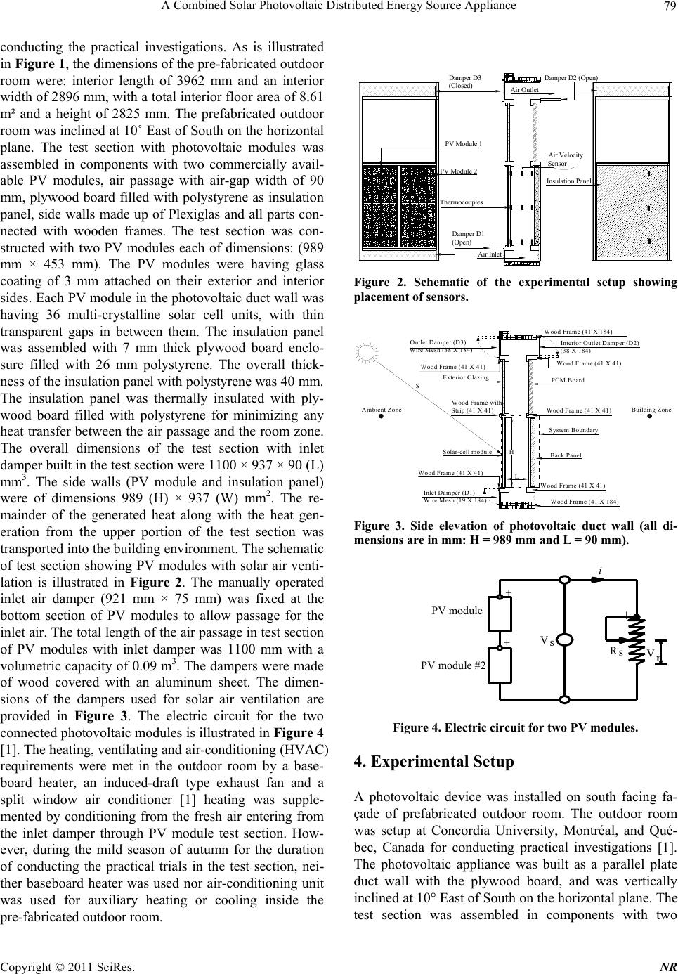 A Combined Solar Photovoltaic Distributed Energy Source Appliance 79 conducting the practical investigations. As is illustrated in Figure 1, the dimensions of the pre-fabricated outdoor room were: interior length of 3962 mm and an interior width of 2896 mm, with a total interior floor area of 8.61 m² and a height of 2825 mm. The prefabricated outdoor room was inclined at 10˚ East of South on the horizontal plane. The test section with photovoltaic modules was assembled in components with two commercially avail- able PV modules, air passage with air-gap width of 90 mm, plywood board filled with polystyrene as insulation panel, side walls made up of Plexiglas and all parts con- nected with wooden frames. The test section was con- structed with two PV modules each of dimensions: (989 mm × 453 mm). The PV modules were having glass coating of 3 mm attached on their exterior and interior sides. Each PV module in the photovoltaic duct wall was having 36 multi-crystalline solar cell units, with thin transparent gaps in between them. The insulation panel was assembled with 7 mm thick plywood board enclo- sure filled with 26 mm polystyrene. The overall thick- ness of the insulation panel with polystyrene was 40 mm. The insulation panel was thermally insulated with ply- wood board filled with polystyrene for minimizing any heat transfer between the air passage and the room zone. The overall dimensions of the test section with inlet damper built in the test section were 1100 × 937 × 90 (L) mm3. The side walls (PV module and insulation panel) were of dimensions 989 (H) × 937 (W) mm2. The re- mainder of the generated heat along with the heat gen- eration from the upper portion of the test section was transported into the building environment. The schematic of test section showing PV modules with solar air venti- lation is illustrated in Figure 2. The manually operated inlet air damper (921 mm × 75 mm) was fixed at the bottom section of PV modules to allow passage for the inlet air. The total length of the air passage in test section of PV modules with inlet damper was 1100 mm with a volumetric capacity of 0.09 m3. The dampers were made of wood covered with an aluminum sheet. The dimen- sions of the dampers used for solar air ventilation are provided in Figure 3. The electric circuit for the two connected photovoltaic modules is illustrated in Figure 4 [1]. The heating, ventilating and air-conditioning (HVAC) requirements were met in the outdoor room by a base- board heater, an induced-draft type exhaust fan and a split window air conditioner [1] heating was supple- mented by conditioning from the fresh air entering from the inlet damper through PV module test section. How- ever, during the mild season of autumn for the duration of conducting the practical trials in the test section, nei- ther baseboard heater was used nor air-conditioning unit was used for auxiliary heating or cooling inside the pre-fabricated outdoor room. Air Inlet Air Outlet Air Velocity Sensor Damper D1 (Open) Damper D3 (Closed) Damper D2 (Open) PV Module 2 Insulation Panel PV Module 1 Thermocouples Figure 2. Schematic of the experimental setup showing placement of sensors. System Boundary Back Panel PCM Board Interior Outlet Damper (D2) (38 X 184) Exterior Glazing Solar-cell module Outlet Damper (D3) Inlet Damper (D1) Wire Mesh (19 X 184) Wood Frame (41 X 184) Wood Frame (41 X 41) Wood Frame (41 X 41) Wood Frame (41 X 41) Wire Mesh (38 X 184) Wood Frame (41 X 184) Wood Frame with Strip (41 X 41) Ambient ZoneBuilding Zone H L Wood Frame (41 X 41) Wood Frame (41 X 41) S Figure 3. Side elevation of photovoltaic duct wall (all di- mensions are in mm: H = 989 mm and L = 90 mm). Figure 4. Electric circuit for two PV modules. 4. Experimental Setup A photovoltaic device was installed on south facing fa- çade of prefabricated outdoor room. The outdoor room was setup at Concordia University, Montréal, and Qué- bec, Canada for conducting practical investigations [1]. The photovoltaic appliance was built as a parallel plate duct wall with the plywood board, and was vertically inclined at 10° East of South on the horizontal plane. The test section was assembled in components with two i V s + V r + PV module PV module #2 +s R Copyright © 2011 SciRes. NR  80 A Combined Solar Photovoltaic Distributed Energy Source Appliance commercially available PV modules, air passage with air-gap width of 90 mm, plywood board filled with poly- styrene as insulation panel, side walls made up of Plexi- glas and all parts connected with wooden frames. The combined solar photovoltaic appliance section was con- structed with two glass coated PV modules each of di- mensions: (989 mm × 453 mm). The PV modules were having glass coating of 3 mm attached on their exterior and interior sides. The plywood board was assembled with 7 mm thick plywood board enclosure filled with 26 mm poly-styrene. The overall thickness of plywood board with polystyrene was 40 mm. The exterior damp- ers were made of wood covered with an aluminum sheet. The heating, ventilating and air-conditioning (HVAC) re- quirements were met in the outdoor room by a baseboard heater, an induced-draft type exhaust fan and a split window air conditioner [1]. The heating was supple- mented by conditioning from the fresh air entering from the inlet damper through photovoltaic duct wall. How- ever, during the mild season of autumn for the duration of conducting experimental runs, neither baseboard heater was used nor air-conditioning unit was used for auxiliary heating or cooling inside the pre-fabricated outdoor room. The pair of PV modules used for conducting experi- mental investigations was connected in series for genera- tion of electric power with a rheostat of maximum vary- ing resistance up to 50Ω. T-type thermocouples were used for obtaining thermal measurements from the test section of photovoltaic module. As is illustrated in Fig- ure 1, three thermocouple sensors were placed at the top, middle and bottom locations in the PV module, air-passage and insulation panel of plywood board filled with polystyrene were used to measure local tempera- tures. Two thermocouples were used to measure the in- side test room air temperature and ambient air tempera- ture. The hybrid air ventilation created for the PV mod- ule test section was by natural wind, or through buoy- ancy effect in the absence of wind [1]. The fan pressure was used to achieve higher air velocities by operation of the exhaust fan fixed on opposite wall with respect to wall of the test Section [1]. The slight negative pressure was induced for drawing low air velocities in absence of wind-induced pressure from the inlet damper into the test section through the test room [1]. Air velocity sensor was placed perpendicular to the walls of the PV module test section to record axial air velocities near its outlet. The thermocouple outputs, currents, voltages, solar irra- diation and air velocity signals were connected to a data logger and a computer for data storage. The measure- ments collected from the sensors were recorded as a function of air velocities or mass flow rate from the test section with use of fan pressure. The experimental data from the data acquisition system was collected and stored every two minutes in the computer [1]. 5. Simulation Model 5.1. Assumptions The assumptions applicable to the simulation model are [1]: i) quasi steady state heat transfer analysis has been performed for a photovoltaic duct wall assuming parallel plate configuration; ii) uniform average air velocity dis- tribution; iii) temperature variation only in y-direction (vertical), being taken as lumped in other directions (x-axis and z-axis); iv) air properties are evaluated at film temperature of 300 K; v) negligible heat transfer from side walls/plywood board and room air zone; vi) conduction (diffusion) equation for performing energy balance on air nodes is not taken into consideration; vii) no infiltration or air leakage sources from the test section; and viii) ambient air and room air temperatures are specified. 5.2. Governing Equations For photovoltaic module of the duct with a steady solar heat flux generation, Poisson’s heat equation with boundary conditions is written as: 22 22 0 p Pp p q TT k xy in 0 p x t 0 y H (1) ap a p p ShT T T xk at (2) 0x , 1 n p pa pipi n p p hTThr TT T xk at p x t (3) For plywood board of duct with insulation, Laplace’s heat equation with boundary conditions is written as: 22 22 0 in 0 ii ppi TT xy Ltx Ltty H (4) ss i i i hT T T xk at p i x Lt t (5) , 1 () ( n ii apiip p i i hT Thr T T T xk ) at p x Lt (6) 5.3. Two Dimensional Energy and Mass Balance Equations The energy balance between convective flux and en- thalpy flux of air with its boundary condition is written as: C opyright © 2011 SciRes. NR  A Combined Solar Photovoltaic Distributed Energy Source Appliance 81 T0 y2 pi aa TT T in 0 y H (7) () () aa Ty Tk at 1 2 H yk n (8) 0( 1)kn p c vLc hW (9) The conjugate heat exchange analysis is performed for a section of photovoltaic duct wall with one PV module and corresponding areas of air passage and insulating plywood board. The finite difference approximations are used to develop algebraic nodal equations for each node in the computational grid. The nodal equations are de- veloped by performing an energy balance on surface and air nodes in the control volume i.e. control volume finite difference method (CVFDM) is used for representing algebraic nodal Equation [1]. The general energy balance equation for ‘p’ surface nodes of PV module is written as [1]: ,1,1 1,1, , ()( ) ()() () oapapyp ppp pp pppapapipi i TTUqATT U TTU TTUUTT 0 ,1 0 0 (10) Similarly, the energy balance equation for ‘i’ surface nodes of insulating plywood board is written as: ,1,11 ,, ()() () () ()0 is isiiiiiiii iaiaipi p p TTU TTUTTU TTUUTT (11) The energy balance equation for ‘a’ air nodes is writ- ten as: ,11 , ()()() aaaaaiaiaap UTT UTTUTT (12) The solution of nodal equations of thermal network comprises formulation of conductance’s matrix and heat source matrix [1]. Matrix equation has heat source vector terms for Q’s and U’s are the conductance terms at vari- ous nodes. The general matrix form of nodal equation is written as [1]: ,, , 11 () NN mn mnmn nn UT Q (13) 6. Results and Discussions 6.1 Temperature Solutions The sample measurement results obtained from section of photovoltaic duct wall are presented in Table 6. The location of sensors as per Figure 1 is presented in Table 7. The measurements that were obtained from experi- mental setup of photovoltaic duct wall are for cases of buoyancy-induced and fan-induced hybrid ventilation. The air temperatures in photovoltaic duct wall are de- veloped as a function of magnitude of the ambient air temperature. The maximum convection heat transfer was observed between the ambient cold air entering into the inlet damper and the air passage of the test section. The dissipation of heat at the inlet opening has resulted in considerable increase in temperature of the air. For the general case fan-induced hybrid ventilation, the tem- perature difference between top and bottom node for PV module was around 2˚C, for insulating plywood board between 8˚C-10˚C and temperature difference between ambient air and air leaving the outlet of photovoltaic duct wall varies between 5-9˚C [1]. The insulating plywood board was heated by long wave radiation heat exchange from PV module and its temperature at top node was ~ 15˚C higher than ambient air and surface temperature difference between top and bottom nodes of the insula- tion panel was ~ 10˚C [1]. The temperature differences were higher for the case of buoyancy-induced hybrid ventilation. Thermal power is easily calculated for vari- ous components of photovoltaic duct wall from the tem- perature differences. The results obtained from two dimensional numerical solutions for Run no. 1 of Table 6 are illustrated from Figure 5(a) to Figure 5(c). The temperature profiles of PV module, air and insulation panel are obtained with respect to the height of photovoltaic duct wall. The initial boundary values in the model are based on the measured values of quasi steady-state solar irradiation, ambient air temperature, and room air temperature and air velocities. The measured boundary values were then used to obtain two dimensional numerical solutions for one dimensional heat equations of the photovoltaic duct wall. The nu- merical results are obtained by assuming constant air and surface properties. The mean air velocity was assumed be constant in the test section for representing nodes of air with same thermal capacity conductance terms, mcp also termed as thermal capacity rate p C through out its height [1]. The amount of dissipated heat from the PV module taken up by air is dependent on mass flow rate passing over it, thermal capacity of air and temperature difference between air-column in the test Section [1]. The dissipated heat from the face area (W × H) of PV module is ventilation heat rate is convection heat loss from the walls of PV module test section due to differ- ence in temperature between the walls of test section and air flowing across cross-sectional area of test section across one PV module [1]. 6.2. Sensible Heat Storage Capacity In Table 8, heat storage capacity has been calculated both for temperature differences in y and x-directions. Thermo-physical properties of various components of photovoltaic duct wall were evaluated at 300 K. Thermo-physical properties of plywood board with insu- Copyright © 2011 SciRes. NR  A Combined Solar Photovoltaic Distributed Energy Source Appliance Copyright © 2011 SciRes. NR 82 lation were obtained from tests conducted with heat flow meter and related specifications from the manufacturer. The temperature differences along y-direction are ob- tained from the two dimensional numerical model. The temperature differences along x-direction are obtained by assuming same temperature difference per unit thickness of material along x and y-directions. The photovoltaic duct wall with wooden frame was composed of non- homogeneous materials having different densities, spe- cific heats and thicknesses. The pair of PV module was having three layers of material viz., a flat sheet of solar cells, with glass face sheets on its exterior and interior sides. The surface temperature of PV module was as- sumed to be uniformly distributed in the three layers. The heat capacity of the wooden frame and sealing mate- rial was having negligible effect on the temperature of PV module, air or insulation panel because wood was Used as construction material and moreover the magni- Table 6. Sample experimental results. Run No. S (Wm−2) Ep (W) To (°C) Ts (°C) V (ms−1) Tp(b) (°C) Tp(m) (°C) Tp(t) (°C) Tb(b) (°C) Tb(m) (°C) Tb(t) (°C) Ta(b) (°C) Ta(m) (°C) Ta(t) (°C) Fan-induced hybrid ventilation 1 725.4 31.1 14.5 22.6 0.425 34.2 32.9 36.3 19.9 24.0 29.4 18.8 19.2 22.4 Buoyancy-induced hybrid ventilation 2 697.5 28.8 13.3 24.9 0.17 39.9 45.0 46.8 28.4 35.0 38.3 21.7 28.3 29.8 Table 7. Location of sensors in the experimental setup. Distance of sensors (Figure 2) Tp(b) (°C) Tp(m) (°C) Tp(t) (°C) Tb(b) (°C) Tb(m) (°C) Tb(t) (°C) Ta(b) (°C) Ta(m) (°C) Ta(t) (°C) Air velocity sensor y (cm) 15 55 94 15 55 94 15 55 94 99 z (cm) 60 60 60 60 60 60 60 60 60 60 x (mm) 6.2 6.2 6.2 96.2 96.2 96.2 51.2 51.2 51.2 51.2 Note: x is horizontal; y is vertical; z is adjacent 3rd axis of x-y plane of Figure 2 Table 7. Location of sensors in the experimental setup. Distance of sensors (Figure 2) Tp(b) (°C) Tp(m) (°C) Tp(t) (°C) Tb(b) (°C) Tb(m) (°C) Tb(t) (°C) Ta(b) (°C) Ta(m) (°C) Ta(t) (°C) Air velocity sensor y (cm) 15 55 94 15 55 94 15 55 94 99 z (cm) 60 60 60 60 60 60 60 60 60 60 x (mm) 6.2 6.2 6.2 96.2 96.2 96.2 51.2 51.2 51.2 51.2 Note: x is horizontal; y is vertical; z is adjacent 3rd axis of x-y plane of Figure 2 Air y = 14.866e 0.0366x R 2 = 0.9944 15 16 17 18 19 20 21 22 4.9514.8524.75 34.65 44.55 54.45 64.35 74.25 84.15 94.05 Height (cm) Temperature ( o C) Insulating plywood Board y = 2.4418Ln(x) + 19.448 R 2 = 0.9942 17 18 19 20 21 22 23 24 25 4.9514.8524.7534.6544.5554.45 64.3574.2584.1594.05 Height (cm) Temperature ( o C) PV Module y = 32.197e 0.0097x R 2 = 0.9743 32 32.5 33 33.5 34 34.5 35 35.5 36 4.9514.85 24.75 34.65 44.55 54.45 64.3574.25 84.15 94.05 Height (cm) Temperature ( o C) (a) (b) (c) Figure 5. Temperature plots with height of photovoltaic duct wall: (a) PV module; (b) Air; (c) Insulating plywood board. 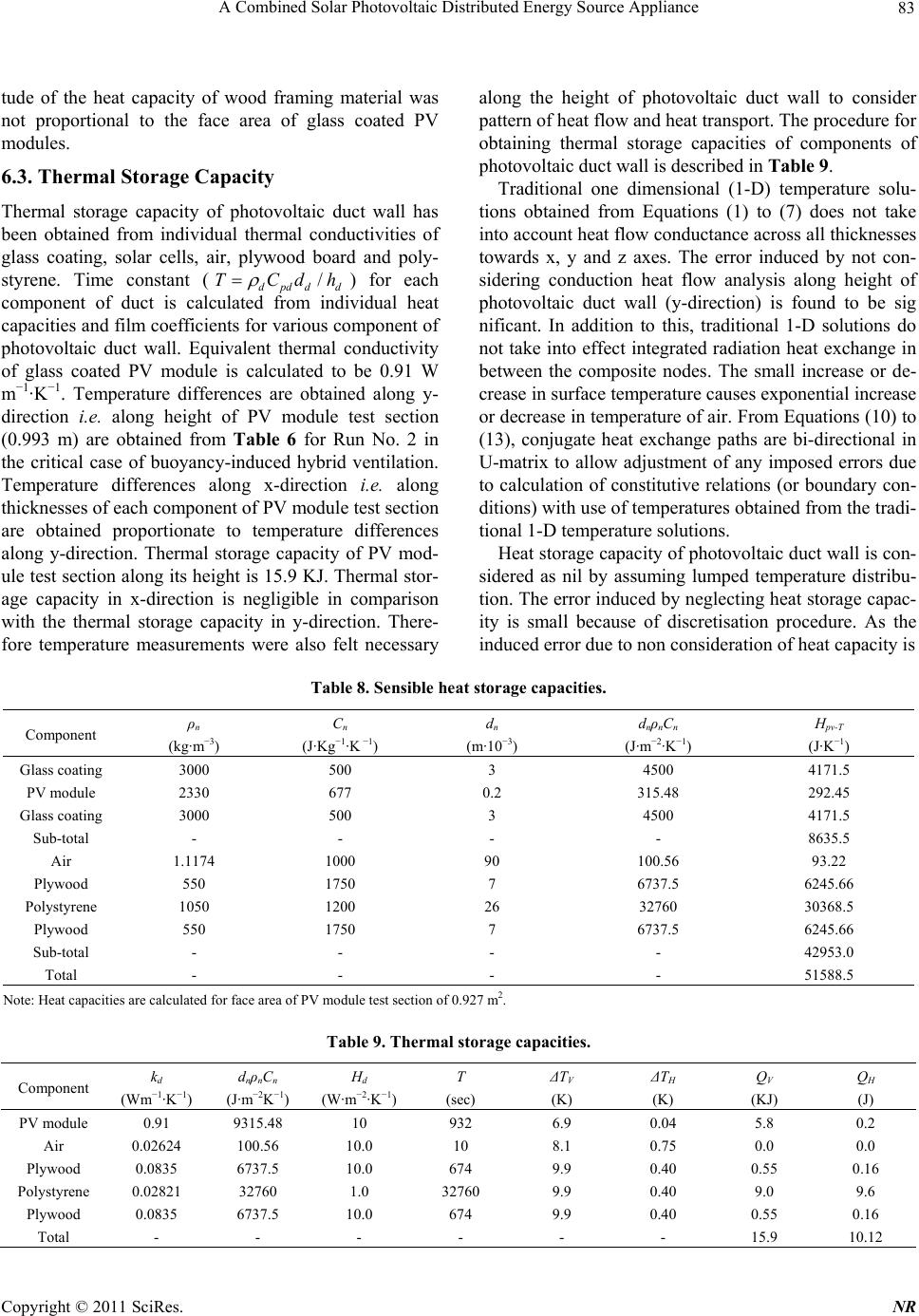 A Combined Solar Photovoltaic Distributed Energy Source Appliance 83 tude of the heat capacity of wood framing material was not proportional to the face area of glass coated PV modules. 6.3. Thermal Storage Capacity Thermal storage capacity of photovoltaic duct wall has been obtained from individual thermal conductivities of glass coating, solar cells, air, plywood board and poly- styrene. Time constant (/ dpdd d TCdh ) for each component of duct is calculated from individual heat capacities and film coefficients for various component of photovoltaic duct wall. Equivalent thermal conductivity of glass coated PV module is calculated to be 0.91 W m−1·K−1. Temperature differences are obtained along y- direction i.e. along height of PV module test section (0.993 m) are obtained from Table 6 for Run No. 2 in the critical case of buoyancy-induced hybrid ventilation. Temperature differences along x-direction i.e. along thicknesses of each component of PV module test section are obtained proportionate to temperature differences along y-direction. Thermal storage capacity of PV mod- ule test section along its height is 15.9 KJ. Thermal stor- age capacity in x-direction is negligible in comparison with the thermal storage capacity in y-direction. There- fore temperature measurements were also felt necessary along the height of photovoltaic duct wall to consider pattern of heat flow and heat transport. The procedure for obtaining thermal storage capacities of components of photovoltaic duct wall is described in Table 9. Traditional one dimensional (1-D) temperature solu- tions obtained from Equations (1) to (7) does not take into account heat flow conductance across all thicknesses towards x, y and z axes. The error induced by not con- sidering conduction heat flow analysis along height of photovoltaic duct wall (y-direction) is found to be sig nificant. In addition to this, traditional 1-D solutions do not take into effect integrated radiation heat exchange in between the composite nodes. The small increase or de- crease in surface temperature causes exponential increase or decrease in temperature of air. From Equations (10) to (13), conjugate heat exchange paths are bi-directional in U-matrix to allow adjustment of any imposed errors due to calculation of constitutive relations (or boundary con- ditions) with use of temperatures obtained from the tradi- tional 1-D temperature solutions. Heat storage capacity of photovoltaic duct wall is con- sidered as nil by assuming lumped temperature distribu- tion. The error induced by neglecting heat storage capac- ity is small because of discretisation procedure. As the induced error due to non consideration of heat capacity is Table 8. Sensible heat storage capacities. Component ρn (kg·m−3) Cn (J·Kg−1·K −1) dn (m·10−3) dnρnCn (J·m−2·K−1) Hpv-T (J·K−1) Glass coating 3000 500 3 4500 4171.5 PV module 2330 677 0.2 315.48 292.45 Glass coating 3000 500 3 4500 4171.5 Sub-total - - - - 8635.5 Air 1.1174 1000 90 100.56 93.22 Plywood 550 1750 7 6737.5 6245.66 Polystyrene 1050 1200 26 32760 30368.5 Plywood 550 1750 7 6737.5 6245.66 Sub-total - - - - 42953.0 Total - - - - 51588.5 Note: Heat capacities are calculated for face area of PV module test section of 0.927 m2. Table 9. Thermal storage capacities. Component kd (Wm−1·K−1) dnρnCn (J·m−2K−1) Hd (W·m−2·K−1) T (sec) ΔTV (K) ΔTH (K) QV (KJ) QH (J) PV module 0.91 9315.48 10 932 6.9 0.04 5.8 0.2 Air 0.02624 100.56 10.0 10 8.1 0.75 0.0 0.0 Plywood 0.0835 6737.5 10.0 674 9.9 0.40 0.55 0.16 Polystyrene 0.02821 32760 1.0 32760 9.9 0.40 9.0 9.6 Plywood 0.0835 6737.5 10.0 674 9.9 0.40 0.55 0.16 Total - - - - - - 15.9 10.12 Copyright © 2011 SciRes. NR 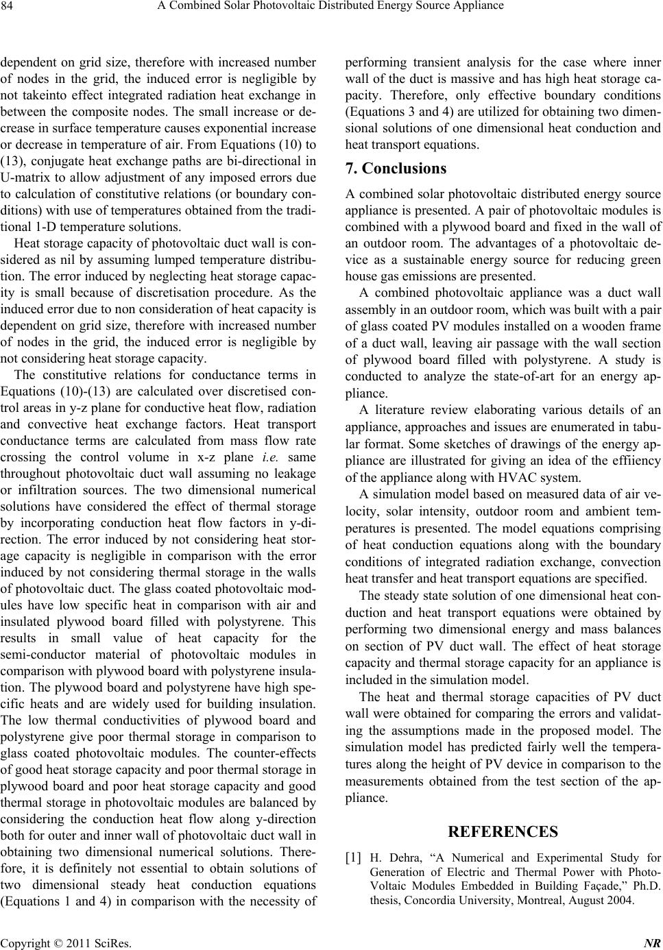 84 A Combined Solar Photovoltaic Distributed Energy Source Appliance dependent on grid size, therefore with increased number of nodes in the grid, the induced error is negligible by not takeinto effect integrated radiation heat exchange in between the composite nodes. The small increase or de- crease in surface temperature causes exponential increase or decrease in temperature of air. From Equations (10) to (13), conjugate heat exchange paths are bi-directional in U-matrix to allow adjustment of any imposed errors due to calculation of constitutive relations (or boundary con- ditions) with use of temperatures obtained from the tradi- tional 1-D temperature solutions. Heat storage capacity of photovoltaic duct wall is con- sidered as nil by assuming lumped temperature distribu- tion. The error induced by neglecting heat storage capac- ity is small because of discretisation procedure. As the induced error due to non consideration of heat capacity is dependent on grid size, therefore with increased number of nodes in the grid, the induced error is negligible by not considering heat storage capacity. The constitutive relations for conductance terms in Equations (10)-(13) are calculated over discretised con- trol areas in y-z plane for conductive heat flow, radiation and convective heat exchange factors. Heat transport conductance terms are calculated from mass flow rate crossing the control volume in x-z plane i.e. same throughout photovoltaic duct wall assuming no leakage or infiltration sources. The two dimensional numerical solutions have considered the effect of thermal storage by incorporating conduction heat flow factors in y-di- rection. The error induced by not considering heat stor- age capacity is negligible in comparison with the error induced by not considering thermal storage in the walls of photovoltaic duct. The glass coated photovoltaic mod- ules have low specific heat in comparison with air and insulated plywood board filled with polystyrene. This results in small value of heat capacity for the semi-conductor material of photovoltaic modules in comparison with plywood board with polystyrene insula- tion. The plywood board and polystyrene have high spe- cific heats and are widely used for building insulation. The low thermal conductivities of plywood board and polystyrene give poor thermal storage in comparison to glass coated photovoltaic modules. The counter-effects of good heat storage capacity and poor thermal storage in plywood board and poor heat storage capacity and good thermal storage in photovoltaic modules are balanced by considering the conduction heat flow along y-direction both for outer and inner wall of photovoltaic duct wall in obtaining two dimensional numerical solutions. There- fore, it is definitely not essential to obtain solutions of two dimensional steady heat conduction equations (Equations 1 and 4) in comparison with the necessity of performing transient analysis for the case where inner wall of the duct is massive and has high heat storage ca- pacity. Therefore, only effective boundary conditions (Equations 3 and 4) are utilized for obtaining two dimen- sional solutions of one dimensional heat conduction and heat transport equations. 7. Conclusions A combined solar photovoltaic distributed energy source appliance is presented. A pair of photovoltaic modules is combined with a plywood board and fixed in the wall of an outdoor room. The advantages of a photovoltaic de- vice as a sustainable energy source for reducing green house gas emissions are presented. A combined photovoltaic appliance was a duct wall assembly in an outdoor room, which was built with a pair of glass coated PV modules installed on a wooden frame of a duct wall, leaving air passage with the wall section of plywood board filled with polystyrene. A study is conducted to analyze the state-of-art for an energy ap- pliance. A literature review elaborating various details of an appliance, approaches and issues are enumerated in tabu- lar format. Some sketches of drawings of the energy ap- pliance are illustrated for giving an idea of the effiiency of the appliance along with HVAC system. A simulation model based on measured data of air ve- locity, solar intensity, outdoor room and ambient tem- peratures is presented. The model equations comprising of heat conduction equations along with the boundary conditions of integrated radiation exchange, convection heat transfer and heat transport equations are specified. The steady state solution of one dimensional heat con- duction and heat transport equations were obtained by performing two dimensional energy and mass balances on section of PV duct wall. The effect of heat storage capacity and thermal storage capacity for an appliance is included in the simulation model. The heat and thermal storage capacities of PV duct wall were obtained for comparing the errors and validat- ing the assumptions made in the proposed model. The simulation model has predicted fairly well the tempera- tures along the height of PV device in comparison to the measurements obtained from the test section of the ap- pliance. REFERENCES [1] H. Dehra, “A Numerical and Experimental Study for Generation of Electric and Thermal Power with Photo- Voltaic Modules Embedded in Building Façade,” Ph.D. thesis, Concordia University, Montreal, August 2004. C opyright © 2011 SciRes. NR  A Combined Solar Photovoltaic Distributed Energy Source Appliance 85 [2] H. Dehra, “Mathematical Analysis of a Solar Thermosy- phon,” International conference on Advances in Energy Research, Bombay, December 2007, p. 6. [3] H. Dehra, “A 1-D/2-D Model for an Exterior HVAC Rec- tangular Duct with a Steady Solar Heat Flux generation,” The proceedings of the Second International Green En- ergy Conference, Oshawa, 25-29 June 2006, pp. 1240-1251. [4] H. Dehra, “The Integration of Photovoltaic and Solar Ven- tilation Technologies into a Pre-Fabricated Outdoor Room,” An industry poster presented at proceedings of CIM Mining Conference & Exhibition, Montreal, 29 April -2 May 2007, pp. 424-431. [5] H. Dehra, “On Solar Building Energy Devices,” The 18th IASTED International Conference on Modeling and Simulation, Montreal 30 May-1 June 2007, pp. 96-101. [6] H. Dehra, “A Heat Transmission Model for a Telephone Line,” 21st Canadian Congress of Applied Mechanics, Ryerson University, Toronto, 3-7 June 2007, pp. 356-357. [7] H. Dehra, “The Study of a Solar Cell Device under Illu- mination,” 21st Canadian Congress of Applied Mechanics, Department of Mechanical & Industrial Engineering, Ry- erson University, Toronto, 3-7 June 2007, pp. 354-355. [8] H. Dehra, “The Electrodynamics of A Pair of PV Modules with Connected Building Resistance,” The 3rd IASME/WSEAS International Conference on energy, en- vironment, ecosystems and sustainable development, Agios Nikolaos, Crete Island, 24-26 July 2007, pp. 562-565. [9] H. Dehra, “Ventilation Materials Characterisation of a Solar Panel Duct Wall,” International Conference on Ad- vances and Trends in Engineering Materials and their Applications, Montréal, 6-10 August 2007, p. 537. [10] H. Dehra, “The Effect of Heat and Thermal Storage Ca- pacities ff Photovoltaic Duct Wall on Co-Generation of Electric and Thermal Power,” The Proceedings of Ameri- Can Institute of Chemical Engineers, Houston, 22-26 April 2007. [11] H. Dehra, “A Unified Theory for Stresses and Oscil La- tions,” Canadian Acoustical Associa-tion (CAA) Confer- ence, Concordia University, Montréal, 9-12 October 2007, pp.132-133. [12] H. Dehra, “The Entropy Matrix Generated Exergy Model For A Photovoltaic Heat Exchanger Under Critical Oper- ating Conditions,” International Journal of Exergy, Vol. 5, No. 2, 2008, pp. 132-149. [13] H. Dehra, “An Integrated Approach for Designing and Optimizing Building Environment for Delhi Climate,” M.Tech project thesis report, School of Energy and Envi- ronmental Studies, Devi Ahilya Vishwavidyalaya, Indore, Madhya Pradesh, India, May 1997. [14] H. Dehra, “Power Transfer and Inductance in A Star Connected 3-Phase RC Circuit Amplifier,” Proceedings AIChE 2008 Spring National Meeting, New Orleans, 6-10 April 2008. [15] H Dehra, “A guide for signal processing of sensors and transducers,” Proceedings AIChE 2009 Spring National Meeting, Tampa, 27-30 April 2009, Session 96a. [16] H. Dehra, “A Benchmark Solution for Interference of Noise Waves,” Proceedings AIChE 2009 Spring Na- tional Meeting, Tampa, 27-30 April 2009, session 67c. [17] H. Dehra, “A Monitoring Model for a Fan Operated Photovoltaic Hybrid Air Ventilation System,” Proceed- ings AIChE 2010 Spring National Meeting, San Antonio, 21-25 March 2010, session 143b. [18] H. Dehra, “Experiments on Photovoltaic Modules Em- bedded in Building Facade,” Proceedings AIChE 2010 Spring National Meeting, San Antonio, 21-25 March 2010, session 38b. [19] H. Dehra, “Solar Energy Absorbers,” Sciyo publication, 2010, pp. 111-134. [20] H. Dehra, “The Noise Scales and Their Units,” Canadian Acoustics, Vol. 36, No. 3, 2008, pp. 78-79. [21] H. Dehra, “A Two Dimensional Thermal Network Model for a Photovoltaic Solar Wall,” Solar Energy, Vol. 83, No. 11, 2009, pp. 1933-1942. [22] H. Dehra, “Acoustic Filters,” Proceedings National Con- ference on Renewable Energy (NaCORE 2009), Jodhpur, 5-7 November 2009, pp. 164-168. [23] H. Dehra, “A Building Integrated Photovoltaic Airflow Window System,” Proceedings 2nd International Con- ference and Exhibition on Advances in Energy Research, Indian Institute of Technology, Bombay, 9-11 December 2009. [24] H. Dehra, “A Design Tool for an Outdoor Duct”, Pro- ceedings 9th International Conference on Sustainable En- ergy Technologies (SET 2010), Shanghai Jiao Tong Uni- versity School of Medicine, Shanghai, 24-27 August 2010. Copyright © 2011 SciRes. NR  86 A Combined Solar Photovoltaic Distributed Energy Source Appliance Nomenclature ∆Tm,n Temperature difference at node m,n (K) A Face area of PV module (m2) cp Specific heat of air at constant pressure (J·kg−1·K−1) Ep Electric power generated H Height of photovoltaic duct wall (m) ha Ambient heat transfer coefficient (W·m−2·K−1) hi Convective heat transfer coefficient for insulating plywood board (W·m−2·K−1) hc Average convective heat transfer coefficient (W·m−2·K−1) hp Convective heat transfer coefficient for PV module (W·m−2·K−1) hr Linearised radiation heat transfer coefficient (W·m−2·K−1) hs Film coefficient for the insulating plywood board facing room air zone (W·m−2·K−1) L Air gap width of duct (m) m Steady mass flow rate (kg·s−1) n Number of discretised elements in y-ordinate N Total number of discretised elements in grid Qm,n Heat source term at the node (m,n) S Incident solar intensity (W·m−2) Up,i Conductance between nodes p and i (direction p to i) (W·K−1) Um,n Conductance Term at node (m,n), Sp Absorbed solar radiation by PV module (Watts) Tm,n Temperature matrix for discretised nodes (m·X·n) Ta Temperature variable for the air (K) Ti Temperature variable for the insulating board (K) ti Thickness of Back panel (m) To Ambient air temperature (K) Tp Temperature variable for the PV module (K) tp Thickness of PV module (m) Ts Room air temperature (K) v Air velocity (m·s−1) W Width (m) Subscripts p PV module i Insulating plywood board a Air m Position of row in U-matrix n Position of column in U-matrix o Ambient air s Room C opyright © 2011 SciRes. NR |