

Paper Menu >>
Journal Menu >>
 Intelligent Control and Automation, 2011, 2, 160-166 doi:10.4236/ica.2011.22019 Published Online May 2011 (http://www.SciRP.org/journal/ica) Copyright © 2011 SciRes. ICA LQG Control Design for Balancing an Inverted Pendulum Mobile Robot Ragnar Eide, Per Magne Egelid, Alexander Stamsø, Hamid Reza Karimi Department o f En g i neer i n g , Faculty of Engineering and Science, University of Agder, Grimstad, Norway E-mail: [email protected] Received December 26, 2011; revised May 17, 2011; acce pted May 19, 2011 Abstract The objective of this paper is to design linear quadratic controllers for a system with an inverted pendulum on a mobile robot. To this goal, it has to be determined which control strategy delivers better performance with respect to pendulum’s angle and the robot’s position. The inverted pendulum represents a challenging control problem, since it continually moves toward an uncontrolled state. Simulation study has been done in MATLAB Simulink environment shows that both LQR and LQG are capable to control this system success- fully. The result shows, however, that LQR produced better response compared to a LQG strategy. Keywords: LQG Control, Inverted Pendulum, Mobile Robot 1. Introduction Inverted pendulum has been the subject of numerous studies in automatic control since the forties. The in- verted pendulum is a typical representative of a class of high-order nonlinear and non-minimum phase systems [1]. Since the system is inherently nonlinear, it is useful to illustrate some of the ideas in nonlinear control. Wheeled mobile robots have in the recent years become increasingly important in industry, since they provide a large degree of flexibility and efficiency with respect to transportation, inspection, and operation. In many cases, however, it is the control, or lack of knowledge in control, which limit the area of applicatio n . In this system, an inverted pendulum is attached to a robot equipped with a motor that drives it along a horizontal track (robot will in the following mean an autonomous robot provided with the Robotics Starter Kit from National Instruments). The user is able to dictate the position and velocity of the robot through the motor. The pendulum is characterized by an unstable equi- librium point, and its behavior can be used in the analysis and stability control of many similar systems. Many different control methods are proposed for the inverted pendulum problem. The Proportional-Integral- Derivative (PID) and Proportional-Derivative (PD) controllers [2] and [3], Model Predictive Control (MPC) [4], and fuzzy contr ol [5] to mentio n a few. How ever one of the obstacles by using the PID and PD controllers are that they alone cannot effectively control all of the pendulum state variables (modes) since they are of lower order than the pendulum itself. Hence, they are usually replaced by a full-order controller [3]. A linear state feedback controller based on the linearized inverted pendulum model can instead be used, and may also be extended with a disturbance observer (Kalman filter) to improve the disturbance rejection performance. The proposed method is to balance an inverted pen- dulum placed on top of a mobile robot by use of LQR/ LQG control methods. Our solution implements an LQG controller with comparison to a simple LQR controller. The controller found by means of a more analytical approach will be tested with implementation of the controller in the MATLAB/Simulink environment. With varying input forces the goal is to design a controller capable of meeting the following requirements: settling time, s T, less than 5 seconds maximum overshoot of 10 degrees (0.175 radians) rise time T less than 0.5 s r We will in part one describe a simplified mathematical model of the problem. Then, when having a state space model of the system, we can in part two go on and determine the controllers and observers. Finally, the results from simulations will then be presented and compared in part three. 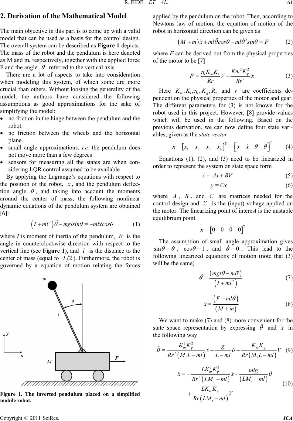 R. EIDE ET AL.161 2. Derivation of the Mathema tical Mode l The main objective in this part is to come up with a valid model that can be used as a basis for the control design. The overall system can be described as Figure 1 depicts. The mass of the robot and the pendulum is here denoted as M and m, respectively, together with the applied force F and the angle referred to the vertical axis. There are a lot of aspects to take into consideration when modeling this system, of which some are more crucial than others. W ithout loosing the generality of the model, the authors have considered the following assumptions as good approximations for the sake of simplifying the model: no friction in the hinge between the pendulum and the robot no friction between the wheels and the horizontal plane small angle approximations, i.e. the pendulum does not move more than a few degrees sensors for measuring all the states are when con- sidering LQR control assumed to be available By applying the Lagrange’s equations with respect to the position of the robot, x , and the pendulum deflec- tion angle , and taking into account the moments around the center of mass, the following nonlinear dynamic equations of the pendulum system are obtained [6]: 2= I mlmglsin mlxcos (1) where I is moment of inertia of the pendulum, is the angle in counterclockwise direction with respect to the vertical line (see Figure 1), and is the distance to th e center of mass (equal to l 2L). Furthermore, the robot is governed by a equation of motion relating the forces Figure 1. The inverted pendulum placed on a simplified mobile robot. applied by the pendulum on the robot. Then, according to Newtons law of motion, the equation of motion of the robot in horizontal direction can be given as 2= M mx mlcosmlsinF (2) where F can be derived out from the physical properties of the motor to be [7] 22 2 =g tmtKm K KK F V Rr Rr x (3) Here ,,, ,, mttg K KKR and are coefficients de- pendent on th e physical properties of th e motor and gear . The different parameters for (3) is not known for the robot used in this project. However, [8] provide values which will be used in the following. Based on the previous derivation, we can now define four state vari- ables, given as the state vector r T T 1234 ==xxxx xx x (4) Equations (1), (2), and (3) need to be linearized in order to represent the system on state space form = x Ax BV (5) = y Cx (6) where A , , and are matrices needed for the control design and is the (input) voltage applied on the motor. The linearizing point of interest is the unstable equilibrium point BC V T =0000x The assumption of small angle approximation gives sin = , cos =1 , and . This lead to the following linearized equations of motion (note that (3) will be the same) =0 2 =mgl mlx Iml (7) = F ml x M m (8) We want to make (7) and (8) more convenient for the state space representation by expressing and x in the following way 22 2 =mg mg t t KK KK g x V Lml RrMLml RrM Lml (9) 22 2 = mg t t mg t LK Kmlg xx LM ml Rr LMml LK KV Rr LMml (10) Copyright © 2011 SciRes. ICA 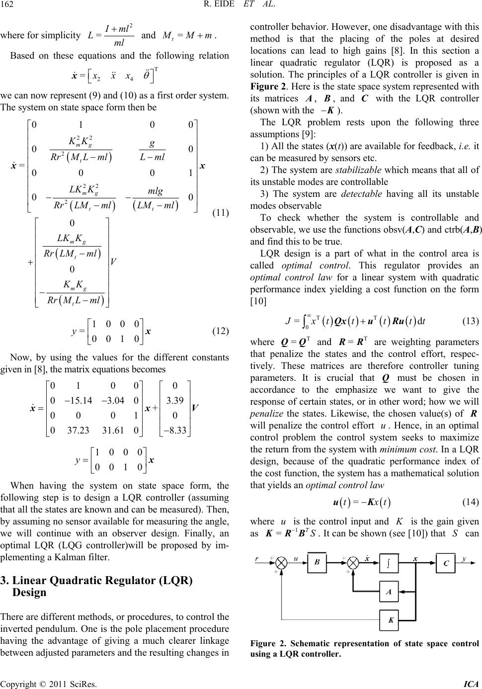 R. EIDE ET AL. 162 where for simplicity 2 = I ml Lml and = t M Mm . Based on these equations and the following relation T 24 =xxx x we can now represenfirst The system on state sen be t (9) and (10) as a order system. pace form th 22 2 22 2 01 00 00 00 0 0 mg mg t t mg t mg t KK g LK Kmlg LM ml Rr LMml LK K Rr LMmlV KK RrMLml (11) (12) Now, by using the values for the different constants given in [8], the matrix equations becomes When having the system on state space form, the following step is to design a LQR controller (assuming that all the states are known and can be measured). Then, by assuming no sensor available for msuring the angle, we will continue with an observer dsign. Finally, an op placement procedure nkage es in covior. However, one disadvantage with this ethod is that the placing of the poles at desired =00 01 tLm l RrM Lml xx 1000 =0010 y x 01 000 0 15.14 3.040 00 010 xx 3.39 + V 037.2331.61 08.33 1000 0010 y x ea e timal LQR (LQG controller)will be proposed by im- plementing a Kalman filter. 3. Linear Quadratic Regulator (LQR) Design There are different methods, or procedures, to control the nverted pendulum. One is the pole i having the advantage of giving a much clearer li between adjusted parameters and the resulting ch ang ntroller beha m locations can lead to high gains [8]. In this section a linear quadratic regulator (LQR) is proposed as a solution. The principles of a LQR controller is given in Figure 2. Here is the state space system represented with its matrices A , B, and C with the LQR controller (shown with the K ). The LQR problem rests upon the following three assumptions [9]: 1) All the states (x(t)) are available for feedback, i.e. it can be measured by sensors etc. 2) The system a stabiliz ble which means that all of its unstable modee cont re a s arrollable bsv(A,C) and ctrb(A,B) an the control area is ca for a linear system with quadratic pe 3) The system are detectable having all its unstable modes observable To check whether the system is controllable and observable, we use the functions o d find this to be true. LQR design is a part of what in lled optimal control. This regulator provides an optimal control law rformance index yielding a cost function on the form [10] T T 0 =d J xt tttt Qxu Ru (13) where T =QQ and T =RR are weighting parameters that penalize the states and the control effort, respec- tively. These matrices are therefore controller tuning parame ters. nce to se of certain e the st It is cru must be chosen in accorda the want responr word; i cial that emphasize we states, or in Q otheto give the how we will penaliz ates. Likewise, the chosen value(s) of R will penalize the control effort u. Hence, in an optimal control problem the control system seeks to maximize the return from the system with mnimum cost. In a LQR design, because of the quadratic performance index of the cost function, the system has a mathe matical solution that yields an optimal control law =txtuK (14) where u is the control input and K is the gain given as 1 =TS K RB . It can be shown (see [10]) that S can Figure 2. Schematic representation of state space control using a LQR controller. Copyright © 2011 SciRes. ICA 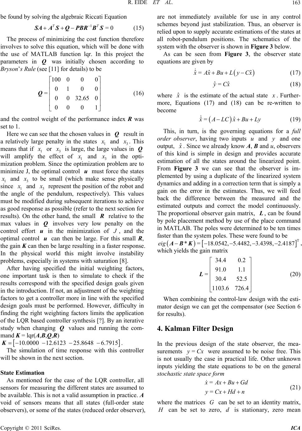 R. EIDE ET AL.163 be found by solving the algebraic Riccati Equation (15) The process of minimizing the cost function therefore involves to solve this equation, which will be done with the use of MATLAB function lqr. In this project the parameters in was initially chosen according to 1=0 TT SAA SQPBRBS Q Bryson’s Rule (see [11] for details) to be 100 000 01 0 0 =0032.650 Q 00 0 1 and the control weight of the performance index R was set to 1. Here we can see that the chosen values in Q result in a relatively large penalty in the states (16) 1 x and 3 x . This means that if 1 x or 3 x e effect is large, the will amplify ofe largvalues in Q th 1 x and 3 x in the opti- n problem are to mization proble.he izat minimize J, the optim contm m Since t al optim rol io ust forc u e the states 1 x and 3 x to be small (which makesysically sene ph since 1 x and 3 x represent the position of the robot and the angle of the pendulum ha ,ectively). Tha respis vlues must be modified during subsequent iterations to achieve as good response as possible (refer to thext section for results). On the other nd, the small e n R relative to t max values in Q involves vy lowenalty on the control effort u in the minimization of he er p J , and the optimal control u can then be rge. For this small R, e gain Kcan then be large resulting in a faster response. In thephysical world this might involve instability problems, especially in systems with saturation [8]. After having specified the initial weighting factors, one important task is then to simulate to check if the results correspond with the specified dign goals given in the introduction If not, an ad justment o f the weigh ting factors to get a controller more in line with te specified design goals must be performed. However, difficulty in finding the right weighting factors limits the application of the LQR based controller synthesis [?]. By an iterative study when changing Q values and running the la th es .h com- mand K = lqr(A,B,Q,R) 10.0000 12.6123 25.8648 6.7915 K. The simulation of time response with this controller will be shown in the next section. State Estimation As mentioned for the case of the LQR controller, all sensors for measuring the different states are assumed to be available. This is not valid assumption in practice. A are not immediately avai a void of sensors means that all states (full-order state observers), or some of the states (reduced order observer), lable for use in any control schemes beyond just stabilization. Thus, an observer is re e schematics of the stem with the observer is shown in Figure 3 below. from Figure 3, the observer state eq lied upon to supply accurate estimations of the states at all robot-pendulum positions. Th syAs can be seen uations are g i v en by ˆˆ ˆ = x AxBuL yCx (17) ˆˆ =yCx (18) where ˆ x is the estimate of the actual state x . Further- more, Equations (17) and (18) can be re-written to become ˆˆ = x ALCxBuLy (19) This, in turn, is the governing equations for a full order observer, having two inputs u and y and one output, ˆ x . Since we already know and servers of this ki is simple in design a estimation of all the states around t From 3 we can se difference between the mea estimauts and correct the mde Th A, B nd o u, ob nd Figure ted outp provides accurate he linearized point. e that the observer is im- plemented by using a duplicate of the linearized system dynamics and adding in a correction term that is simply a gain on the error in the estimates. Thus, we will feed back the sured and the l continuously. e proportional observer gain matrix, L , can be found by pole placement method by use of e placecommand in MATLAB. The poles were determined to be ten times faster than the system poles. These were found to be T *=18.0542, 5.4482, 3.4398, 2.4187eig ABK, which yields the gain matrix 34.4 0.2 91.0 1.1 =30.4 52.5 1103.6 726.4 th L (20) When combining the control-law design with the esti- mator design we can get the compensator (see Section 6 for results). 4. Kalman Filter Desig n In the previous design of the state observer, the mea- surements = y Cx is not usually the case in were assumed to be practical li inputs yielding the state equations to be on the general stochastic state space form noise free. This fe. Other unknown = = x AxBu Gd yCxHdn (21) where the matrices can be set to an identity matrix, G H can be set toro, is stationary, zero mean zed Copyright © 2011 SciRes. ICA 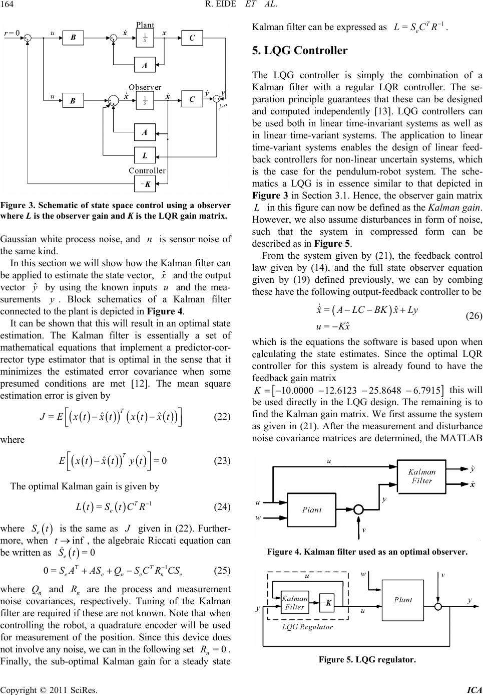 R. EIDE ET AL. 164 Figure 3. Schematic of state space control using a observer where L is the observer gain and K is the LQR gain matrix. Gaussian white process noise, and is sensor noise of the same kind. In this section we will show how the Kalman filter can be applied to estimate the state vector, n ˆ x uand the output vector by using the known inputs and the mea- sureme . Block schematics of a Kalman filter connected to the plant is depicted in Figure 4. It can be shown that this will result in an optimal state estimation. The Kalman filter is essentially a set of inimizes the estimated error covariance when some . is given by ˆ y nts y mathematical equations that implement a predictor-cor- rector type estimator that is optimal in the sense that it m presumed conditions are met [12]The mean square estimation error ˆˆ =T J Ext xtxt xt (22) where T ˆ=0Ext xtyt (23) The optimal Kalman gain is given by 1 =T e LtS tCR (24) where e St is the same as J given in (22). Further- more, when inft, the alge T braic Riccati equation can be written 1 e (25) and are the process and measurement noise cnpectively. Tuning red if these are not known. Note that when coer will be used for me the position. Since this device does not involv ancan in the fo mal Kalman gain for as =0 e St 0= T eenen SAASQSCR CS where n Q ovaria filter are requi easurem e Finally, the sub-opti n R ces, res nt of y noise, we of the Kalman ntrolling the robot, a quadrature encod llowing set =0 n R. a steady state Kalman filter can be expressed as 1 =T e LSCR . 5. LQG Controller The LQG controller is simply the combi ar feed ot system. The sche- atics a LQG is in essence similar to that depicted in nce, the observer gain matrix in this figure can now be defined as the Kalman gain. nation of a Kalman filter with a regular LQR controller. The se- paration principle guarantees that these can be designed and computed independently [13]. LQG controllers can be used both in linear time-invariant systems as well as in linear time-variant systems. The application to linear time-variant systems enables the design of line- back controllers for non-linear uncertain systems, which is the case for the pendulum-rob m Figure 3 in Section 3.1. He L However, we also assume disturbances in form of noise, such that the system in compressed form can be described as in Figure 5. From the system given by (21), the feedback control law given by (14), and the full state observer equation given by (19) defined previously, we can by combing these have the following output-feedback co ntr oller to be ˆˆ = ˆ = x ALCBKxLy uKx (26) which is the equations the software is based upon when lculating the state estimates. Since the optimal LQR controller for this system is already found to have the feedback gain matrix ca 10.0000 12.6123K 25.8648 6.7915 be this will used directly in the LQG design. The remaining is to find the Kalman gain matrix. We first assume the system as given in (21). After the measurement and disturbance noise covariance matrices are determined, the MATLAB Figure 4. Kalman filter used as an optimal observer. Figure 5. LQG regulator. Copyright © 2011 SciRes. ICA 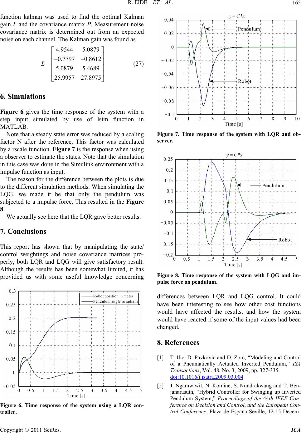 R. EIDE ET AL.165 function kalman was used to find the optimal Kalman gain L and the covariance matrix P. Measurement noise covariance matrix is determined out from an expected noise on each channel. The Kalman gain was found as (27 6. Simulations Figure 6 gives the time response of the system with a step input simulated by use of lsim function in MATLAB. Note that a steady state error was reduced by a scalin The reason for the difference between the plots is due to the different simulation methods. When simulating the LQG, we made it be that only the subjected to a impulse force. This resulted in the Figure 8. We actually see here that the LQR gave better results. 4.95445.0879 0.7797 0.8612 = 25.9957 27.8975 L 5.0879 5.4689 ) g factor N after twas calculated by a rscale function. Figure 7 is the response when u sin g a observer to estimate the states. Note that the simulation in this case was done in the Simulink environment with a impulse function as input. he reference. This factor pendulum was . Conclusions 7 This report has shown that by manipulating the state/ control weightings and noise covariance matrices pro- perly, both LQR and LQG will give satisfactory result. Although the results has been somewhat limited, it has provided us with some useful knowledge concerning Figure 6. Time response of the system using a LQR con- troller. Figure 7. Time response of the system with LQR and ob- server. Figure 8. Time response of the system with LQG and im- ulse force on pendulum. differences between LQR and LQG control. It could have been interesting to see how other cost functions would have affected the results, and how the system would have reacted if some of the input values had been changed. 8. References [1] T. Ilic, D. Pavkovic and D. Zorc, “Modeling and Control of a Pneumatically Actuated Inverted Pendulum,” ISA Transactions, Vol. 48, No. 3, 2009, pp. 327-335. doi:10.1016/j.isatra.2009.03.004 p [2] J. Ngamwiwit, N. Komine, S. Nundrakwang and T. Ben- janarasuth, “Hybrid Controller for Swinging up Inverted Pendulum System,” Proceedings of the 44th IEEE Con- -ference on Decision and Control, and the European Con trol Conference, Plaza de España Seville, 12-15 Decem- Copyright © 2011 SciRes. ICA 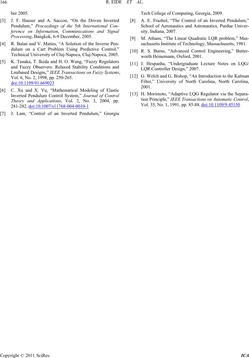 R. EIDE ET AL. Copyright © 2011 SciRes. ICA 166 ] J. F. Hauser and A. Saccon, “On the Driven Inverted ical University of Cluj-Napoca, Cluj-Napoca, 2005. Ikeda and H. O. Wang, “Fuzzy Regulators servers: Relaxed Stability Conditions and ber 2005. [3 Pendulum,” Proceedings of the 5th International Con- ference on Information, Communications and Signal Processing, Bangkok, 6-9 December, 2005. [4] R. Balan and V. Maties, “A Solution of the Inverse Pen- dulum on a Cart Problem Using Predictive Control,” Techn [5] K. Tanaka, T. and Fuzzy Ob Lmibased Designs,” IEEE Transactions on Fuzzy Systems, Vol. 6, No. 2, 1998, pp. 250-265. doi:10.1109/91.669023 [6] C. Xu and X. Yu, “Mathematical Modeling of Elastic Inverted Pendulum Control System,” Journal of Control Theory and Applications, Vol. 2, No. 3, 2004, pp. 281-282. doi:10.1007/s11768-004-0010-1 [7] J. Lam, “Control of an Inverted Pendulum,” Georgia Tech College of Computing, Georgia, 2009. [8] A. E. Frazhol, “The Control of an Inverted Pendulum,” School of Aeronautics and Astronautics, Purdue Univer- sity, Indiana, 2007. [9] M. Athans, “The Linear Quadratic LQR problem,” Mas- sachusetts Institute of Technology, Massachusetts, 1981. [10] R. S. Burns, “Advanced Control Engineering,” Butter- worth Heinemann, Oxford, 2001. [11] J. Hespanha, “Undergraduate Lecture Notes on LQG/ LQR Controller Design,” 2007. [12] G. Welch and G. Bishop, “An Introduction to the Kalman Filter,” University of North Carolina, North Carolina, 2001. [13] H. Morimoto, “Adaptive LQG Regulator via the Separa- tion Principle,” IEEE Transactions on Automatic Control, Vol. 35, No. 1, 1991, pp. 85-88. doi:10.1109/9.45150 |