

Paper Menu >>
Journal Menu >>
 Engineering, 2011, 3, 549-554 doi:10.4236/eng.2011.34064 Published Online May 2011 (http://www.SciRP.org/journal/eng) Copyright © 2011 SciRes. ENG Delamination in Fiber Reinforced Plastics: A Finite Element Approach P. K. Rakesh*, V. Sharma, I. Singh, D. Kumar Department of Mechanical and Industrial Engineering, Indian Institute of Technology Roorkee, Roorkee, India E-mail: [email protected] Received December 29, 2010; revised January 13, 2011; accepted April 19, 2011 Abstract The fiber reinforced plastics (FRPs) are being used widely in the most diverse applications ranging from the aerospace to the sports goods industry. Drilling in particular is important to facilitate the assembly operations of structurally intricate composite products. The drilling of holes in FRPs leads to drilling induced damage which is an important research area. The researchers worldwide have tried to minimize the damage by opti- mizing the operating variables, and tool designs as well as by developing unconventional methods of hole making. Most of the work done so far has been experimental in nature with little or no focus on numerical simulation of the drilling behavior of FRPs. In the present research endeavor, a finite element model has been developed to investigate the drilling induced damage of FRP laminates. Keywords: Drilling, Delamination, Finite Element Analysis 1. Introduction The fiber reinforced plastics offers many advantages over traditional materials such as high strength to weight ratios, flexibility in design, dimensional stability, corrosion resistance [1-2]. Drilling of FRPs is often required to ascertain the structural integrity of complex products. Delamination is a major problem associated with the drilling of FRPs. Apart from reducing the structural integrity of the materials; delamination also results in poor assembly tolerance and has the potential to cause long term performance deterioration. During drilling, many factors affect machinability; the impor- tant factors are machining parameters such as cutting speed, feed rate, and the drill diameter, as well as the drill point geometry. The drilling induced damage not only affects the quality of the hole but also so metimes results in-service performance deterioration. It has been found that drill- ing induced damage can be reduced by modifying the drill point geometry and optimizing the process pa- rameters [3-5]. Drilling induced damage depends on the cutting speed and feed rate for different drill point ge- ometries (4-facet, 8-facet, and Jo drill), and the damage area around the drilled hole increases with an increase in the cutting speed/feed rate [6]. It was concluded that the drilling-induced damage in case of the Jo drill is mini mum as comp ared to oth er drills . Mathew et al. [7] studied the influence of using a Trepanning tool on thrust force and torque while drilling glass fiber rein- forced plastic (GFRP) composites. The investigation showed that the performance of the Trepanning tool was superior to the conventional Twist drill. A number of research endeavors [8-15] have been undertaken to investigate and develop optimum tool point geometry for drilling holes in FRPs composites, but still a lot re- mains to be done. Failure mechanisms in composites include four types of failure modes: fiber fracture, fiber buckling and kinking, matrix cracking under transverse tension and shearing, and matrix crushing under trans- verse compression and shearing [16]. Budan and Vijayarangan [17] studied the FE analysis of drilling process to predict the effects of the drilling parameters and fiber volume fraction on the surface finish, hole quality and delamination. The failure envelope gave a clear idea of the damage zone resulting due to the drill- ing operation. Durao et al. [18] developed a cohesive damage model in order to simulate the thrust force and delamination onset during drilling of CFRP composites. The FE model was validated with the analytical model based on linear elastic fracture mechanics (LEFM). Zitoune and Collomet [19] proposed a numerical FE method to calculate the thrust force responsible for the defect at the exit of the hole during drilling in CFRP 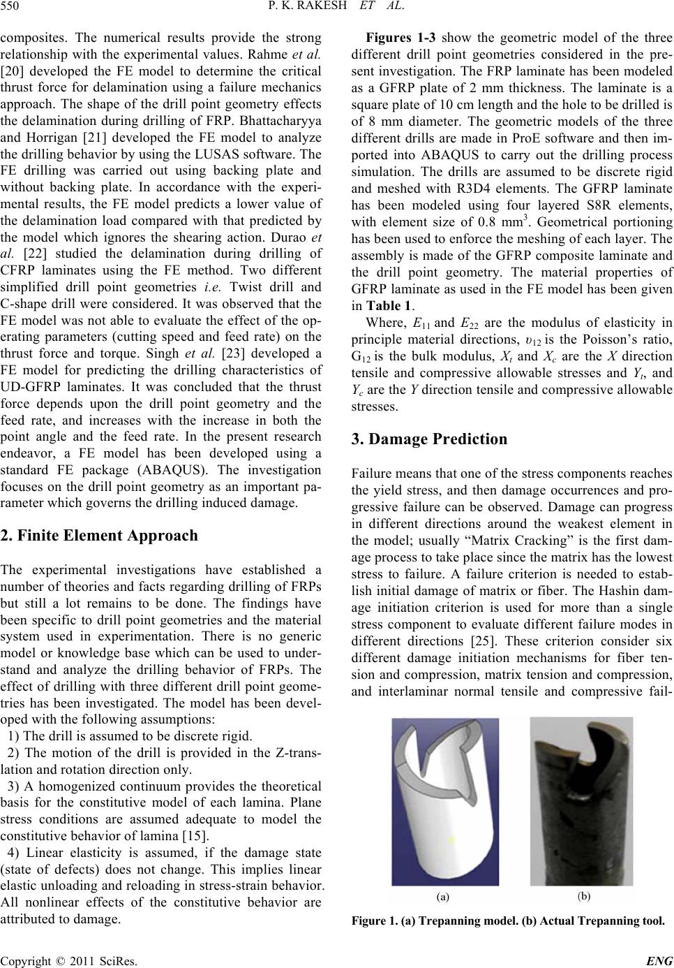 P. K. RAKESH ET AL. 550 composites. The numerical results provide the strong relationship with the experimental values. Rahme et al. [20] developed the FE model to determine the critical thrust force for delamination using a failure mechanics approach. The shape of the drill point geometry effects the delamination during drilling of FRP. Bhattacharyya and Horrigan [21] developed the FE model to analyze the drilling behavior by using the LUSAS software. The FE drilling was carried out using backing plate and without backing plate. In accordance with the experi- mental results, the FE model predicts a lower value of the delamination load compared with that predicted by the model which ignores the shearing action. Durao et al. [22] studied the delamination during drilling of CFRP laminates using the FE method. Two different simplified drill point geometries i.e. Twist drill and C-shape drill were considered. It was observed that the FE model was not able to evaluate the effect of the op- erating parameters (cutting speed and feed rate) on the thrust force and torque. Singh et al. [23] developed a FE model for predicting the drilling characteristics of UD-GFRP laminates. It was concluded that the thrust force depends upon the drill point geometry and the feed rate, and increases with the increase in both the point angle and the feed rate. In the present research endeavor, a FE model has been developed using a standard FE package (ABAQUS). The investigation focuses on the drill point geometry as an important pa- rameter which governs the drilling induced damage. 2. Finite Element Approach The experimental investigations have established a number of theories and facts regarding drilling of FRPs but still a lot remains to be done. The findings have been specific to drill point geometries and the material system used in experimentation. There is no generic model or knowledge base which can be used to under- stand and analyze the drilling behavior of FRPs. The effect of drilling with three different drill point geome- tries has been investigated. The model has been devel- oped with the following assumptions: 1) The drill is assumed to be discrete r igid. 2) The motion of the drill is provided in the Z-trans- lation and rotation direction only. 3) A homogenized continuum provides the theoretical basis for the constitutive model of each lamina. Plane stress conditions are assumed adequate to model the constitutive behavior of lamina [15]. 4) Linear elasticity is assumed, if the damage state (state of defects) does not change. This implies linear elastic unloading and reloading in stress-strain behavior. All nonlinear effects of the constitutive behavior are attr ibu ted to da mag e . Figures 1-3 show the geometric model of the three different drill point geometries considered in the pre- sent investigation. The FRP laminate has been modeled as a GFRP plate of 2 mm thickness. The laminate is a square plate of 10 cm length and the hole to be drilled is of 8 mm diameter. The geometric models of the three different drills are made in ProE software and then im- ported into ABAQUS to carry out the drilling process simulation. The drills are assumed to be discrete rigid and meshed with R3D4 elements. The GFRP laminate has been modeled using four layered S8R elements, with element size of 0.8 mm3. Geometrical portioning has been used to enforce the meshing of each layer. The assembly is made of the GFRP composite laminate and the drill point geometry. The material properties of GFRP laminate as used in the FE model has been given in Table 1. Where, E11 and E22 are the modulus of elasticity in principle material directions, υ12 is the Poisson’s ratio, G12 is the bulk modulus, Xt and Xc are the X direction tensile and compressive allowable stresses and Yt, and Yc are the Y direction tensile and compressive allowable stresses. 3. Damage Prediction Failure means that one of the stress components reaches the yield stress, and then damage occurrences and pro- gressive failure can be observed. Damage can progress in different directions around the weakest element in the model; usually “Matrix Cracking” is the first dam- age proces s to take p lac e s in ce th e ma tr ix h as th e low es t stress to failure. A failure criterion is needed to estab- lish initial damage of matrix or fiber. The Hashin dam- age initiation criterion is used for more than a single stress component to evaluate different failure modes in different directions [25]. These criterion consider six different damage initiation mechanisms for fiber ten- sion and compression, matrix tension and compression, and interlaminar normal tensile and compressive fail- Figure 1. (a) Trepanning model. (b) Actual Trepanning tool. Copyright © 2011 SciRes. ENG 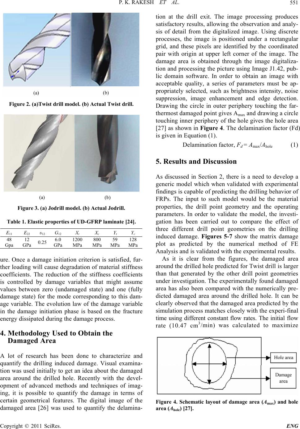 P. K. RAKESH ET AL.551 Figure 2. (a)Twist drill model. (b) Actual Twist drill. Figure 3. (a) Jodrill model. (b) Actual Jodrill. Table 1. Elastic properties of UD-GFRP laminate [24]. E11 E22 υ12 G12 Xt X c Y t Y c 48 Gpa 12 GPa 0.25 6.0 GPa 1200 MPa 800 MPa 59 MPa 128 MPa ure. Once a damage initiation criterion is satisfied, fur- ther loading will cause degradation of material stiffness coefficients. The reduction of the stiffness coefficients is controlled by damage variables that might assume values between zero (undamaged state) and one (fully damage state) for the mode corresponding to this dam- age variable. The evolution law of the damage variable in the damage initiation phase is based on the fracture energy dissipated during the damage process. 4. Methodology Used to Obtain the Damaged Area A lot of research has been done to characterize and quantify the drilling induced damage. Visual examina- tion was used initially to get an idea about the damaged area around the drilled hole. Recently with the devel- opment of advanced methods and techniques of imag- ing, it is possible to quantify the damage in terms of certain geometrical features. The digital image of the damaged area [26] was used to quantify the delamina- tion at the drill exit. The image processing produces satisfactory results, allowing the observation and analy- sis of detail from the digitalized image. Using discrete processes, the image is positioned under a rectangular grid, and these pixels are identified by the coordinated pair with origin at upper left corner of the image. The damage area is obtained through the image digitaliza- tion and processing the picture using Image J1.42, pub- lic domain software. In order to obtain an image with acceptable quality, a series of parameters must be ap- propriately selected, such as brightness intensity, noise suppression, image enhancement and edge detection. Drawing the circle in outer periphery touching the far- thermost damaged point gives Amax and drawing a circle touching inner periphery of th e hole gives the hole area [27] as shown in Figure 4. The delamination factor (Fd) is given in Equation (1). Delamination factor, Fd = Amax/Ahole (1) 5. Results and Discussion As discussed in Section 2, there is a need to develop a generic model which when validated with experimental findings is capable of predicting the drilling behavior of FRPs. The input to such model would be the material properties, the drill point geometry and the operating parameters. In order to validate the model, the investi- gation has been carried out to compare the effect of three different drill point geometries on the drilling induced damage. Figures 5-7 show the matrix damage plot as predicted by the numerical method of FE Analysis and is validated with the experimental results. As it is clear from the figures, the damaged area around the drilled hole predicted for Twist drill is larger than that generated by the other drill point geometries under investigation. The experimentally found damaged area has also been compared with the numerically pre- dicted damaged area around the drilled hole. It can be clearly observed that the damaged area predicted by the simulation process matches closely with the experi-final time using different constant flow rates. The initial flow rate (10.47 cm3/min) was calculated to maximize Figure 4. Schematic layout of damage area (Amax) and hole area (Ahole) [27]. Copyright © 2011 SciRes. ENG 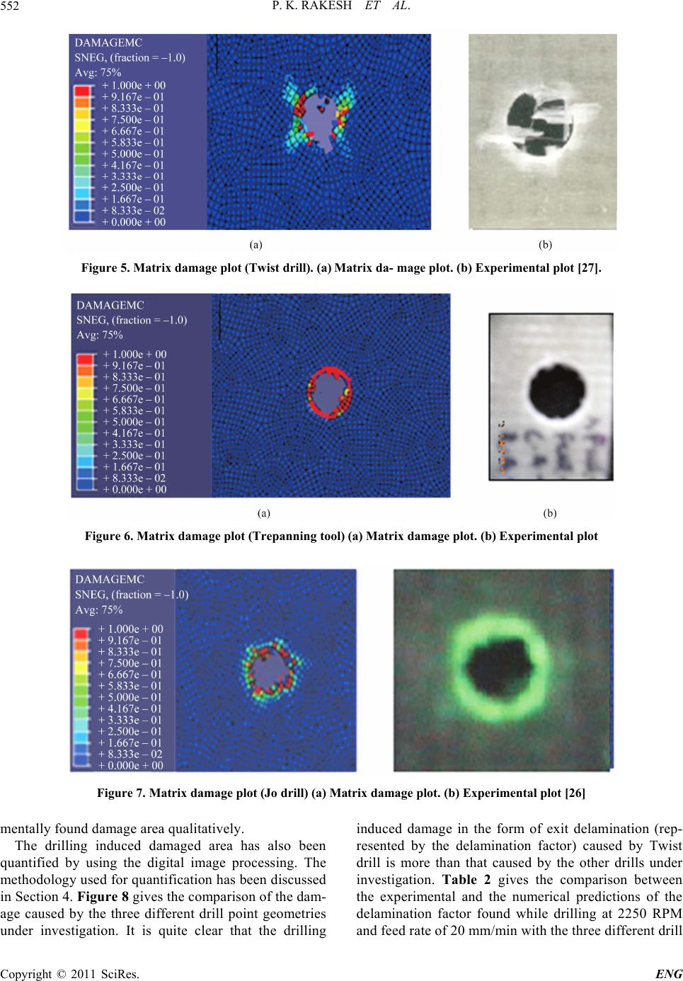 P. K. RAKESH ET AL. Copyright © 2011 SciRes. ENG 552 Figure 5. Matrix damage plot (Twist drill). (a) Matrix da- mage plot. (b) Experimental plot [27]. Figure 6. Matrix damage plot (Trepanning tool) (a) Matrix damage plot. (b) Experimental plot Figure 7. Matrix damage plot (Jo drill) (a) Matrix damage plot. (b) Experimental plot [26] mentally found damage area qualitatively. The drilling induced damaged area has also been quantified by using the digital image processing. The methodology used for quantification has been discussed in Section 4. Figure 8 gives the comparison of the dam- age caused by the three different drill point geometries under investigation. It is quite clear that the drilling induced damage in the form of exit delamination (rep- resented by the delamination factor) caused by Twist drill is more than that caused by the other drills under investigation. Table 2 gives the comparison between the experimental and the numerical predictions of the delamination factor found while drilling at 2250 RPM and feed rate of 20 mm/min with the three different drill 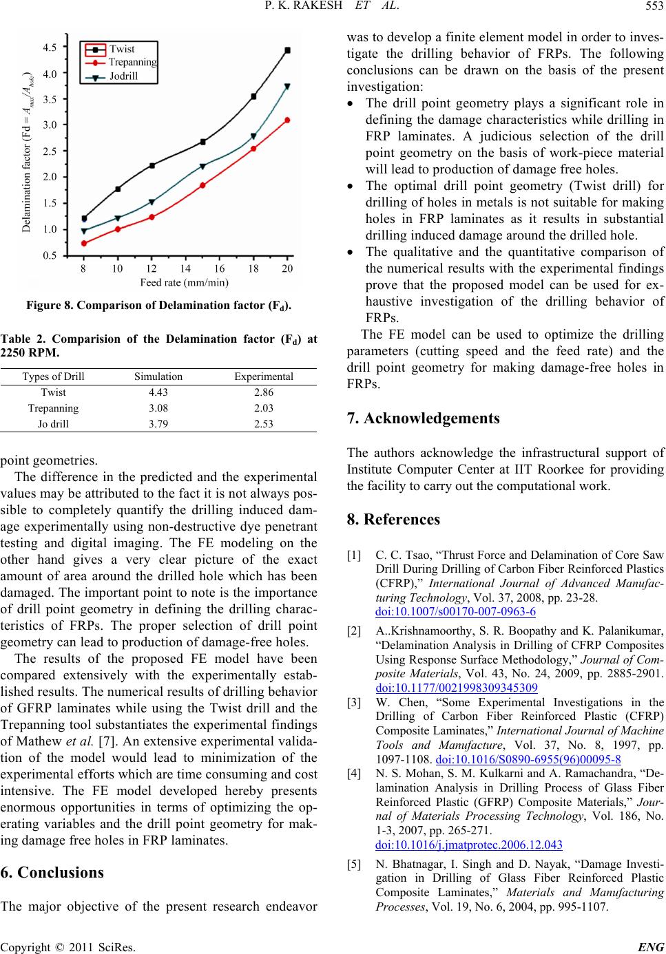 P. K. RAKESH ET AL.553 Figure 8. Comparison of Delamination factor (Fd). Table 2. Comparision of the Delamination factor (Fd) at 2250 RPM. Types of Drill Simulation Experimental Twist 4.43 2.86 Trepanning 3.08 2.03 Jo drill 3.79 2.53 poin t g e o me tries. The difference in the predicted and the experimental value s may b e attr ibuted to th e fact i t is not a lways pos- sible to completely quantify the drilling induced dam- age experimentally using non-destructive dye penetrant testing and digital imaging. The FE modeling on the other hand gives a very clear picture of the exact amount of area around the drilled hole which has been damaged. The important point to note is the importance of drill point geometry in defining the drilling charac- teristics of FRPs. The proper selection of drill point geometry can lead to production of damage-free holes. The results of the proposed FE model have been compared extensively with the experimentally estab- lished results. The numerical results of drilling behavior of GFRP laminates while using the Twist drill and the Trepanning tool substantiates the experimental findings of Mathew et al. [7]. An extensive experimental valida- tion of the model would lead to minimization of the experimental efforts which are time consuming and cost intensive. The FE model developed hereby presents enormous opportunities in terms of optimizing the op- erating variables and the drill point geometry for mak- ing damage free holes in FRP laminates. 6. Conclusions The major objective of the present research endeavor was to de ve lop a fin ite el emen t mo del in ord er to in ves- tigate the drilling behavior of FRPs. The following conclusions can be drawn on the basis of the present investigation : The drill point geometry plays a significant role in defining the damage characteristics while drilling in FRP laminates. A judicious selection of the drill point geometry on the basis of work-piece material will lead to production of damage free holes. The optimal drill point geometry (Twist drill) for drilling of holes in metals is not suitable for making holes in FRP laminates as it results in substantial drilling induced damage around the drilled hole. The qualitative and the quantitative comparison of the numerical results with the experimental findings prove that the proposed model can be used for ex- haustive investigation of the drilling behavior of FRPs. The FE model can be used to optimize the drilling parameters (cutting speed and the feed rate) and the drill point geometry for making damage-free holes in FRPs. 7. Acknowledgements The authors acknowledge the infrastructural support of Institute Computer Center at IIT Roorkee for providing the facility to carry out the computational wo rk. 8. References [1] C. C. Tsao, “Thrust Force and Delamination of Core Saw Drill During Drilling of Carbon Fiber Reinforced Plastics (CFRP),” International Journal of Advanced Manufac- turing Technology, Vol. 37, 2008, pp. 23-28. doi:10.1007/s00170-007-0963-6 [2] A..Krishnamoorthy, S. R. Boopathy and K. Palanikumar, “Delamination Analysis in Drilling of CFRP Composites Using Response Surface Methodology,” Journal of Com- posite Materials, Vol. 43, No. 24, 2009, pp. 2885-2901. doi:10.1177/0021998309345309 [3] W. Chen, “Some Experimental Investigations in the Drilling of Carbon Fiber Reinforced Plastic (CFRP) Composite Laminates,” International Journal of Machine Tools and Manufacture, Vol. 37, No. 8, 1997, pp. 1097-1108. doi:10.1016/S0890-6955(96)00095-8 [4] N. S. Mohan, S. M. Kulkarni and A. Ramachandra, “De- lamination Analysis in Drilling Process of Glass Fiber Reinforced Plastic (GFRP) Composite Materials,” Jour- nal of Materials Processing Technology, Vol. 186, No. 1-3, 2007, pp. 265-271. doi:10.1016/j.jmatprotec.2006.12.043 [5] N. Bhatnagar, I. Singh and D. Nayak, “Damage Investi- gation in Drilling of Glass Fiber Reinforced Plastic Composite Laminates,” Materials and Manufacturing Processes, Vol. 19, No. 6, 2004, pp. 995-1107. Copyright © 2011 SciRes. ENG  P. K. RAKESH ET AL. Copyright © 2011 SciRes. ENG 554 doi:10.1081/AMP-200034486 [6] I. Singh and N. Bhatnagar, “Drilling of Uni-Directional Glass Fiber Reinforced Plastic (UD-GFRP) Composite Laminates,” International Journal of Advanced Manu- facturing Technology, Vol. 27, No. 9-10, 2006, pp. 870-876. doi:10.1007/s00170-004-2280-7 [7] J. Mathew, N. Ramakrishnan and N. K. Naik, “Trepan- ning on Unidirectional Composites,” Composites Part A, Vol. 30, No. 8, 1999, pp. 951-959. doi:10.1016/S1359-835X(99)00012-3 [8] S. C. Lin and J. M. Shen, “Drilling Unidirectional Glass Fiber Reinforced Composite Materials at High Speed,” Journal of Composite Materials, Vol. 33, No. 9, 1999, pp. 827-851.doi:10.1177/002199839903300903 [9] R. Piquet, B. Ferret, F. Lachaud and P. Swider, “Experi- mental Analysis of Drilling Damage in Thin Car- bon/Epoxy Plate Using Special Drill,” Composites Part A, Vol. 31, No. 10, 2000, pp. 1107-1115. doi:10.1016/S1359-835X(00)00069-5 [10] A. M. Abrao, P. E. Faria, J. C. C. Rubio, P. Reis, J. P. Davim, “Drilling of Fiber Reinforced Plastics: A Re- view,” Journal of Materials Processing Technology, Vol. 186, No. 1-3, 2007, pp. 1-7. doi:10.1016/j.jmatprotec.2006.11.146 [11] E. Kilickap, “Optimization of Cutting Parameters on Delamination Based on Taguchi Method during Drilling of GFRP Composite,” Expert Systems with Applications, Vol. 37, No. 8, 2010, pp. 6116-6122. doi:10.1016/j.eswa.2010.02.023 [12] L. M. P. Durão, D. J. S. Gonçalves, J. M. R. S. Tavares, V. H. C. Albuquerque, A. A. Vieira, A. T. Marques, “Drilling Tool Geometry Evaluation for Reinforced Composite Laminates,” Composite Structures, Vol. 92, No. 7, 2010, pp. 1545-1550. doi:10.1016/j.compstruct.2009.10.035 [13] A. Velayudham and R. Krishnamurthy, “Effect of Point Geometry and Their Influence on Thrust and Delamina- tion in Drilling of Polymeric Composites,” Journal of Materials Processing Technology, Vol. 185, No. 1-3, 2007, pp. 204-209. doi:10.1016/j.jmatprotec.2006.03.146 [14] C. C. Tsao, “Investigation into the Effects of Drilling Parameters on Delamination by Various Step-Core Drills,” International Journal of Materials and Product Technology, Vol. 206, No. 1-3, 2008, pp. 405-411. doi:10.1016/j.jmatprotec.2007.12.057 [15] A. Matzenmiller, J. Lubliner and R. L. Taylor, “A Con- stitutive Model for Anisotropic Damage in Fi- ber-Composites,” Mechanics of Materials, Vol. 20, 1995, pp. 125-152. doi:10.1016/0167-6636(94)00053-0 [16] D. Arola and M. Ramulu, “Orthogonal Cutting of Fi- ber-Reinforced Composites: A Finite Element Analysis,” International Journal of Mechanical Sciences, Vol. 39, No. 5, 1997, pp. 597-613. doi:10.1016/S0020-7403(96)00061-6 [17] D. A. Budan and S. Vijayarangan, “Quality Assessment and Delamination Force Evaluation in Drilling of Glass Fiber Reinforced Plastic Laminates—A Finite Element Analysis and Linear Elastic Fracture Mechanics Ap- proach,” Proceedings of the Institution of Mechanical Engineers Part B—Journal of Engineering Manufacture, Vol. 216, 2002, pp. 173-182. [18] L. M. P. Durao, M. F. S. F. de Moura and A. T. Marques, “Numerical Simulation of the Drilling Process on Car- bon/Epoxy Composite Laminates,” Composites Part A, Vol. 37, No. 9, 2006, pp. 1325-1333. doi:10.1016/j.compositesa.2005.08.013 [19] Z. Redouane and C. Francis, “Numerical Prediction of the Thrust Force Responsible of Delaminate During the Drilling of the Long-Fiber Composite Structures,” Com- posites: Part A, Vol. 38, 2007, pp. 858-866. [20] R. Rahme, Y. Landon, F. Lachaud, R. Piquet and P. La- garrigue, “Analytical Model for Composite Laminates Drilling,” International Journal of Advanced Manufac- turing Technology, Vol. 52, No. 5-8, 2010, pp. 609-917. doi:10.1007/s00170-010-2773-5 [21] D. Bhattacharya and D. P. W. Horrigan, “A Study of Hole Drilling in Kevlar Composites,” Composites Science and Technology, Vol. 58, No. 2, 1998, pp. 267-283. doi:10.1016/S0266-3538(97)00127-9 [22] L. M. P. Durao, M. F. S. F. De-Moura and A. T. Marques, “Numerical Prediction of Delamination Onset in Car- bon/Epoxy Composites Drilling,” Engineering Fracture Mechanics, Vol. 75, No. 9, 2008, pp. 2767-2778. doi:10.1016/j.engfracmech.2007.03.009 [23] I. Singh, N. Bhatnagar and P. Viswanath, “Drilling of Uni-Directional Glass Fiber Reinforced Plastics: Experi- mental and Finite Element Study,” Materials & Design, Vol. 29, No. 2, 2008, pp. 546-553. doi:10.1016/j.matdes.2007.01.029 [24] P. K. Rakesh, I. Singh and D. Kumar, “Failure Prediction in Glass Fiber Reinforced Plastic Laminates with Drilled Hole Under Uniaxial Loading,” Materials & Design, Vol. 31, No. 6, 2010, pp. 3002-3007. doi:10.1016/j.matdes.2010.01.022 [25] Z. Hashin, “Failure Criteria for Unidirectional Fiber Composites,” Journal of Applied Mechanics, Vol. 47, No. 2, 1980, pp. 329-334. doi:10.1115/1.3153664 [26] I. Singh and N. Bhatnagar, “Drilling Induced Damage in Uni-Directional Glass Fiber Reinforced Plastic (UD-GFRP) Composite Laminates,” International Jour- nal of Advanced Manufacturing Technology, Vol. 27, No. 9-10, 2006, pp. 877-882. doi:10.1007/s00170-004-2282-5 [27] J. C. Rubio, A. M. Abrao, P. E. Faria, A. E. Correia, J. P. Davim, “Effects of High Speed in the Drilling of Glass Fiber Reinforced Plastic: Evaluation of the Delamination Factor,” International Journal of Machine Tools and Manufacture, Vol. 48, No. 6, 2008, pp. 715-720. doi:10.1016/j.ijmachtools.2007.10.015 |