

Paper Menu >>
Journal Menu >>
 Energy and Power Engineering, 2011, 3, 144-149 doi:10.4236/epe.2011.32018 Published Online May 2011 (http://www.SciRP.org/journal/epe) Copyright © 2011 SciRes. EPE A Cell Model to Describe and Optimize Heat and Mass Transfer in Contact Heat Exchangers Vadim Mizonov1, Nickolay Yelin2, Piotr Yakimychev2 1Ivanovo State Power Engineering University, Ivanovo, Russia 2Ivanovo State University of Architecture and Civil Engineering, Ivanovo, Russia E-mail: [email protected] Received February 28, 2011; revised March 29, 2011; accepted April 2, 2011 Abstract A cell model to describe and optimize heat and mass transfer in contact heat exchangers for utilization of exhaust gases heat is proposed. The model is based on the theory of Markov chains and allows calculating heat and mass transfer at local moving force of the processes in each cell. The total process is presented as two parallel chains of cells (one for water flow and one for gas flow). The corresponding cells of the chains can exchange heat and mass, and water and gas can travel along their chains according to their transition ma- trices. The results of numerical experiments showed that the most part of heat transfer occurs due to moisture condensation from gas and the most intense heat transfer goes near the inlet of gas. Experimental validation of the model showed a good correlation between calculated and experimental data for an industrial contact heat exchanger if appropriate empirical equations were used to calculate heat and mass transfer coefficient. It was also shown that there exists the optimum height of heat exchanger that gave the maximum gain in heat energy utilization. Keywords: Direct Contact Heat Exchanger, Heat and Mass Transfer, Condensation, State Vector, Transition Matrix, Optimization 1. Introduction Contact heat exchangers are widely used in different industries for different technological purposes connected with heat and mass transfer. Therefore, different aspects of their experimental investigation, mathematical mod- eling and optimization can be found in literature. It can be seen even from titles of the papers on the problem in question recently published in various journals [1-7]. The objective of the present study is to model and optimize the process in a contact heat exchanger from the view- point of using them to utilize heat of exhaust gases with high moisture content. It can be a process of contact heating water by combustion products of natural gas, by exhaust air-vapor flow in processes of fabrics treatment in textile industry, and so on. All papers on the problem can be roughly subdivided into three groups. The first one deals with fundamentals of the local heat and mass transfer though a contact surface. The results obtained here are very important but can hardly be directly used for the engineering calculation of the process. The sec- ond group deals with experimental investigation and mathematical description of total heat and mass balances in an apparatus. Within this approach, heat and mass flux is calculated for average difference of transfer potential: average temperature difference, and average vapor par- tial pressure difference. The heat and mass transfer coef- ficients are also calculated for some average parameters of the interacting media. In this case, these coefficients are sooner calibrating parameters of such models than the real characteristics of heat and mass transfer. It is obvious that the approach is very easy and convenient for engineering calculation but it can hardly be used when the process parameters go out of the range that was used to obtain experimental correlations. This approach is fully represented in the book [8] where a lot of data on the exchangers design, experimental investigations and their generalization on the basis of total balances is pre- sented. At last, the third group of researches deals with process simulation on the basis of local heat, mass and momentum balances, i.e., with differential equations of the process. However, these equations are not always easy to solve-particularly if stochastic components of media motion are taken into account when the equations 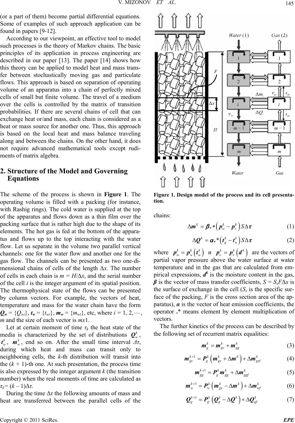 V. MIZONOV ET AL. 145 (or a part of them) become partial differential equations. Some of examples of such approach application can be found in papers [9-12]. According to our viewpoint, an effective tool to model such processes is the theory of Markov chains. The basic principles of its application in process engineering are described in our paper [13]. The paper [14] shows how this theory can be applied to model heat and mass trans- fer between stochastically moving gas and particulate flows. This approach is based on separation of operating volume of an apparatus into a chain of perfectly mixed cells of small but finite volume. The travel of a medium over the cells is controlled by the matrix of transition probabilities. If there are several chains of cell that can exchange heat or/and mass, each chain is considered as a heat or mass source for another one. Thus, this approach is based on the local heat and mass balance traveling along and between the chains. On the other hand, it does not require advanced mathematical tools except rudi- ments of matrix algebra. 2. Structure of the Model and Governing Equations The scheme of the process is shown in Figure 1. The operating volume is filled with a packing (for instance, with Rashig rings). The cold water is supplied at the top of the apparatus and flows down as a thin film over the packing surface that is rather high due to the shape of its elements. The hot gas is fed at the bottom of the appara- tus and flows up to the top interacting with the water flow. Let us separate in the volume two parallel vertical channels: one for the water flow and another one for the gas flow. The channels can be presented as two one-di- mensional chains of cells of the length Δx. The number of cells in each chain is m = H/Δx, and the serial number of the cell i is the integer argument of its spatial position. The thermophysical state of the flows can be presented by column vectors. For example, the vectors of heat, temperature and mass for the water chain have the form Qw = {Qwi}, tw = {twi}, mw = {mwi}, etc, where i = 1, 2,, m and the size of each vector is mx1. Let at certain moment of time τk the heat state of the media is characterized by the set of distributions , , , end so on. After the small time interval Δτ, during which heat and mass can transit only to neighboring cells, the k-th distribution will transit into the (k + 1)-th one. At such presentation, the process time is also expressed by the integer argument k (the transition number) when the real moments of time are calculated as τk= (k – 1)Δτ. k w Q k w tk w m During the time Δτ the following amounts of mass and heat are transferred between the parallel cells of the Figure 1. Design model of the process and its cell presenta- tion. chains: kkk wv S mpp . (1) * kkk gw S Qtt . (2) where ppt kkk kkk www и vv are the vectors of partial vapor pressure above the water surface at water temperature and in the gas that are calculated from em- pirical expressions, dk is the moisture content in the gas, β is the vector of mass transfer coefficients, S = SsFΔx is the surface of exchange in the cell (Ss is the specific sur- face of the packing, F is the cross section area of the ap- paratus), α is the vector of heat emission coefficients, the operator .* mean s element by element multiplication of vectors. ppd The further kinetics of the process can be described by the following set of recurrent matrix equalities: kk k g gv gg mmm (3) 1kkk kk g vg gvgvf mPmm m (4) 1kkk k g ggggggf mPm m (5) 1kkk k wwgv mPmm m k wf (6) 1kkkk k g gg gf QPQQ Q (7) Water Gas Copyright © 2011 SciRes. EPE 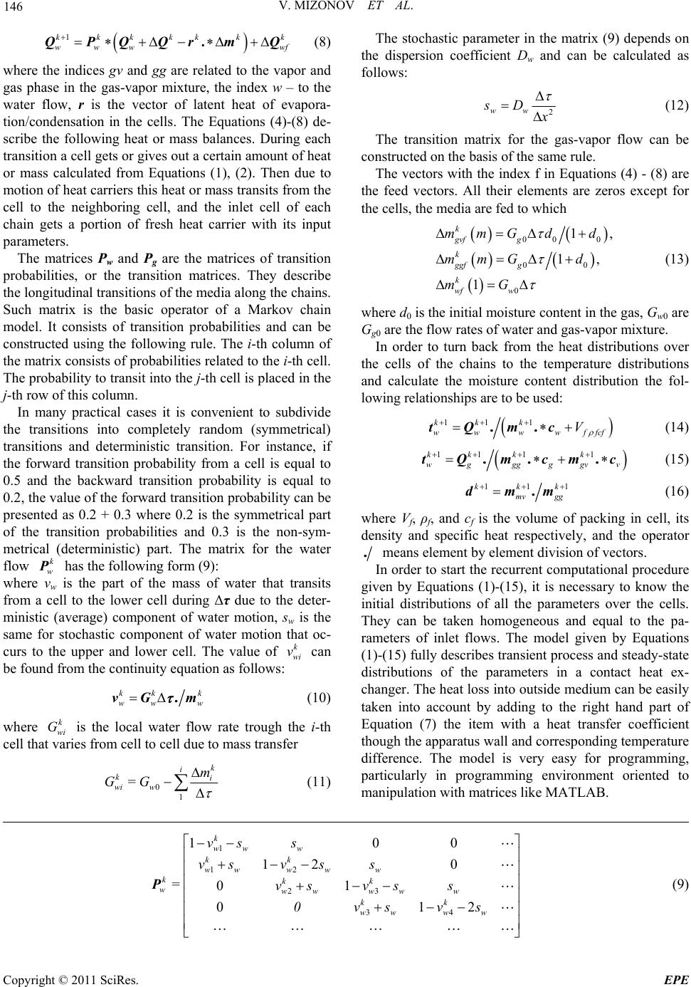 V. MIZONOV ET AL. Copyright © 2011 SciRes. EPE 146 k wf 1kkkkkk www .QPQQrmQ (8) The stochastic parameter in the matrix (9) depends on the dispersion coefficient Dw and can be calculated as follows: where the indices gv and gg are related to the vapor and gas phase in the gas-vapor mixture, the index w – to the water flow, r is the vector of latent heat of evapora- tion/condensation in the cells. The Equations (4)-(8) de- scribe the following heat or mass balances. During each transition a cell gets or gives out a certain amount of heat or mass calculated from Equations (1), (2). Then due to motion of heat carriers this heat or mass transits from the cell to the neighboring cell, and the inlet cell of each chain gets a portion of fresh heat carrier with its input parameters. 2 ww sD x (12) The transition matrix for the gas-vapor flow can be constructed on the basis of the same rule. The vectors with the index f in Equations (4) - (8) are the feed vectors. All their elements are zeros except for the cells, the media are fed to which 00 0 00 0 1, 1, 1 k gvf g k ggf g k wf w mmG dd mmGd mG (13) The matrices Pw and Pg are the matrices of transition probabilities, or the transition matrices. They describe the longitudinal transitions of the media along the chains. Such matrix is the basic operator of a Markov chain model. It consists of transition probabilities and can be constructed using the following rule. The i-th column of the matrix consists of probabilities related to the i-th cell. The probability to transit into the j-th cell is placed in the j-th row of this column. where d0 is the initial moisture content in the gas, Gw0 are Gg0 are the flow rates of water and gas-vapor mixture. In order to turn back from the heat distributions over the cells of the chains to the temperature distributions and calculate the moisture content distribution the fol- lowing relationships are to be used: In many practical cases it is convenient to subdivide the transitions into completely random (symmetrical) transitions and deterministic transition. For instance, if the forward transition probability from a cell is equal to 0.5 and the backward transition probability is equal to 0.2, the value of the forward transition probability can be presented as 0.2 + 0.3 where 0.2 is the symmetrical part of the transition probabilities and 0.3 is the non-sym- metrical (deterministic) part. The matrix for the water flow has the following form (9): k w P 11 1kk k ww wwffc V tQ mc.. f (14) 11 11kk kk wg ggggv tQ mcmc.. . v (15) 11kkk mv gg 1 dmm. (16) where Vf, ρf, and cf is the volume of packing in cell, its density and specific heat respectively, and the operator .means element by element division of vectors. In order to start the recurrent computational procedure given by Equations (1)-(15), it is necessary to know the initial distributions of all the parameters over the cells. They can be taken homogeneous and equal to the pa- rameters of inlet flows. The model given by Equations (1)-(15) fully describes transient process and steady-state distributions of the parameters in a contact heat ex- changer. The heat loss into outside medium can be easily taken into account by adding to the right hand part of Equation (7) the item with a heat transfer coefficient though the apparatus wall and corresponding temperature difference. The model is very easy for programming, particularly in programming environment oriented to manipulation with matrices like MATLAB. where vw is the part of the mass of water that transits from a cell to the lower cell during Δτ due to the deter- ministic (average) component of water motion, sw is the same for stochastic component of water motion that oc- curs to the upper and lower cell. The value of can be found from the continuity equation as follows: k wi v kk ww vG m .k w (10) where is the local water flow rate trough the i-th cell that varies from cell to cell due to mass transfer k wi G 0 1 k i ki wi w m G=G (11) 1 12 23 34 10 12 0 =01 01 k ww w kk www ww kkk wwwww w kk www w vs s vsvss vsvss 0vsvs 0 2 P (9) 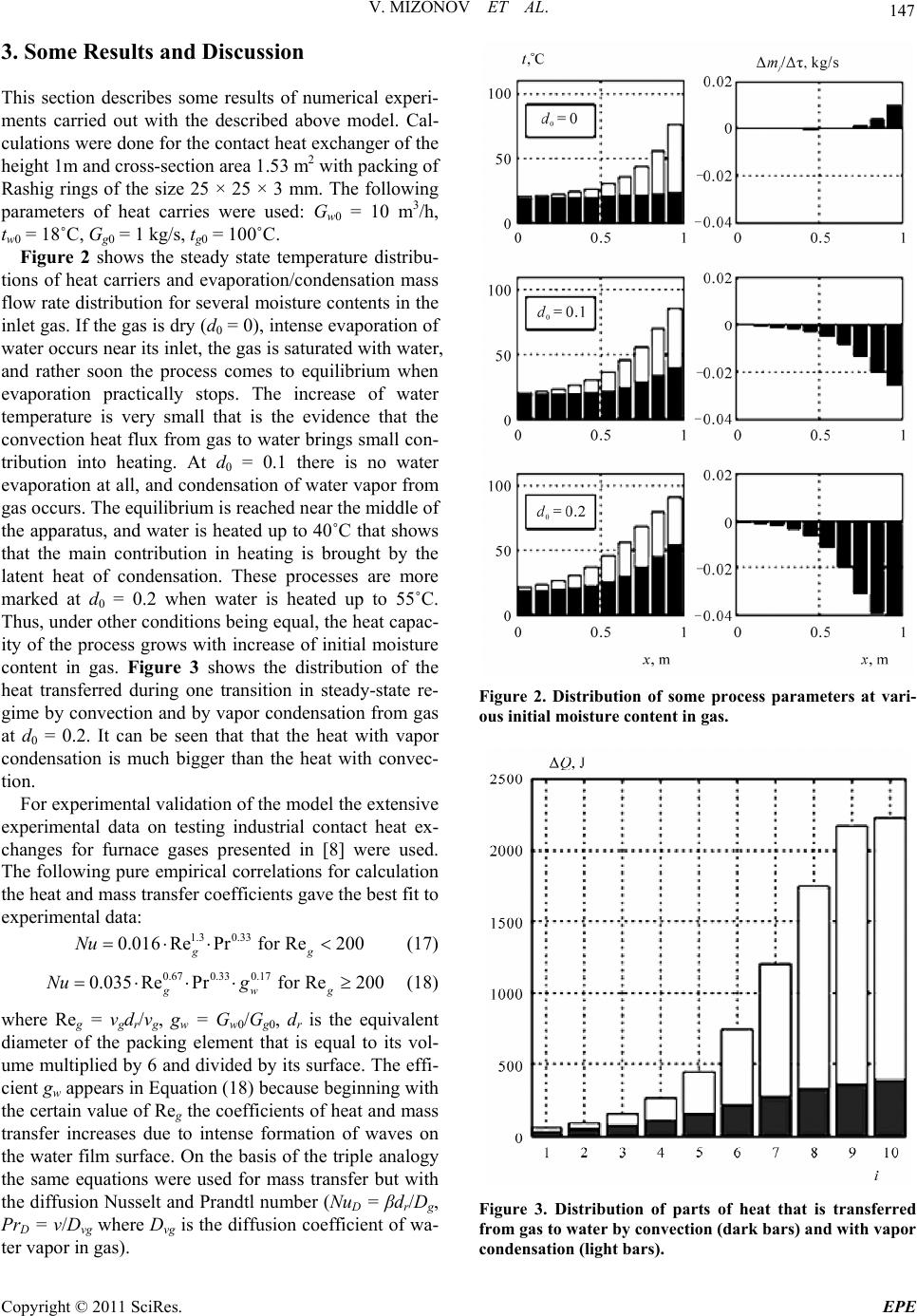 V. MIZONOV ET AL. Copyright © 2011 SciRes. EPE 147 3. Some Results and Discussion This section describes some results of numerical experi- ments carried out with the described above model. Cal- culations were done for the contact heat exchanger of the height 1m and cross-section area 1.53 m2 with packing of Rashig rings of the size 25 × 25 × 3 mm. The following parameters of heat carries were used: Gw0 = 10 m3/h, tw0 = 18˚C, Gg0 = 1 kg/s, tg0 = 100˚C. Figure 2 shows the steady state temperature distribu- tions of heat carriers and evaporation/condensation mass flow rate distribution for several moisture contents in the inlet gas. If the gas is dry (d0 = 0), intense evaporation of water occurs near its inlet, the gas is saturated with water, and rather soon the process comes to equilibrium when evaporation practically stops. The increase of water temperature is very small that is the evidence that the convection heat flux from gas to water brings small con- tribution into heating. At d0 = 0.1 there is no water evaporation at all, and condensation of water vapor from gas occurs. The equilibrium is reached near the middle of the apparatus, and water is heated up to 40˚C that shows that the main contribution in heating is brought by the latent heat of condensation. These processes are more marked at d0 = 0.2 when water is heated up to 55˚C. Thus, under other conditions being equal, the heat capac- ity of the process grows with increase of initial moisture content in gas. Figure 3 shows the distribution of the heat transferred during one transition in steady-state re- gime by convection and by vapor condensation from gas at d0 = 0.2. It can be seen that that the heat with vapor condensation is much bigger than the heat with convec- tion. For experimental validation of the model the extensive experimental data on testing industrial contact heat ex- changes for furnace gases presented in [8] were used. The following pure empirical correlations for calculation the heat and mass transfer coefficients gave the best fit to experimental data: 1.3 0.33 0.016RePrfor Re200 gg Nu (17) 0.670.330.17 0.035Re PrforRe 200 gwg Nu g (18) where Reg = vgdr/νg, gw = Gw0/Gg0, dr is the equivalent diameter of the packing element that is equal to its vol- ume multiplied by 6 and divided by its surface. The effi- cient gw appears in Equation (18) because beginning with the certain value of Reg the coefficients of heat and mass transfer increases due to intense formation of waves on the water film surface. On the basis of the triple analogy the same equations were used for mass transfer but with the diffusion Nusselt and Prandtl number (NuD = βdr/Dg, PrD = ν/Dvg where Dvg is the diffusion coefficient of wa- ter vapor in gas). Figure 2. Distribution of some process parameters at vari- ous initial moisture content in gas. Figure 3. Distribution of parts of heat that is transferred from gas to water by convec tion (dark bars) a nd w ith vapor condensation (light bars). 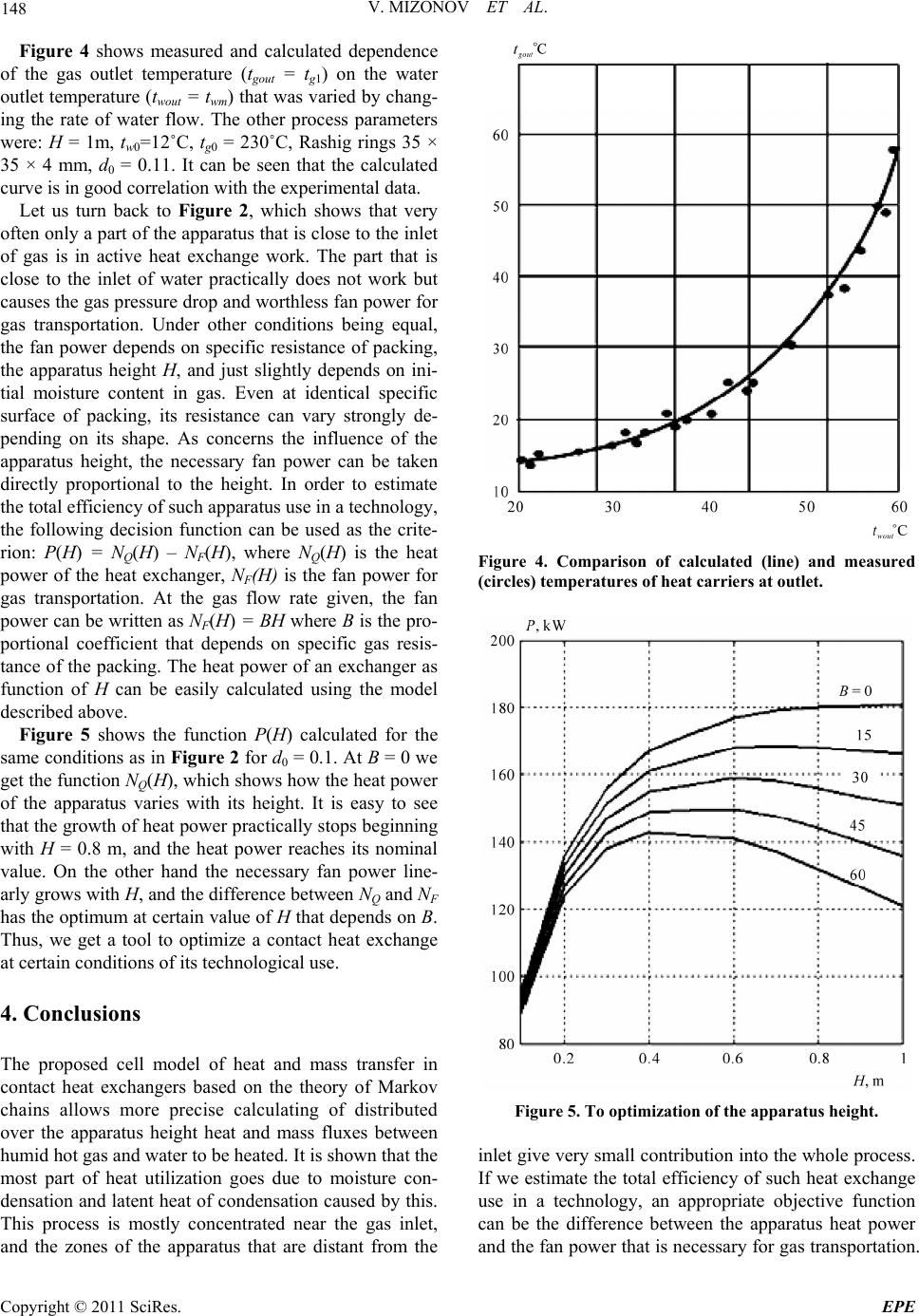 148 V. MIZONOV ET AL. Figure 4 shows measured and calculated dependence of the gas outlet temperature (tgout = tg1) on the water outlet temperature (twout = twm) that was varied by chang- ing the rate of water flow. The other process parameters were: H = 1m, tw0=12˚C, tg0 = 230˚C, Rashig rings 35 × 35 × 4 mm, d0 = 0.11. It can be seen that the calculated curve is in good correlation with the experimental data. Let us turn back to Figure 2, which shows that very often only a part of the apparatus that is close to the inlet of gas is in active heat exchange work. The part that is close to the inlet of water practically does not work but causes the gas pressure drop and worthless fan power for gas transportation. Under other conditions being equal, the fan power depends on specific resistance of packing, the apparatus height H, and just slightly depends on ini- tial moisture content in gas. Even at identical specific surface of packing, its resistance can vary strongly de- pending on its shape. As concerns the influence of the apparatus height, the necessary fan power can be taken directly proportional to the height. In order to estimate the total efficiency of such apparatus use in a technology, the following decision function can be used as the crite- rion: P(H) = NQ(H) – NF(H), where NQ(H) is the heat power of the heat exchanger, NF(H) is the fan power for gas transportation. At the gas flow rate given, the fan power can be written as NF(H) = BH where B is the pro- portional coefficient that depends on specific gas resis- tance of the packing. The heat power of an exchanger as function of H can be easily calculated using the model described above. Figure 5 shows the function P(H) calculated for the same conditions as in Figure 2 for d0 = 0.1. At B = 0 we get the function NQ(H), which shows how the heat power of the apparatus varies with its height. It is easy to see that the growth of heat power practically stops beginning with H = 0.8 m, and the heat power reaches its nominal value. On the other hand the necessary fan power line- arly grows with H, and the difference between NQ and NF has the optimum at certain value of H that depends on B. Thus, we get a tool to optimize a contact heat exchange at certain conditions of its technological use. 4. Conclusions The proposed cell model of heat and mass transfer in contact heat exchangers based on the theory of Markov chains allows more precise calculating of distributed over the apparatus height heat and mass fluxes between humid hot gas and water to be heated. It is shown that the most part of heat utilization goes due to moisture con- densation and latent heat of condensation caused by this. This process is mostly concentrated near the gas inlet, and the zones of the apparatus that are distant from the Figure 4. Comparison of calculated (line) and measured (circles) temperatures of heat carriers at outlet. Figure 5. To optimization of the apparatus height. inlet give very small contribution into the whole process. If we estimate the total efficiency of such heat exchange use in a technology, an appropriate objective function can be the difference between the apparatus heat power and the fan power that is necessary for gas transportation. Copyright © 2011 SciRes. EPE 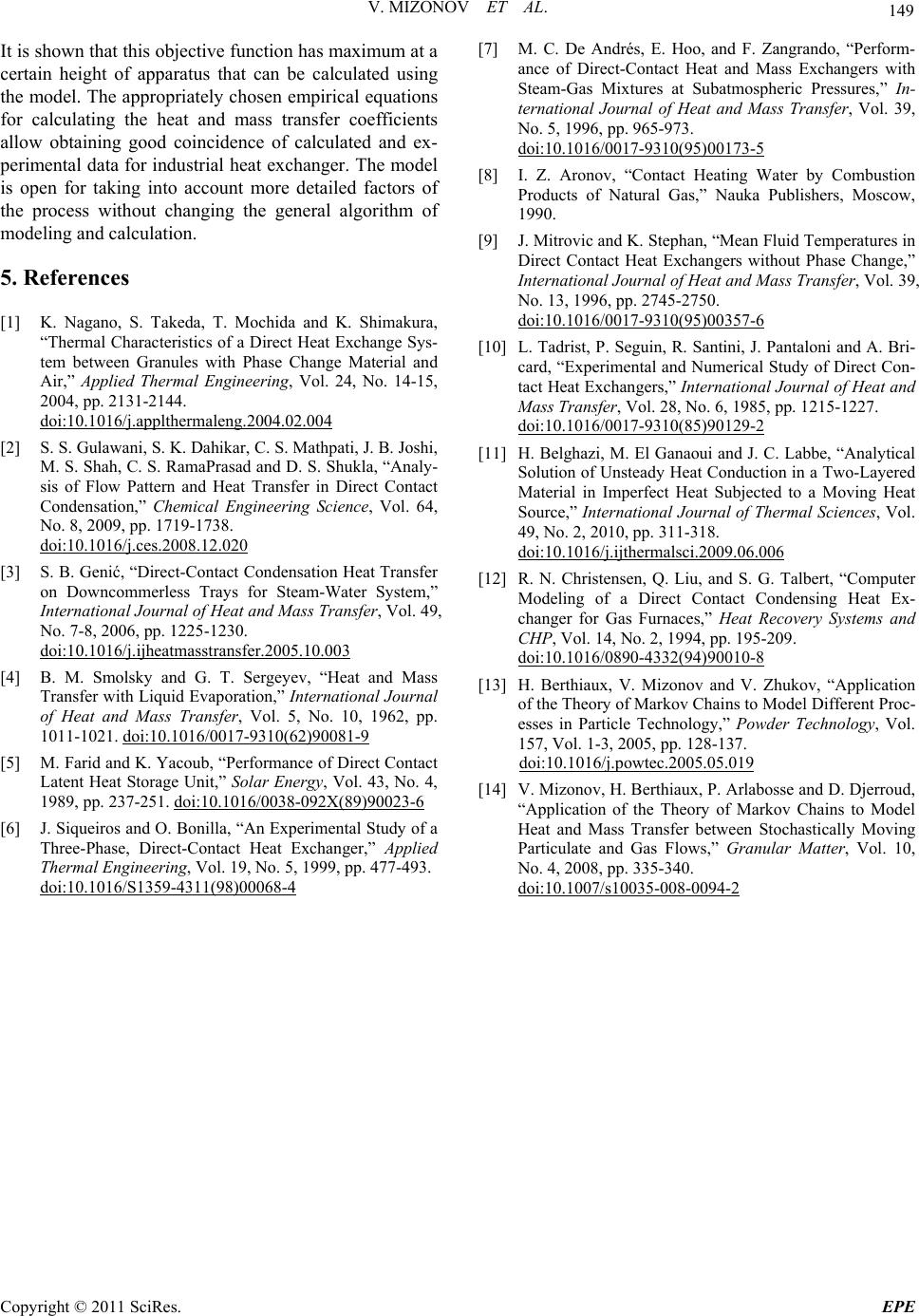 V. MIZONOV ET AL. Copyright © 2011 SciRes. EPE 149 [7] M. C. De Andrés, E. Hoo, and F. Zangrando, “Perform- ance of Direct-Contact Heat and Mass Exchangers with Steam-Gas Mixtures at Subatmospheric Pressures,” In- ternational Journal of Heat and Mass Transfer, Vol. 39, No. 5, 1996, pp. 965-973. doi:10.1016/0017-9310(95)00173-5 It is shown that this objective function has maximum at a certain height of apparatus that can be calculated using the model. The appropriately chosen empirical equations for calculating the heat and mass transfer coefficients allow obtaining good coincidence of calculated and ex- perimental data for industrial heat exchanger. The model is open for taking into account more detailed factors of the process without changing the general algorithm of modeling and calculation. [8] I. Z. Aronov, “Contact Heating Water by Combustion Products of Natural Gas,” Nauka Publishers, Moscow, 1990. [9] J. Mitrovic and K. Stephan, “Mean Fluid Temperatures in Direct Contact Heat Exchangers without Phase Change,” International Journal of Heat and Mass Transfer, Vol. 39, No. 13, 1996, pp. 2745-2750. doi:10.1016/0017-9310(95)00357-6 5. References [1] K. Nagano, S. Takeda, T. Mochida and K. Shimakura, “Thermal Characteristics of a Direct Heat Exchange Sys- tem between Granules with Phase Change Material and Air,” Applied Thermal Engineering, Vol. 24, No. 14-15, 2004, pp. 2131-2144. doi:10.1016/j.applthermaleng.2004.02.004 [10] L. Tadrist, P. Seguin, R. Santini, J. Pantaloni and A. Bri- card, “Experimental and Numerical Study of Direct Con- tact Heat Exchangers,” International Journal of Heat and Mass Transfer, Vol. 28, No. 6, 1985, pp. 1215-1227. doi:10.1016/0017-9310(85)90129-2 [2] S. S. Gulawani, S. K. Dahikar, C. S. Mathpati, J. B. Joshi, M. S. Shah, C. S. RamaPrasad and D. S. Shukla, “Analy- sis of Flow Pattern and Heat Transfer in Direct Contact Condensation,” Chemical Engineering Science, Vol. 64, No. 8, 2009, pp. 1719-1738. doi:10.1016/j.ces.2008.12.020 [11] H. Belghazi, M. El Ganaoui and J. C. Labbe, “Analytical Solution of Unsteady Heat Conduction in a Two-Layered Material in Imperfect Heat Subjected to a Moving Heat Source,” International Journal of Thermal Sciences, Vol. 49, No. 2, 2010, pp. 311-318. doi:10.1016/j.ijthermalsci.2009.06.006 [3] S. B. Genić, “Direct-Contact Condensation Heat Transfer on Downcommerless Trays for Steam-Water System,” International Journal of Heat and Mass Transfer, Vol. 49, No. 7-8, 2006, pp. 1225-1230. doi:10.1016/j.ijheatmasstransfer.2005.10.003 [12] R. N. Christensen, Q. Liu, and S. G. Talbert, “Computer Modeling of a Direct Contact Condensing Heat Ex- changer for Gas Furnaces,” Heat Recovery Systems and CHP, Vol. 14, No. 2, 1994, pp. 195-209. doi:10.1016/0890-4332(94)90010-8 [4] B. M. Smolsky and G. T. Sergeyev, “Heat and Mass Transfer with Liquid Evaporation,” International Journal of Heat and Mass Transfer, Vol. 5, No. 10, 1962, pp. 1011-1021. doi:10.1016/0017-9310(62)90081-9 [13] H. Berthiaux, V. Mizonov and V. Zhukov, “Application of the Theory of Markov Chains to Model Different Proc- esses in Particle Technology,” Powder Technology, Vol. 157, Vol. 1-3, 2005, pp. 128-137. doi:10.1016/j.powtec.2005.05.019 [5] M. Farid and K. Yacoub, “Performance of Direct Contact Latent Heat Storage Unit,” Solar Energy, Vol. 43, No. 4, 1989, pp. 237-251. doi:10.1016/0038-092X(89)90023-6 [14] V. Mizonov, H. Berthiaux, P. Arlabosse and D. Djerroud, “Application of the Theory of Markov Chains to Model Heat and Mass Transfer between Stochastically Moving Particulate and Gas Flows,” Granular Matter, Vol. 10, No. 4, 2008, pp. 335-340. doi:10.1007/s10035-008-0094-2 [6] J. Siqueiros and O. Bonilla, “An Experimental Study of a Three-Phase, Direct-Contact Heat Exchanger,” Applied Thermal Engineering, Vol. 19, No. 5, 1999, pp. 477-493. doi:10.1016/S1359-4311(98)00068-4 |