

Paper Menu >>
Journal Menu >>
 Energy and Power En gi neering, 2011, 3, 69-78 doi:10.4236/epe.2011.32010 Published Online May 2011 (http://www.SciRP.org/journal/epe) Copyright © 2011 SciRes. EPE A Repetitive-PI Current Controller for Boost Single Phase PFC Converters Turki Kahawish Hassan Electrical Engineering Department, University of AL-Mustansiriya, Baghdad, Iraq E-mail: [email protected] Received November 27, 2010; revised January 4, 2011; accepted January 26, 2011 Abstract In this paper, the Author presents the theory and application of repetitive proportional integral current con- troller for boost single phase ac-dc converter with power factor correction (PFC). A repetitive controller which is inserted in series with the proportional integral (PI) controller shows very low crossover distortion of input current, low total harmonic distortion and very low tracking error when is compared with the con- ventional proportional integral controller. Full analysis of proposed controller is given and Matlab/Simulink is used for simulation. The simulation results show the validity of the proposed control method. Keywords: Boost Converter, Unity Power Factor Correction, Repetitive Control 1. Introduction The developments in power factor correction technology in the past two decades have enabled the design and im- plementation of single phase ac-dc boost converters with close to unity power factor and much less input current distortion that generated by simple diode rectification circuits. Typical PFC schemes use two cascaded loops: the first loop aims to regulate the boost dc output voltage and provide the amplitude for the reference to the second controller, which controls sinusoidal current provided from grid. This current always contains some residual distortion, especially in the vicinity of zero crossing of the input voltage. The reasons of this zero crossing dis- tortion (also referred to as cross distortion) are discussed by authors in [1,2] but no any effective method is sug- gested to reduce or eliminate this phenomenon. Feed forward current control methods for boost single phase PFC converters are suggested for robust control against parameters variation and to reduce the total harmonic distortion [3,4] .These methods need additional circuits and the cost is increased . Receptive control theory [5-7] originating from inter- nal model principle provides a solution for eliminating periodic errors which occur in a dynamic system. A re- petitive controller can be viewed as a periodic waveform generator augmented within the control loop of a control system, which is closed loop regulated by a feed back controller so that the periodic errors can be eliminated. A number of repetitive control schemes have been devel- oped and applied to eliminate periodic distortions in PWM inverters [8,9]. In this paper, a repetitive controller is proposed and designed to eliminate the zero crossing distortion of in- put current of the converter and to obtain good tracking performance. The design of the repetitive controller is performed by analyzing the frequency domain, and Ny- quist plot play a central role throughout the design phase. The feasibility of the proposed design technique is shown by simulation. The simulation results of the pro- posed system show a highly improvement compared to the conventional PI controlled system. The reminder of this paper is organized as follows. Section 2 gives operation principle of boost single phase PFC converter and formulates the problem. In Section 3, the principle of repetitive control is reviewed and a re- petitive controller for PFC boost converter is proposed. In section 4, the repetitive controller is designed and several simulation results for proposed and conventional systems are presented. Section 5 concludes the paper. 2. Operation Principe and Problem Formulation Power circuit configuration of a boost single-phase power factor correction (PFC) converter and its control scheme are shown in Figure 1(a) and (b) respectively. 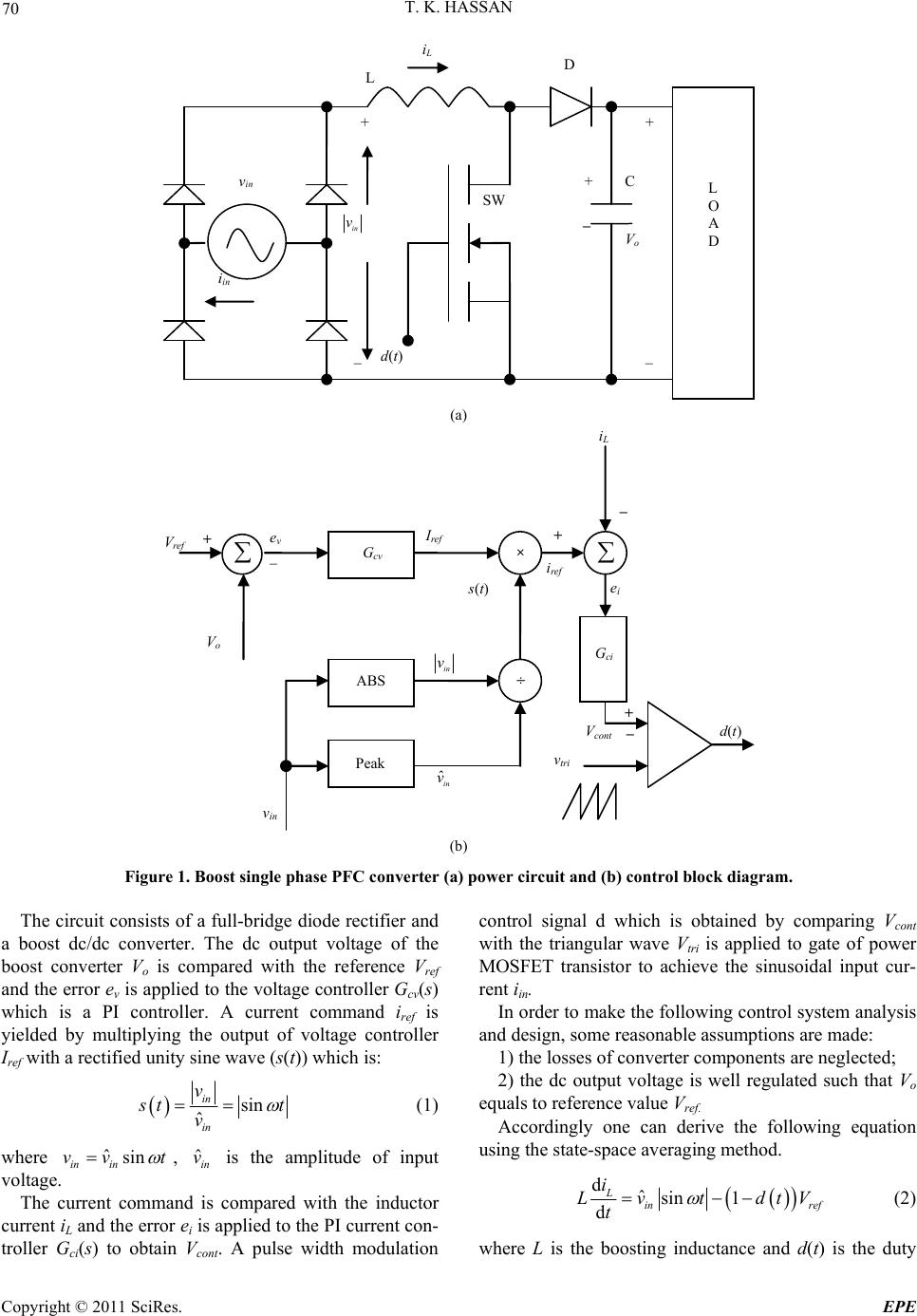 70 T. K. HASSAN V o in v _ L i in v in + _ _ + i L D C + d(t) SW L O A D (a) d(t) V o V ref + _ G cv e v ÷ × Peak ABS v in s(t) I ref i ref i L G ci + _ e i v tri + _ V cont in v ˆin v (b) Figure 1. Boost single phase PFC converter (a) power circuit and (b) control block diagram. The circuit consists of a full-bridge diode rectifier and a boost dc/dc converter. The dc output voltage of the boost converter Vo is compared with the reference Vref and the error ev is applied to the voltage controller Gcv(s) which is a PI controller. A current command iref is yielded by multiplying the output of voltage controller Iref with a rectified unity sine wave (s(t)) which is: sin ˆ in in v s t vt (1) where ˆsin in in vv t , is the amplitude of input voltage. ˆin v The current command is compared with the inductor current iL and the error ei is applied to the PI current con- troller Gci(s) to obtain Vcont. A pulse width modulation control signal d which is obtained by comparing Vcont with the triangular wave Vtri is applied to gate of power MOSFET transistor to achieve the sinusoidal input cur- rent iin. In order to make the following control system analysis and design, some reasonable assumptions are made: 1) the losses of converter components are neglected; 2) the dc output voltage is well regulated such that Vo equals to reference value Vref. Accordingly one can derive the following equation using the state-space averaging method. dˆsin 1 d L in ref i Lvt dtV t (2) where L is the boosting inductance and d(t) is the duty Copyright © 2011 SciRes. EPE  T. K. HASSAN 71 ratio function of the PWM modulator which can be ex- pressed as ˆ cont tri V dt V (3) where is the amplitude of the triangular wave. From (2) and (3), one can find ˆtri V ˆsin d ˆ d ref ref in L cont tri VV vt iV tLL LV (4) As shown in Figure 1(b), Vcont can be written in laplace form as contrefL ci Vs isisGs (5) The inductor current iL can be derived from (4) and (5) to be 21 11 ref in L V vs Gs isi s Gs sLG ssLG s r ef (6) where ˆ ref ci tri V GsG s sLV (7) and i ci p K Gs K s (8) where Kp and Ki are proportional and integral gains re- spectively. According to (6), the absolute value of input voltage can be viewed as a disturbance to the control loop. Also Vref can be considered as a constant disturbance. The objective of control is to make the inductor current tracks a sinusoidal reference current, in face of these distur- bances. In the conventional control method, a propor- tional integral (PI) controller Gci(s) is used in design and implementation, and also the most commonly used one in practical applications. However, it fails to yield excel- lent control performances in both tracking and distur- bance rejection issues. To solve these problems, a repeti- tive controller is proposed and applied to the current loop of boost converter. This controller is discussed in next section. 3. Repetitive Control 3.1. Principle of Repetitive Control Any periodic signal with period Ts can be generated by the free time delay system. The block diagram of time delay system including unity positive feedback is shown in Figure 2(a). The resulting transfer function is [5]: 1 S s sT R s T us e 9) where y(s) is the output and u(s) is the input. Due to this ys e Gs ( delay, the transfer function has infinitely many poles on the imaginary axis: jkωs (see Figure 2(b)).The poles can be found from 1.0 s sT sjks e for every k = 0, ±1, ±2,, where ωs = 2л/Ts. e model in (9) is said to be a he of the proposed repetitive control A controller including th repetitive controller and a system with such controller is called a repetitive control system. The basic concept of the repetitive controller origi- nates from the internal model principle [7]. This princi- ple state that the controlled output tracks a set of refer- ence inputs without steady state error if the model which generates these references is included in the stable closed loop system. For example, no steady state error occurs for step reference commands in type-1 stable feedback system that has an integrator (1/s) in the loop, i.e., the generator of step function .However ,stand-alone repeti- tive controller cannot yield good transient performance, therefore the repetitive controller is often used together with another controller such as P-I controller to give quick transient response. .2. PFC Boost Converter with Repetitive 3 Controller block diagramT system is shown in Figure 3. The repetitive controller CRP(s) is located in series with conventional PI controller Gci(s) of current loop of boost converter. The transfer function of the repetitive controller is: u(s) y(s) + + S sT e (a) Re I m 0 jω s 2 s j 2π s S T 2jω s (b) Figure 2. Generaf periodic signal. tor o Copyright © 2011 SciRes. EPE  T. K. HASSAN Copyright © 2011 SciRes. EPE 72 C RP (s) ref in V vs s S s T qse i p K K s ref V 1 s L 1 ˆtri V L is i ref (s) G ci (s) + + + + + + + _ Figure 3. Block diagram of a repetitive control system. 1 1S RP s T Cs qse (10) Note that CRP(s) is equivalent to the modified repeti- tiv ntrol system, (6) can be re e controller with a(s) = 1 as proposed by Hara et al. [5]. q(s) is a low pass filter that should be appropriately chosen so that good tracking performance is obtained without resultant system instability. The choice of q(s) is not straightforward and simulations are needed to choose the most appropriate filter [10]. For the proposed repetitive co written as: 2 11 1 ref in L RP RP RP ref RP V vs is s LGssLGs Gs is Gs (11) where ˆ ref RPci RP tri V Gs GsCs sLV (12) Let Us discuss the effectiveness of the repetitive con- troller according to (11) and (12). The transfer function CRP(s) is large enough for s = jkωs, k = 0, 1, 2, If the proportional integral controller Gci(s) of currentoop of boost converter is chosen such that l R Ps Gjk is suf- ficiently large for the selective range are multiples of frequency of reference current, then 1 of harmonics which R PsRPs Gjk Gjk . Since the denominator is jected and the inductor cur- rent tracks the sinusoidal reference current with very small steady state error. The stability condition t large, the disturbances are re hat is obtained in [5] is applied to ing proposition: ystem without repetitive controller, i.e., proposed repetitive control system to give the follow- In the repetitive control system shown in Figure 3 if the closed loop s 1s Gs, is stable and G 1qj Gj 0 where 2ˆ ref pi tri VKs K Gs sV L then the system is exponentially stable. The system without repetitive controller is stable since e control system is G(s) has no unstable poles. The repetitiv therefore exponentially stable if the Nyquist plot of G(s) [11] does not encircle the (–1, j0) point and lies outside of the circle of radius qj centered at the (–1, j0) point in the complex plane. The low pass filter q(s) should be chosen so that tuist plot of G(s) remains outside the circle for all frequencies. 4. Controller Design and Results he Nyq verter with power factor orrection has outer voltage loop and inner current loop. is shown in Figure 3. The pa for stable system th 4.1. Controller Design The boost single phase ac-dc con c Some nominal values and circuit parameters of the con- verter are shown in Table 1. Our investigation is focused on the inner current loop with repetitive controller that rameters of P-I controller of current loop are chosen as Kp = 0.8 and Ki = 300. The repetitive controller is in- serted in series with the PI controller. Figure 4 shows the Nyquist plot of G(s). The plot does not encircle the (–1, j0) point and e plot must be outside the circle of radius of qj . To ensure the stability for all frequencies the value of  T. K. HASSAN 73 qj Figure 4. Stability circle and Nyquist plot of G(s). Table 1. Simulated converter parameters. Input line voltage (peak) ˆin v= 170 V Input line frequency f = e F ncy V 50 Hz Smoothing capacitancC = 1000 µ Smoothing inductance L = 1 mH Rated power 500 W Carrier freque25 KHz Output voltage Vo = 300 qj between must be less than unity to prevent any contact obtain the cutoff frequency of the plot of G(s) and the circle (see the stability condition in the previous section). The gain of low pass filter q(s) is chosen as 0.98 to give stable system and good tracking performance. No systematic method to q(s), therefore simulation is required to find the best value from the point of view of good tracking and dis- turbances rejection. Accordingly, the cutoff frequency is chosen as 1000 HZ. It seems that 1000 HZ is reasonable choice since most periodic disturbances are expected to lie within this band. Let the filter q(s) be 0.98 1 2000π qs s (13) In our applications, we require a delay of Ts = 10 ms fo function r compensation of harmonics of fs = 100 Hz. Finally, we get a repetitive controller CRP(s ), which has transfer /100 0.98 1 RP s Cs e (14) 1 1 2000πs The effects that the designed repetiti CRP(s) has on the PFC boost converter system can be investigated by the bode plots of loop gains G(s) and G in, are clearly seen from the Bo ve controller RP(s) (without and with repetitive controller respec- tively) shown in Figure 5. The major characteristics of the repetitive controller, such as effective rejection of periodic disturbances and reduction of stability marg de plots. Note that the added repetitive controller in- creases the loop gain at particular frequencies, integral multiples of 100 Hz, maintaining a relatively unchanged gain at other frequencies. Let us considerer the sensitive- ity function 1 1RP Gs which is the transfer function from disturbance input to tracking error, which is of pri- mary importaning the performance of feedback ce in judg control systems. Gain increase at particular frequencies imulation is performed by Matlab/Simulink to verify leads to decrease in sensitivity at these frequencies. This implies that zero crossing distortion in inductor current which is considered as the periodic disturbances appear- ing at multiple of 100 Hz are more strongly attenuated by the repetitive controller than non periodic disturbances. 4.2. Results S Copyright © 2011 SciRes. EPE  74 T. K. HASSAN Figure 5. Bode plots of G(s) with (dash) and GRP(s) with solid. the proposed PFC boost con oller. The converter parameters in Table 1 and the de- co r current iL waveforms with 100 W (Rl = 900 Ω) w put voltage and input current for Rl = 450 Ω (output power equals 200 W) with repeti- t current is canceled compared with Figure 8( current when load re racking is achieved with repetitive controller (very sm verter with repetitive con-Figure 8(a) shows the in tr signed repetitive controller in the previous section are used in simulation. For all simulation results, the output voltage of the converter is constant and equals to 300 V. Figure 6(a) and (b) show the input current iin and the input voltage vin waveforms with and without repetitive ntroller respectively for 100 W output power and load resistance (Rl) of 900 Ω. The input current is in phase with input voltage and has an amplitude of 1.18 A with no zero switching distortion when repetitive controller is used. Figure 7(a) shows the reference current iref and the inducto hen the repetitive controller is applied. Comparison with waveforms in Figure 7(b) when only PI-controller is used indicates that current tracking performance is significantly improved by the proposed repetitive con- troller (reference and inductor current waveforms are coincident. tive controller. It is noticed that the zero crossing distor- tion in inpu b) when only P-I controller is used. Zero crossing distortion in input current shown in Fig- ure 6(b) is more than the distortion shown in Figure 8(b) because of increment in load current with load resistance of 450 Ω.More leading phase of input sistance is increased (less load current) which causes more zero crossing distortion [1]. This leading phase is not appeared when the proposed repetitive controller is used. Figure 9(a) and (b) show the reference and inductor current waveforms for load resistance of 450 Ω with and without repetitive controller respectively. It is clear that a good t all steady state error between reference and inductor currents). Figure 10(a) and (b) show the input voltage and input Copyright © 2011 SciRes. EPE  T. K. HASSAN 75 (a) (b) Figure 6. vin and iin waveforms for Rl = 900 Ω (a) With re- petitive controller; (b) Without repetitive controller. Hori- zontal axis 10 ms/div), vertical axes: voltage (50 V/div), current (2.5 A/div). (a) (a) (b) Figure 8. vin and iin waveforms for Rl = 450 Ω. (a) With re- petitive controller; (b) Without repetitive controller. Hori zontal axis (10 ms/div).Vertical axes: voltage (50 V/div), current (2.5 A/div). - (a) (b) Figure 7. iref and iL waveforms for Rl = 900 Ω. (a) With re- petitive controller; (b) Without repetitive controller. Hori- zontal axis (5 ms/div).Vertical axis (0.2 A/div). (b) Figure 9. iref and iL waveforms for Rl = 450 Ω. (a) With re- petitive controller; (b) Without repetitive controller. Hori zontal axis (5 ms/div). Vertical axis (0.5 A/div). - Copyright © 2011 SciRes. EPE  76 T. K. HASSAN (a) (b) Figure 10. vin and iin waveforms for Rl = 225 Ω. (a) With repetitive controller; (b) Without repetitive controller. Horizontal axis (10 ms/div). Vertical axes: voltage (5 V/div), current (2.5 A/div). Figure 11(a) shows the reference current and inductor ident. factor (PF) and the total harmonic distor- tio 900 Ω to 180 Ω. The input cur- re 0 current waveforms with and without repetitive controller respectively with Rl = 225 Ω (output power equals 400 W). current waveforms for Rl = 225 Ω when the repetitive controller is applied. It is noticed that the waveforms are coinc Figure 11(b) is similar to Figure 11(a) but no repeti- tive controller is used. No good tracking between the reference and inductor current is observed. The power n (THD) of input current with and without repetitive controller are calculated under various load and are listed in Table 2 and Table 3. As shown in Table 2, a highly reduction in total har- monic distortion of input current is shown when a repeti- tive controller is used compared with Table 3 (without repetitive controller). The waveforms of input voltage and input current for the proposed repetitive controlled PFC boost converter are plotted in Figure 12 when the load resistance Rl is suddenly changed from nt magnitude is increased from 1.18 A to 5.8 A. We can find that the input current iin always in phase with the input voltage vin even though under transient response. Consequently, the proposed repetitive controller (a) (b) Figure 11. (a) iref and iL waveforms for Rl = 225 Ω with repetitive controller. Horizontal axis (5ms/div).Vertical axis (0.5A/div); (b) iref and iL waveforms for Rl = 225 Ω withou repetitive controller. Horizl axis (5ms/div). Vertical All the previous results are obtained for input voltage ontroller. Rl (Ω) Output power (w) THD (%) PF t onta axis (0.5A/div). can keep good performance under the condition of load change. Table 2. Calculated THD and PF for various loads with repetitive c 1800 50 2.1 0.9992 900 100 0.9 0.9998 0.9999 450 200 0.41 225 400 0.22 1 Table 3. Calculated THD and PF arious loads with repetit controller. Rl (Ω) Output power (w) THD (%) PF for v ive 1800 50 34.16 0.9965 900 100 14.99 0.9977 0.9992 450 200 6.8 225 400 3.5 0.9998 Copyright © 2011 SciRes. EPE 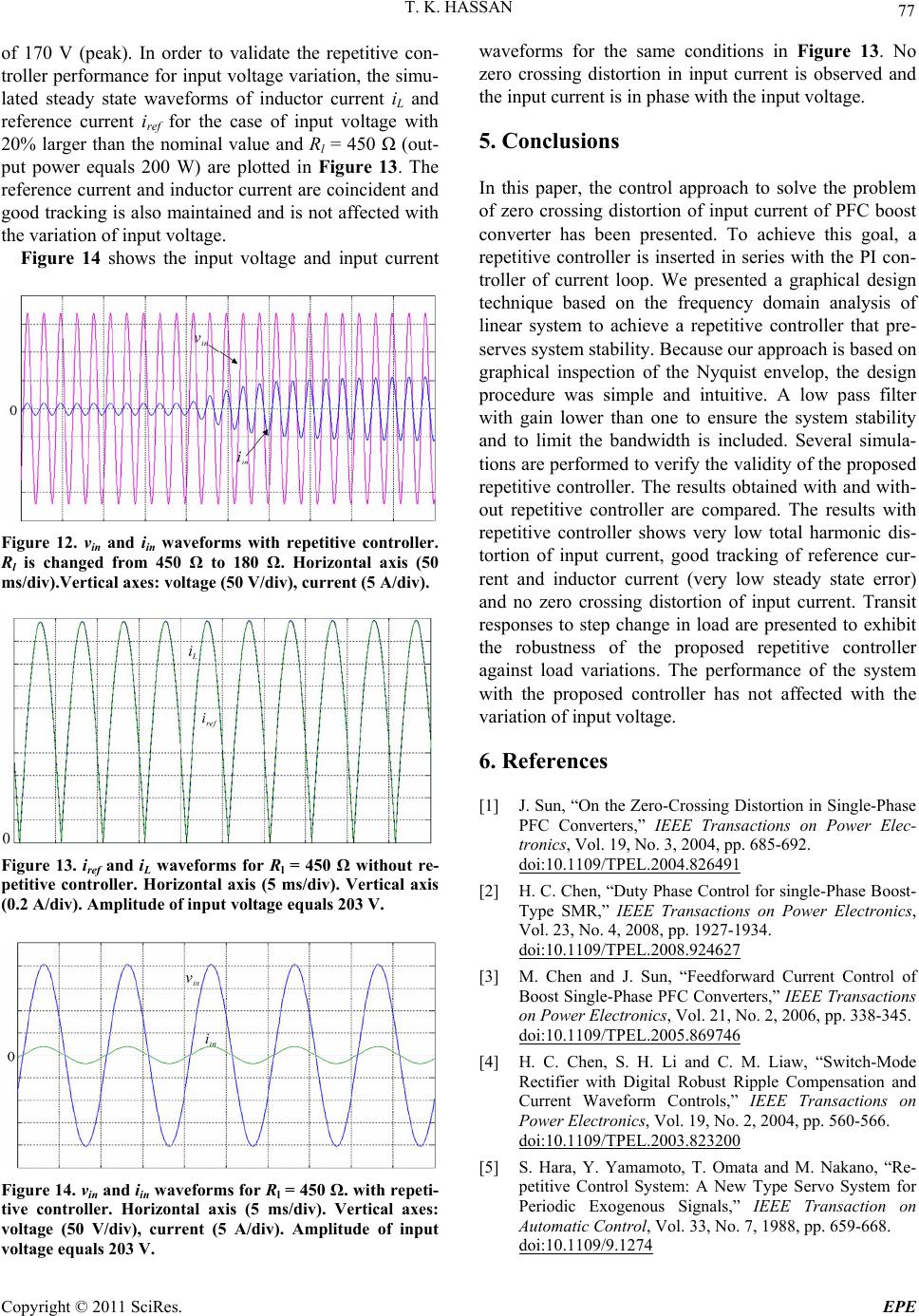 T. K. HASSAN 77 of 1(peak). der to valie repeon- troller performance foinput voltagariation, u- lated steady state eforms of inductor currLnd fee current or the case nput voith 70 V In ordate thtitive c r wav e vthe sim ent i a re renciref fof iltage w 20% larger than the nominal value and Rl = 450 Ω (out- put power equals 200 W) are plotted in Figure 13. The reference current and inductor current are coincident and good tracking is also maintained and is not affected with the variation of input voltage. Figure 14 shows the input voltage and input current Figure 12. vin and iin waveforms with repetitive controller. Rl is changed from 450 Ω to 180 Ω. Horizontal axis (50 ms/div).Vertical axes: voltage (50 V/div), current (5 A/div). Figure 13. iref and iL waveforms for Rl = 450 Ω without re- petitive controller. Horizontal axis (5 ms/div). Vertical axis (0.2 A/div). Amplitude of input voltage equals 203 V. Figure 14. vin and iin waveforms for Rl = 450 Ω. with repeti- tive controller. Horizontal axis (5 ms/div). Vertical ax voltage (50 V/div), current (5 A/div). Amplitude of input voltage equals 203 V. waveforms for the same conditions in Figure 13. No zero crossing distortion in input current is observed and the input current is in phase with the input voltage. 5. Conclusions In this paper, the control approach to solve the problem of zero crossing distortion of input current of PFC boost converter has been presented. To achieve this goal, a repetitive controller is inserted in series with the PI con y. Because our approach is based on bility ndwidth is included. Several simula- to verify the validity of the proposed es: - troller of current loop. We presented a graphical design technique based on the frequency domain analysis of linear system to achieve a repetitive controller that pre- serves system stabilit graphical inspection of the Nyquist envelop, the design procedure was simple and intuitive. A low pass filter with gain lower than one to ensure the system sta and to limit the ba tions are performed repetitive controller. The results obtained with and with- out repetitive controller are compared. The results with repetitive controller shows very low total harmonic dis- tortion of input current, good tracking of reference cur- rent and inductor current (very low steady state error) and no zero crossing distortion of input current. Transit responses to step change in load are presented to exhibit the robustness of the proposed repetitive controller against load variations. The performance of the system with the proposed controller has not affected with the variation of input voltage. 6. References [1] J. Sun, “On the Zero-Crossing Distortion in Single-Phase PFC Converters,” IEEE Transactions on Power Elec- tronics, Vol. 19, No. 3, 2004, pp. 685-692. doi:10.1109/TPEL.2004.826491 [2] H. C. Chen, “Duty Phase Control for single-Phase Boost- Type SMR,” IEEE Transactions on Power Electronics, Vol. 23, No. 4, 2008, pp. 1927-1934. doi:10.1109/TPEL.2008.924627 [3] M. Chen and J. Sun, “Feedforward Current Control of Boost Single-Phase PFC Converters,” IEEE Transactions on Power Electronics, Vol. 21, No. 2, 2006, pp. 338-345. doi:10.1109/TPEL.2005.869746 . H. Li and C. M. Liaw, “Switch-Mode Digital Robust Ripple Compensation and Current Waveform Controls,” IEEE Transactions on [4] H. C. Chen, S Rectifier with Power Electronics, Vol. 19, No. 2, 2004, pp. 560-566. doi:10.1109/TPEL.2003.823200 [5] S. Hara, Y. Yamamoto, T. Omata and M. Nak petitive Control System: A New ano, “Re- Type Servo System for Periodic Exogenous Signals,” IEEE Transaction on Automatic Control, Vol. 33, No. 7, 1988, pp. 659-668. doi:10.1109/9.1274 Copyright © 2011 SciRes. EPE  T. K. HASSAN Copyright © 2011 SciRes. EPE 78 ontrol System Design,” [9] G. Escobar, A. A. Valdez, J. L. Ramos and P. Mattavelli, “Repetitive-Based Controller for a UP [6] T. Inoue, “Practical Repetitive C IEEE Proceedings of 29th Conference on Decision and control, Honolulu, 5-7 December1990, pp. 1673-1678. doi: 10.1109/CDC.1990.203906 [7] B. A. France and W. M. Wonha S Inverter to Com- pensate Unbalance and Harmonic Distortion,” IEEE Transactions on Industrial Electronics, Vol. 54, No. 1, 2007, pp. 504-510. doi:10.1109/TIE.2006.888803 [10] J. H. Moon, M. N. Lee and M. J. Chung, “Repetitive Control for the Track-Following Serv m, “The Internal Model Principle for Linear Multivariable Regulators,” Applied Mathematics and Optimization, Vol. 2, No. 2, pp. 170- 194, 1975. doi: 10.1007/BF01447855 [8] Y. Y. Tzou, S. L. Jung, and H. C. Yeh, “Adaptive Repe tive Control of PWM Inverter o System of an Op- tical Disk Drive,” IEEE Transactions on Control Systems Technology, Vol. 6, No. 5, 1998, pp. 663-670. doi:10.1109/87.709501 [11] K. Ogata, “Modern Control Engineering,” 4th Edition, Prentice Hall, New Jersey, 2002. ti- s for Very Low THD Ac-Voltage Regulation with Unknown Loads,” IEEE Transactions on Power Electronics, Vol. 14, No. 5, 1999, pp. 973-981. doi:10.1109/63.788503 Nomenclature o Dc output voltage of boost converter. ref Reference voltage for voltage loop. v Voltage error (the difference between refer- ence and output voltage). cv(s) Voltage controller transfer function. voltage controller. e wave. t)). n current ction. Vcont Output of current controller. V Triangular wave. Amplitude of triangular wave. in Ac input current to the rectifier. L Boosting inductance. d(t) Duty ratio. Kp Proportional gain of current controller. ller. on. troller. out repetitive unction with repetitive . tri ˆin v i V V e G Iref Output of (t) Unity sin Ki Integral gain of current contro snsfer functis q() Low pass filter tra CRP siref Current command (Iref multiplied by s( () Transfer function of repetitive con vin Ac input voltage to the rectifier G(s) Open loop transfer function with ˆin vAmplitude of ac input voltage. iL Inductor current. controller). transfer f GRP(s) Open loop ei Current error (the difference betwee t). controller. /sec) ωs Double of input line frequency (radcommand and inductor curren s) Cu transfer funGci(rrent controller |