

Paper Menu >>
Journal Menu >>
 J. Electromagnetic Analysis & Applications, 2009, 2: 85-91 doi:10.4236/jemaa.2009.12013 Published Online June 2009 (www.SciRP.org/journal/jemaa) Copyright © 2009 SciRes JEMAA 1 Distance Measure Based Rules for Voltage Regulation with Loss Reduction Y. Rosales Hernandez, T. Hiyama Department of Computer Science and Electrical Engineering, Kumamoto University, Kumamoto, Japan. Email: [email protected].kumamoto-u.ac.jp, hiya[email protected] Received March 19th, 2009; revised May 25th, 2009; accepted May 28th, 2009. ABSTRACT This paper presents a rule-based technique to control the voltage in a power transmission network. Transformers with a tap changer installed in the system are selected by the proposed technique as control devices. For each bus under volt- age violation, the most effective control device is selected by using the minimum electric distance criteria. In order to demonstrate the efficiency of the method, several simulations were performed using an IEEE 30-bus network as a model system. The distance measure technique is compared with classic voltage regulation approach and a genetic algorithm based. The results obtained show the robustness of the proposed method. Keywords: Knowledge Based Systems, Losses, Voltage Control 1. Introduction Current approaches to the operation of a modern distribu- tion network demand high operational performance of the system and consequently require highly effective control strategies. Although voltage deviation control is one of the problems that has been extensively investigated, it still remains as an important topic to deal with. Voltage control algorithms may be classified into two categories: rule-based and network model-based. Rule-based algo- rithms use rules that control switched capacitors and transformer tap changers based on real-time measure- ments and past experience. Network model-based sys- tems use network topology, impedance, real-time meas- urements and statistical information to establish the cur- rent state of the system. It then applies optimization tech- niques to get the best possible solution. Within the net- work models-based systems there are many different ap- proaches. A simulated annealing technique for global optimal solution is presented in [1]. The authors propose a knowledge-based expert system which detects buses with maximum voltage deviations and operates the near- est available transformer control unit to correct the prob- lem. Then, a simulated annealing algorithm is utilized to solve the problem of capacitors manipulation. The paper shows a very good result in terms of power loss reduc- tions but does not guarantee an economical use of trans- formers operations. Restriction in the number of switch- ing operation is the focus in [2]. Here, dynamic pro- gramming and fuzzy logic algorithms are combined to control voltages and reduce power losses. The problem is decomposed into two sub-problems: first, the control of the load tap changers (LTC) and capacitor banks at sub- station level and second, the control of the capacitor banks installed at the feeder level. Dynamic program- ming is used in sub-problem 1 and fuzzy logic is adopted for the second sub-problem. Simulation results show the excellent performance of the proposed approach. The use of genetic algorithms is another approach to the control of voltage and reactive power in the system. The ap- proach in [3] combines the benefits of a linearized system model and genetic algorithms (GA). Whenever a voltage correction is demanded, an initial calculation of the sen- sitivity matrix is done in order to identify an initial popu- lation for the GA. Then the GA finds a proper set of con- trol actions to execute. The method offers good solutions to the voltage/reactive power problem and also reduces the number of control actions. Authors in [4] use a method based on an artificial neural network to find the suitable capacitor switching regime for every load state. The main objective is to reduce power losses and the only constraint considered is bus voltage. The advantage of this method is the short calculation time. However, in real applications, it might be difficult to use because the sys- tem requires training sessions every time any small change is made to the network topology. The approach presented in this paper is rule-based and is a new decision-making tool for centralized control of voltage. When the system lacks automatic function con- trol the task has to be performed manually by the super- 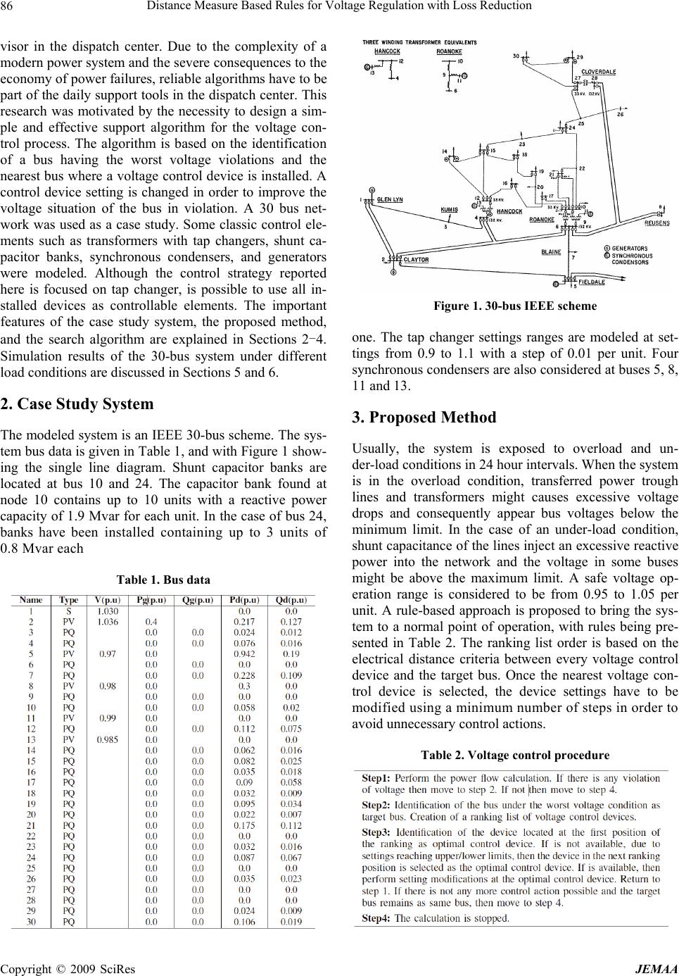 Distance Measure Based Rules for Voltage Regulation with Loss Reduction 86 visor in the dispatch center. Due to the complexity of a modern power system and the severe consequences to the economy of power failures, reliable algorithms have to be part of the daily support tools in the dispatch center. This research was motivated by the necessity to design a sim- ple and effective support algorithm for the voltage con- trol process. The algorithm is based on the identification of a bus having the worst voltage violations and the nearest bus where a voltage control device is installed. A control device setting is changed in order to improve the voltage situation of the bus in violation. A 30 bus net- work was used as a case study. Some classic control ele- ments such as transformers with tap changers, shunt ca- pacitor banks, synchronous condensers, and generators were modeled. Although the control strategy reported here is focused on tap changer, is possible to use all in- stalled devices as controllable elements. The important features of the case study system, the proposed method, and the search algorithm are explained in Sections 2-4. Simulation results of the 30-bus system under different load conditions are discussed in Sections 5 and 6. 2. Case Study System The modeled system is an IEEE 30-bus scheme. The sys- tem bus data is given in Table 1, and with Figure 1 show- ing the single line diagram. Shunt capacitor banks are located at bus 10 and 24. The capacitor bank found at node 10 contains up to 10 units with a reactive power capacity of 1.9 Mvar for each unit. In the case of bus 24, banks have been installed containing up to 3 units of 0.8 Mvar each Table 1. Bus data Figure 1. 30-bus IEEE scheme one. The tap changer settings ranges are modeled at set- tings from 0.9 to 1.1 with a step of 0.01 per unit. Four synchronous condensers are also considered at buses 5, 8, 11 and 13. 3. Proposed Method Usually, the system is exposed to overload and un- der-load conditions in 24 hour intervals. When the system is in the overload condition, transferred power trough lines and transformers might causes excessive voltage drops and consequently appear bus voltages below the minimum limit. In the case of an under-load condition, shunt capacitance of the lines inject an excessive reactive power into the network and the voltage in some buses might be above the maximum limit. A safe voltage op- eration range is considered to be from 0.95 to 1.05 per unit. A rule-based approach is proposed to bring the sys- tem to a normal point of operation, with rules being pre- sented in Table 2. The ranking list order is based on the electrical distance criteria between every voltage control device and the target bus. Once the nearest voltage con- trol device is selected, the device settings have to be modified using a minimum number of steps in order to avoid unnecessary control actions. Table 2. Voltage control procedure Copyright © 2009 SciRes JEMAA 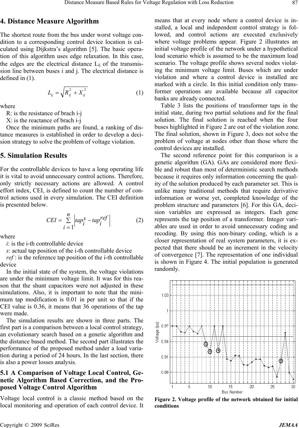 Distance Measure Based Rules for Voltage Regulation with Loss Reduction 87 4. Distance Measure Algorithm The shortest route from the bus under worst voltage con- dition to a corresponding control device location is cal- culated using Dijkstra’s algorithm [5]. The basic opera- tion of this algorithm uses edge relaxation. In this case, the edges are the electrical distance Lij of the transmis- sion line between buses i and j. The electrical distance is defined in (1). 22 ijij ij LRX (1) where R: is the resistance of brach i-j X: is the reactance of brach i-j Once the minimum paths are found, a ranking of dis- tance measures is established in order to develop a deci- sion strategy to solve the problem of voltage violation. 5. Simulation Results For the controllable devices to have a long operating life it is vital to avoid unnecessary control actions. Therefore, only strictly necessary actions are allowed. A control effort index, CEI, is defined to count the number of con- trol actions used in every simulation. The CEI definition is presented below. 1 nref s CEItap tap ii i (2) where i: is the i-th controllable device s: actual tap position of the i-th controllable device ref : is the reference tap position of the i-th controllable device In the initial state of the system, the voltage violations are under the minimum voltage limit. It was for this rea- son that the shunt capacitors were not adjusted in these simulations. Also, it is important to note that the mini- mum tap modification is 0.01 in per unit so that if the CEI value is 0.36, it means that 36 operations of the tap were made. The simulation results are shown in three parts. The first part is a comparison between a local control strategy, an evolutionary search based on a genetic algorithm and the distance based method. The second part illustrates the performance of the proposed method under a load varia- tion during a period of 24 hours. In the last section, there is also a power losses analysis. 5.1 A Comparison of Voltage Local Control, Ge- netic Algorithm Based Correction, and the Pro- posed Voltage Control Algorithm Voltage local control is a classic method based on the local monitoring and operation of each control device. It means that at every node where a control device is in- stalled, a local and independent control strategy is fol- lowed, and control actions are executed exclusively where voltage problems appear. Figure 2 illustrates an initial voltage profile of the network under a hypothetical load scenario which is assumed to be the maximum load scenario. The voltage profile shows several nodes violat- ing the minimum voltage limit. Buses which are under violation and where a control device is installed are marked with a circle. In this initial condition only trans- former operations are available because all capacitor banks are already connected. Table 3 lists the positions of transformer taps in the initial state, during two partial solutions and for the final solution. The final solution is reached when the four buses highlighted in Figure 2 are out of the violation zone. The final solution, shown in Figure 3, does not solve the problem of voltage at nodes other than those where the control devices are installed. The second reference point for this comparison is a genetic algorithm (GA). GAs are considered more flexi- ble and robust than most of deterministic search methods because it requires only information concerning the qual- ity of the solution produced by each parameter set. This is unlike many traditional methods that require derivative information or worse yet, completed knowledge of the problem structure and parameters [6]. For this GA, deci- sion variables are expressed as integers. Each gene represents the tap position of a transformer. Integer vari- ables are used in order to avoid unnecessary coding and recoding. By using this non-binary coding, which is a closer representation of real system parameters, it is ex- pected that there should be an increment in the velocity of convergence [7]. The representation of one individual is shown in Figure 4. The initial population is generated randomly. Figure 2. Voltage profile of the network obtained for initial conditions Copyright © 2009 SciRes JEMAA 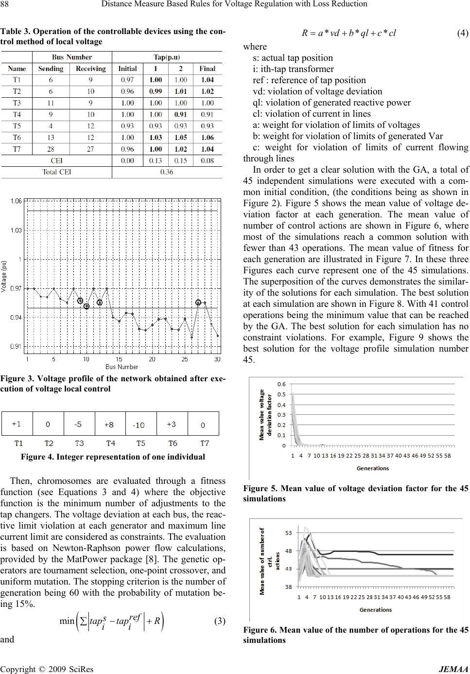 Distance Measure Based Rules for Voltage Regulation with Loss Reduction 88 Table 3. Operation of the controllable devices using the con- trol method of local voltage Figure 3. Voltage profile of the network obtained after exe- cution of voltage local control Figure 4. Integer representation of one individual Then, chromosomes are evaluated through a fitness function (see Equations 3 and 4) where the objective function is the minimum number of adjustments to the tap changers. The voltage deviation at each bus, the reac- tive limit violation at each generator and maximum line current limit are considered as constraints. The evaluation is based on Newton-Raphson power flow calculations, provided by the MatPower package [8]. The genetic op- erators are tournament selection, one-point crossover, and uniform mutation. The stopping criterion is the number of generation being 60 with the probability of mutation be- ing 15%. min ref s tap tapR ii (3) and ***Ra vdb qlccl (4) where s: actual tap position i: ith-tap transformer ref : reference of tap position vd: violation of voltage deviation ql: violation of generated reactive power cl: violation of current in lines a: weight for violation of limits of voltages b: weight for violation of limits of generated Var c: weight for violation of limits of current flowing through lines In order to get a clear solution with the GA, a total of 45 independent simulations were executed with a com- mon initial condition, (the conditions being as shown in Figure 2). Figure 5 shows the mean value of voltage de- viation factor at each generation. The mean value of number of control actions are shown in Figure 6, where most of the simulations reach a common solution with fewer than 43 operations. The mean value of fitness for each generation are illustrated in Figure 7. In these three Figures each curve represent one of the 45 simulations. The superposition of the curves demonstrates the similar- ity of the solutions for each simulation. The best solution at each simulation are shown in Figure 8. With 41 control operations being the minimum value that can be reached by the GA. The best solution for each simulation has no constraint violations. For example, Figure 9 shows the best solution for the voltage profile simulation number 45. Figure 5. Mean value of voltage deviation factor for the 45 simulations Figure 6. Mean value of the number of operations for the 45 simulations Copyright © 2009 SciRes JEMAA 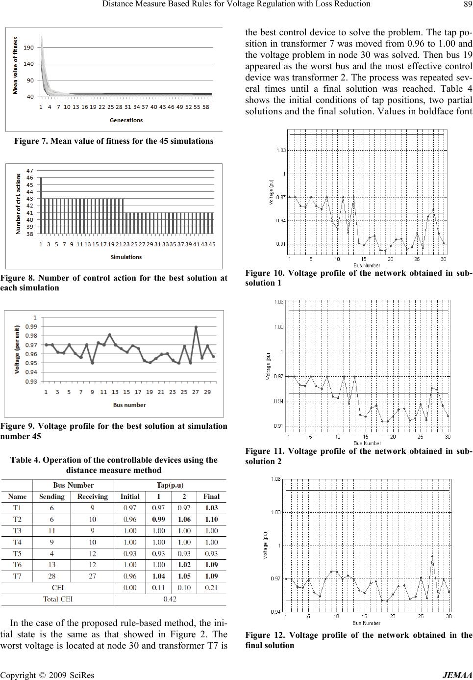 Distance Measure Based Rules for Voltage Regulation with Loss Reduction 89 Figure 7. Mean value of fitness for the 45 simulations Figure 8. Number of control action for the best solution at each simulation Figure 9. Voltage profile for the best solution at simulation number 45 Table 4. Operation of the controllable devices using the distance measure method In the case of the proposed rule-based method, the ini- tial state is the same as that showed in Figure 2. The worst voltage is located at node 30 and transformer T7 is the best control device to solve the problem. The tap po- sition in transformer 7 was moved from 0.96 to 1.00 and the voltage problem in node 30 was solved. Then bus 19 appeared as the worst bus and the most effective control device was transformer 2. The process was repeated sev- eral times until a final solution was reached. Table 4 shows the initial conditions of tap positions, two partial solutions and the final solution. Values in boldface font Figure 10. Voltage profile of the network obtained in sub- solution 1 Figure 11. Voltage profile of the network obtained in sub- solution 2 Figure 12. Voltage profile of the network obtained in the final solution Copyright © 2009 SciRes JEMAA 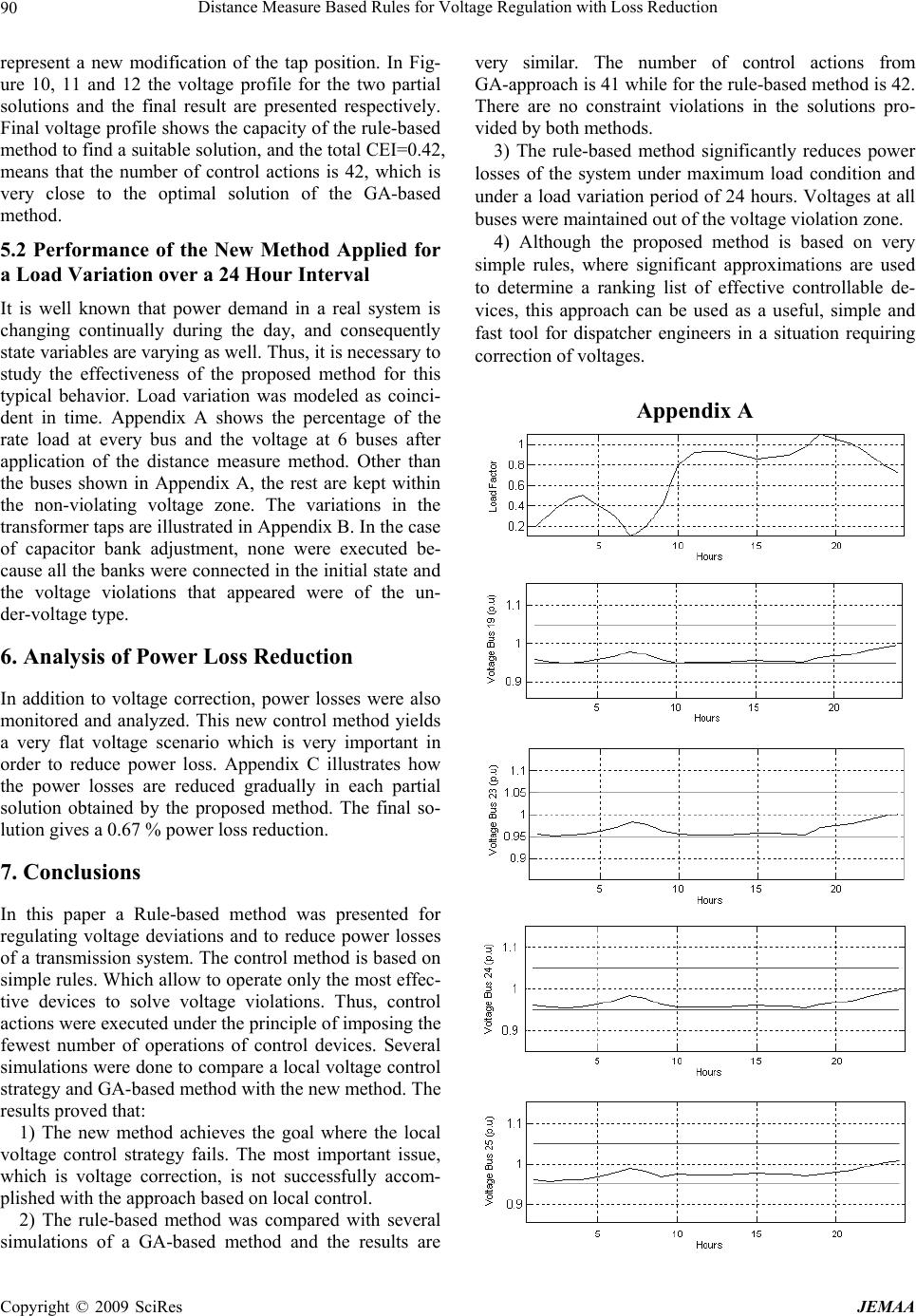 Distance Measure Based Rules for Voltage Regulation with Loss Reduction 90 represent a new modification of the tap position. In Fig- ure 10, 11 and 12 the voltage profile for the two partial solutions and the final result are presented respectively. Final voltage profile shows the capacity of the rule-based method to find a suitable solution, and the total CEI=0.42, means that the number of control actions is 42, which is very close to the optimal solution of the GA-based method. 5.2 Performance of the New Method Applied for a Load Variation over a 24 Hour Interval It is well known that power demand in a real system is changing continually during the day, and consequently state variables are varying as well. Thus, it is necessary to study the effectiveness of the proposed method for this typical behavior. Load variation was modeled as coinci- dent in time. Appendix A shows the percentage of the rate load at every bus and the voltage at 6 buses after application of the distance measure method. Other than the buses shown in Appendix A, the rest are kept within the non-violating voltage zone. The variations in the transformer taps are illustrated in Appendix B. In the case of capacitor bank adjustment, none were executed be- cause all the banks were connected in the initial state and the voltage violations that appeared were of the un- der-voltage type. 6. Analysis of Power Loss Reduction In addition to voltage correction, power losses were also monitored and analyzed. This new control method yields a very flat voltage scenario which is very important in order to reduce power loss. Appendix C illustrates how the power losses are reduced gradually in each partial solution obtained by the proposed method. The final so- lution gives a 0.67 % power loss reduction. 7. Conclusions In this paper a Rule-based method was presented for regulating voltage deviations and to reduce power losses of a transmission system. The control method is based on simple rules. Which allow to operate only the most effec- tive devices to solve voltage violations. Thus, control actions were executed under the principle of imposing the fewest number of operations of control devices. Several simulations were done to compare a local voltage control strategy and GA-based method with the new method. The results proved that: 1) The new method achieves the goal where the local voltage control strategy fails. The most important issue, which is voltage correction, is not successfully accom- plished with the approach based on local control. 2) The rule-based method was compared with several simulations of a GA-based method and the results are very similar. The number of control actions from GA-approach is 41 while for the rule-based method is 42. There are no constraint violations in the solutions pro- vided by both methods. 3) The rule-based method significantly reduces power losses of the system under maximum load condition and under a load variation period of 24 hours. Voltages at all buses were maintained out of the voltage violation zone. 4) Although the proposed method is based on very simple rules, where significant approximations are used to determine a ranking list of effective controllable de- vices, this approach can be used as a useful, simple and fast tool for dispatcher engineers in a situation requiring correction of voltages. Appendix A Copyright © 2009 SciRes JEMAA 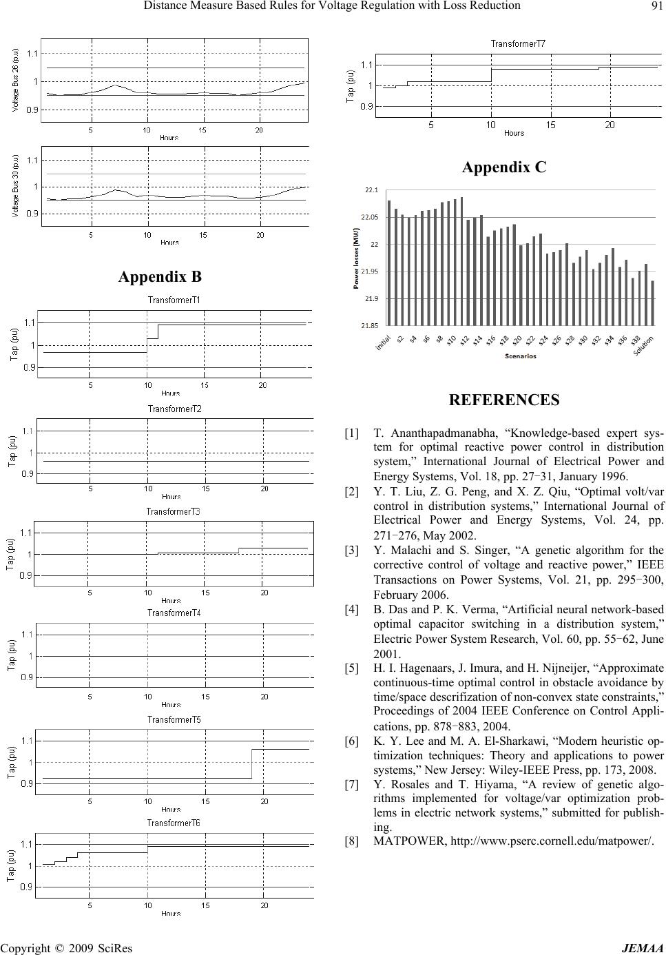 Distance Measure Based Rules for Voltage Regulation with Loss Reduction Copyright © 2009 SciRes JEMAA 91 Appendix C Appendix B REFERENCES [1] T. Ananthapadmanabha, “Knowledge-based expert sys- tem for optimal reactive power control in distribution system,” International Journal of Electrical Power and Energy Systems, Vol. 18, pp. 27-31, January 1996. [2] Y. T. Liu, Z. G. Peng, and X. Z. Qiu, “Optimal volt/var control in distribution systems,” International Journal of Electrical Power and Energy Systems, Vol. 24, pp. 271-276, May 2002. [3] Y. Malachi and S. Singer, “A genetic algorithm for the corrective control of voltage and reactive power,” IEEE Transactions on Power Systems, Vol. 21, pp. 295-300, February 2006. [4] B. Das and P. K. Verma, “Artificial neural network-based optimal capacitor switching in a distribution system,” Electric Power System Research, Vol. 60, pp. 55-62, June 2001. [5] H. I. Hagenaars, J. Imura, and H. Nijneijer, “Approximate continuous-time optimal control in obstacle avoidance by time/space descrifization of non-convex state constraints,” Proceedings of 2004 IEEE Conference on Control Appli- cations, pp. 878-883, 2004. [6] K. Y. Lee and M. A. El-Sharkawi, “Modern heuristic op- timization techniques: Theory and applications to power systems,” New Jersey: Wiley-IEEE Press, pp. 173, 2008. [7] Y. Rosales and T. Hiyama, “A review of genetic algo- rithms implemented for voltage/var optimization prob- lems in electric network systems,” submitted for publish- ing. [8] MATPOWER, http://www.pserc.cornell.edu/matpower/. |