

Paper Menu >>
Journal Menu >>
 Vol.3, No.4, 328-333 (2011) Natural Science http://dx.doi.org/10.4236/ns.2011.34043 Copyright © 2011 SciRes. OPEN ACCESS Effect of negative permittivity and permeability on the transmission of electromagnetic waves through a structure containing left-handed material Muin F. Ubeid1*, Mohammed M. Shabat1, Mohammed O. Sid-Ahmed2 1Department of Physics, Faculty of Science, Islamic University of Gaza, Gaza, Palestine; *Corresponding Author: [email protected] 2Department of Physics, Faculty of Science, Sudan University of Science and Technology, Khartoum, The Republic of The Sudan Received 5 March 2011; revised 23 March 2011; accepted 27 March 2011. ABSTRACT We investigate the characteristics of electro- magnetic wave reflection and transmission by multilayered structures consisting of a pair of left-handed material (LHM) and dielectric slabs inserted between two semi-infinite dielectric media. The theoretical aspect is based on Maxwell's equations and matching the boundary conditions for the electric and magnetic fields of the incident waves at each layer interface. We calculate the reflected and transmitted powers of the multilayered structure taking into account the widths of the slabs and the frequency de- pendence of permittivity and permeability of the LHM. The obtained results satisfy the law of conservation of energy. We show that if the semi-infinite dielectric media have the same refractive index and the slabs have the same width, then the reflected (and transmitted) pow- ers can be minimized (and maximized) and the powers-frequency curves show no ripple. On the other hand if the semi-infinite dielectric me- dia have different values of refractive indices and the slabs have different widths, then under certain conditions the situation of minimum and maximum values of the mentioned powers will be reversed. Keywords: Electromagnetic Waves; Left-Handed Materials; Frequency; Reflected and Transmitted Powers 1. INTRODUCTION Metamaterials (sometimes termed left-handed materi- als (LHMs)) are materials whose permittivity and permeability are both negative and consequently have negative index of refraction. These materials are artificial and theoretically discussed first by Veselago [1] over 40 years ago. The first realization of such materials, consisting of split-ring resenators (SRRs) and continuous wires, was first introduced by Pendry [2,3]. Regular ma- terials are materials whose and are both positive and termed right handed materials (RHMs). R. A. Shelby et al. [4] have studied negative refraction in LHMs. I. V. Shadrivov [5] has investigated nonlinear guided waves in LHMs. N. Garcia et al. [6] have shown that LHMs don’t make a perfect lens. Kong [7] has provided a gen- eral formulation for the electromagnetic wave interaction with stratified metamaterial structures. M. M. Shabat et al [8] have discussed Nonlinear TE surface waves in a left-handed material and magnetic super lattice wave- guide structure. I. Kourakis et al. [9] have investigated a nonlinear propagation of electromagnetic waves in nega- tive–refraction index LHM. H. Cory et al. [10] and C. Sabah et al. [11] have estimated high reflection coatings of multilayered structure. Oraizi et al. [12] have obtained a zero reflection from multilayered metamaterial struc- tures. In this paper we consider a structure consisting of LHM and dielectric slabs inserted between two semi- infinite dielectric media. A plane polarized wave is obliquely incident on it. We use Maxwell’s equations and match the boundary conditions for the electric and magnetic fields of the incident waves at each layer in- terface. Then we solve the obtained equations for the unknown parameters to calculate the reflection and transmission coefficients. We take into account the fre- quency dependence of permittivity and permeability of the LHM (in contradict with [10,11]), widths of the slabs, refractive indices of the media and angle of incidence of the incident waves. Maximum and minimum transmitted (minimum and maximum reflected) powers of the con- sidered structure are proposed. The numerical results are 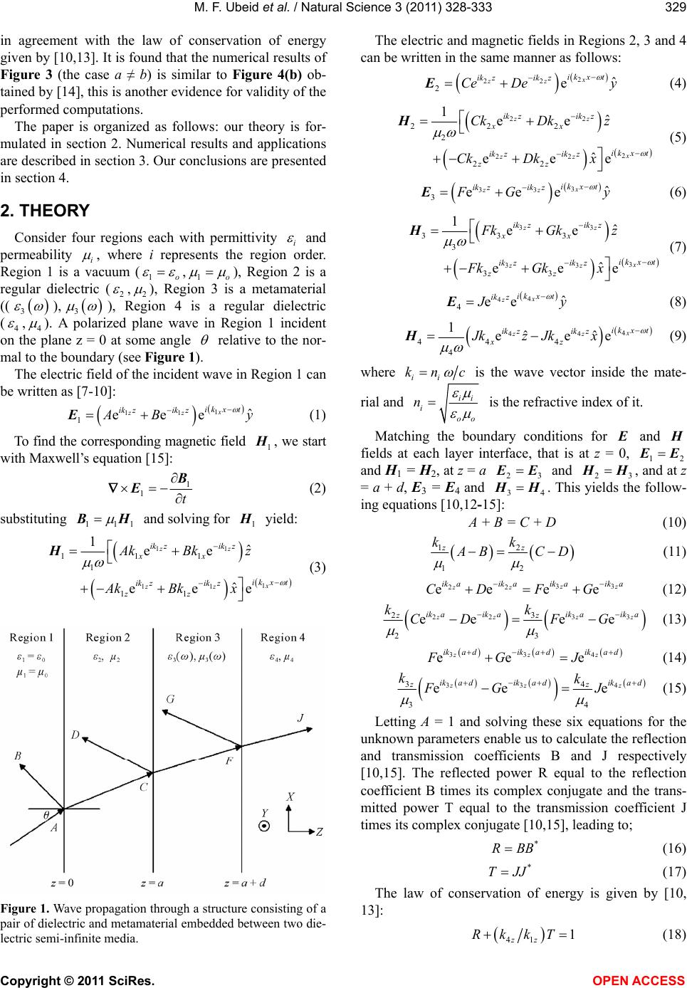 M. F. Ubeid et al. / Natural Science 3 (2011) 328-333 Copyright © 2011 SciRes. OPEN ACCESS 329 in agreement with the law of conservation of energy given by [10,13]. It is found that the numerical results of Figure 3 (the case a ≠ b) is similar to Figure 4(b) ob- tained by [14], this is another evidence for validity of the performed computations. The paper is organized as follows: our theory is for- mulated in section 2. Numerical results and applications are described in section 3. Our conclusions are presented in section 4. 2. THEORY Consider four regions each with permittivity i and permeability i , where i represents the region order. Region 1 is a vacuum (1o ,1o ), Region 2 is a regular dielectric (2 ,2 ), Region 3 is a metamaterial (( 3 ), 3 ), Region 4 is a regular dielectric (4 ,4 ). A polarized plane wave in Region 1 incident on the plane z = 0 at some angle relative to the nor- mal to the boundary (see Figure 1). The electric field of the incident wave in Region 1 can be written as [7-10]: 1 11 1ˆ eee x zz ik xt ik zik z A By E (1) To find the corresponding magnetic field 1 H , we start with Maxwell’s equation [15]: 1 1t B E (2) substituting 111 B H and solving for 1 H yield: 11 1 11 111 1 11 1ˆ ee ˆ eee zz x zz ik zikz xx ik xt ik zik z zz Ak Bk z Ak Bkx H (3) Figure 1. Wave propagation through a structure consisting of a pair of dielectric and metamaterial embedded between two die- lectric semi-infinite media. The electric and magnetic fields in Regions 2, 3 and 4 can be written in the same manner as follows: 2 22 2ˆ ex zz ik xt ik zik z Ce Dey E (4) 22 2 22 222 2 22 1ˆ ee ˆ eee zz x zz ik zik z xx ik xt ik zikz zz Ck Dk z Ck Dkx H (5) 3 33 3ˆ eee x zz ik xt ik zik z F Gy E (6) 33 3 33 333 3 33 1ˆ ee ˆ eee zz x zz ik zik z xx ik xt ik zik z zz Fk Gkz Fk Gkx H (7) 4 4 4ˆ ee x zik xt ik z J y E (8) 4 44 44 4 4 1ˆ ˆ eee x zz ik xt ik zik z xz Jkz Jkx H (9) where ii kn c is the wave vector inside the mate- rial and ii i oo n is the refractive index of it. Matching the boundary conditions for E and H fields at each layer interface, that is at z = 0, 12 E E and H1 = H2, at z = a 23 E E and 23 H H, and at z = a + d, E3 = E4 and 34 H H. This yields the follow- ing equations [10,12-15]: A + B = C + D (10) 12 12 zz kk A BCD (11) 33 22 ee ee z z zz ik aik a ik aik a CD FG (12) 33 22 3 2 23 ee ee zz zz ik aik a ik aik az zk kCDFG (13) 334 ee e zzz ikadikadika d FG J (14) 33 4 34 34 ee e zz z ikadikadika d zz kk FG J (15) Letting A = 1 and solving these six equations for the unknown parameters enable us to calculate the reflection and transmission coefficients B and J respectively [10,15]. The reflected power R equal to the reflection coefficient B times its complex conjugate and the trans- mitted power T equal to the transmission coefficient J times its complex conjugate [10,15], leading to; * RBB (16) * TJJ (17) The law of conservation of energy is given by [10, 13]: 41 1 zz RkkT (18)  M. F. Ubeid et al. / Natural Science 3 (2011) 328-333 Copyright © 2011 SciRes. OPEN ACCESS 330 where: 222 1sin iz i knn c (19) 3. NUMERICAL RESULTS AND APPLICATIONS For the metamaterial in region 3 we will employ a non-dispersive metamaterial with and given by [2,3,12,15-17]: 2 322 1eep eo e F i (20) 2 322 1mmp mo m F i (21) where ep and mp are the electric and magnetic plasma frequencies, eo and mo are the electric and magnetic resonance frequencies. e F and m F are the scaling filling parameters. We have used the following parameters in [15]: 2π10.95 GHz mp , 2π10.1 GHz mo , 0.26 m F , 2π13.3 GHz ep ,2π10.3 GHz eo , 0.37 e F, with no loss case i.e. 0 em . In this case, the frequency range in which 3 and 3 are negative ex- tends from 10.3 up to 11.4 GHz. The obtained values of 3 , 3 in addition to iz k are used in (10-15). These equations are solved for the parameters B and J. Then the reflected and transmitted powers R and T can be calculated. The transmitted power is plotted as a function of under different conditions as follows: The dependence of 3 on for the metamaterial in Region 3 is taken into account [2-5,15-17], it is con- sidered by [10, 11] to be 3o . The difference be- tween the two cases can be noticed from Figure 2. The thickness of the slabs is taken to be the same a = d, 23 nn, 14 nn, is kept constant. In this case the structure’s reflected and transmitted powers variation with frequency are smooth and show no ripples as shown in Figure 3. To check the validity of computations for the case a ≠ b as an example, let ω = 2π11 GHz, then: μ3 = –0.641 635 071, ε3 = –3.389 624 4113, k4z/k1z = 1, B = –0.570 959 7786 + 2.958 090 86i, J = –0.743 521 1938 + 0.184 524 7865i, R = 0.413 126 8376, T = 0.586 873 1625. In this case the left hand side of (18) is equal to 0.999 999 99 which verifies the law of conservation of energy. It can be realized from Figure 3 that this law is satisfied by the performed computations. The same procedure can be applied to other computations in this paper. Low reflected and high transmitted powers can be achieved if 14 nn, 23 nn and a = d [10]. In this case R = 0 (minimum) and T = 1 (maximum) for any frequency and for any angle of incidence (Figure 4). If Figure 2. Transmitted power variation with frequency. Two cases are taken into account: μ3 is a function of ω, μ3 is a con- stant (–μ0). 14 nn (and a = d, 23 nn), then both R and T de- pend on the values of the refractive indices of the initial and final media 1 n and 4 n, and on the angle of inci- dence see Figures 5 and 6. High reflected and Low transmitted powers: in order to maximize R and minimize T, one has to choose a pair of adjacent dielectric and metamaterial slabs with highly contrasted refractive indices (12 nn,23 nn, 34 nn ) and 23πo na ndc [10], where o is the central frequency (o = 10.9 GHz). In this case by a judicious combination of metamaterial and dielectric slabs, a high-reflected and low-transmitted powers are achieved, for which the dependence of R and T on frequency and on the angle of incidence is consequently diminished (Figure 7). Note that the maximum value of T is 0.09 at 0o. This value is smaller by a factor of 11 than that ob- tained in Figure 4. Figure 7 is different from that ob- tained by [10,11] in the fact that, they had used a LHM with properties invariant with frequency. In our paper, the properties of the LHM in Region 3 depends on fre- quency (this can be realized from Eqs.20 and 21). 4. CONCLUSIONS The propagation of electromagnetic waves through multilayered structures consisting of a pair of LHM and dielectric slabs inserted between semi-infinite dielectric media has been studied. The followed method has been based on Maxwell's equations and matching the bound- ary conditions for the electric and magnetic fields at each interface layer. The frequency dependence of and of the LHM has been taken into account. The reflected and transmitted powers have been calculated numerically. The dependence of them on various pa- rameters has been studied. Low and high transmitted powers have been achieved for any frequency and for any angle of incidence. The law of conservation of energy  M. F. Ubeid et al. / Natural Science 3 (2011) 328-333 Copyright © 2011 SciRes. OPEN ACCESS 331 (a) (b) Figure 3. The reflected and Transmitted powers variation with frequency when n1 = n4, n2 = |n3| and θ is kept constant for two cases with respect to the widths a and d of the slabs: a = d, a ≠ d. (a) (b) Figure 4. The reflected and transmitted powers as a function of frequency when n2 = |n3|, n1 = n4 and a = d for various angle of inci- dence: θ = 0˚, θ = 30˚, θ = 50˚. (a) (b) Figure 5. The reflected and transmitted powers against frequency when n1 ≠ n4, n2 = |n3| and a = d for various angle of incidences: θ = 0˚, θ = 30˚, θ = 50˚, θ = 70˚, θ = 90˚. has been satisfied by the obtained results. The depend- ence of propagation on the given parameters gives rise to possibilities of tuning the transmitted power for applica- tions in microwave, antenna radome, millimeter wave, 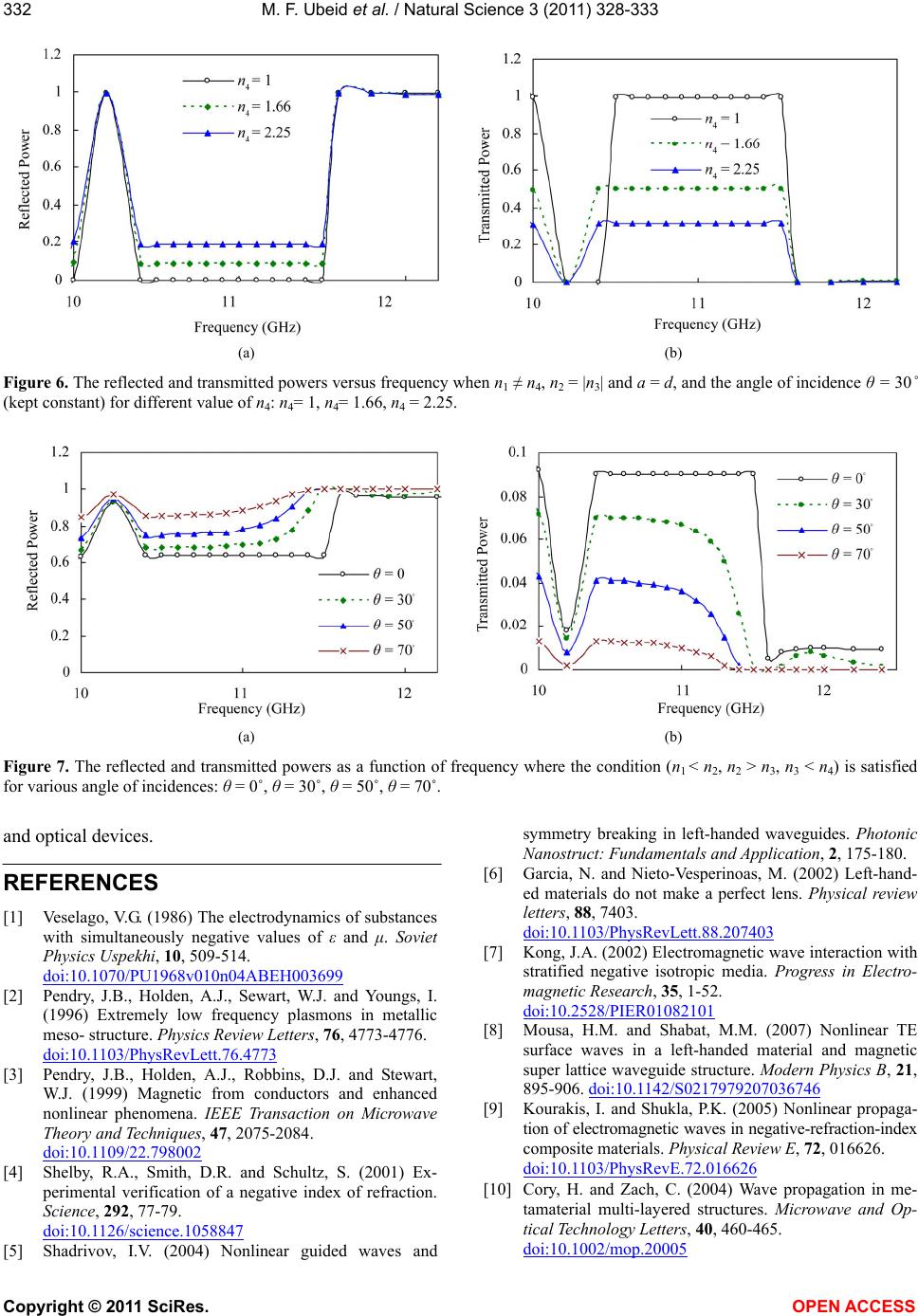 M. F. Ubeid et al. / Natural Science 3 (2011) 328-333 Copyright © 2011 SciRes. OPEN ACCESS 332 (a) (b) Figure 6. The reflected and transmitted powers versus frequency when n1 ≠ n4, n2 = |n3| and a = d, and the angle of incidence θ = 30˚ (kept constant) for different value of n4: n4= 1, n4= 1.66, n4 = 2.25. (a) (b) Figure 7. The reflected and transmitted powers as a function of frequency where the condition (n1 < n2, n2 > n3, n3 < n4) is satisfied for various angle of incidences: θ = 0˚, θ = 30˚, θ = 50˚, θ = 70˚. and optical devices. REFERENCES [1] Veselago, V.G. (1986) The electrodynamics of substances with simultaneously negative values of ε and μ. Soviet Physics Uspekhi, 10, 509-514. doi:10.1070/PU1968v010n04ABEH003699 [2] Pendry, J.B., Holden, A.J., Sewart, W.J. and Youngs, I. (1996) Extremely low frequency plasmons in metallic meso- structure. Physics Review Letters, 76, 4773-4776. doi:10.1103/PhysRevLett.76.4773 [3] Pendry, J.B., Holden, A.J., Robbins, D.J. and Stewart, W.J. (1999) Magnetic from conductors and enhanced nonlinear phenomena. IEEE Transaction on Microwave Theory and Techniques, 47, 2075-2084. doi:10.1109/22.798002 [4] Shelby, R.A., Smith, D.R. and Schultz, S. (2001) Ex- perimental verification of a negative index of refraction. Science, 292, 77-79. doi:10.1126/science.1058847 [5] Shadrivov, I.V. (2004) Nonlinear guided waves and symmetry breaking in left-handed waveguides. Photonic Nanostruct: Fundamentals and Application, 2, 175-180. [6] Garcia, N. and Nieto-Vesperinoas, M. (2002) Left-hand- ed materials do not make a perfect lens. Physical review letters, 88, 7403. doi:10.1103/PhysRevLett.88.207403 [7] Kong, J.A. (2002) Electromagnetic wave interaction with stratified negative isotropic media. Progress in Electro- magnetic Research, 35, 1-52. doi:10.2528/PIER01082101 [8] Mousa, H.M. and Shabat, M.M. (2007) Nonlinear TE surface waves in a left-handed material and magnetic super lattice waveguide structure. Modern Physics B, 21, 895-906. doi:10.1142/S0217979207036746 [9] Kourakis, I. and Shukla, P.K. (2005) Nonlinear propaga- tion of electromagnetic waves in negative-refraction-index composite materials. Physical Review E, 72, 016626. doi:10.1103/PhysRevE.72.016626 [10] Cory, H. and Zach, C. (2004) Wave propagation in me- tamaterial multi-layered structures. Microwave and Op- tical Technology Letters, 40, 460-465. doi:10.1002/mop.20005 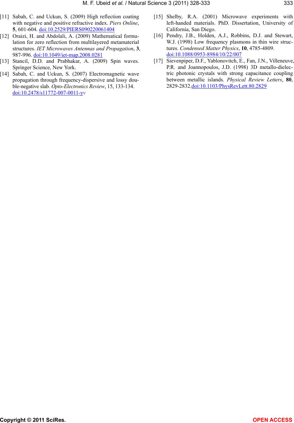 M. F. Ubeid et al. / Natural Science 3 (2011) 328-333 Copyright © 2011 SciRes. OPEN ACCESS 333 [11] Sabah, C. and Uckun, S. (2009) High reflection coating with negative and positive refractive index. Piers Online, 5, 601-604. doi:10.2529/PIERS090220061404 [12] Oraizi, H. and Abdolali, A. (2009) Mathematical formu- lation for zero reflection from multilayered metamaterial structures. IET Microwaves Antennas and Propagation, 3, 987-996. doi:10.1049/iet-map.2008.0281 [13] Stancil, D.D. and Prabhakar, A. (2009) Spin waves. Springer Science, New York. [14] Sabah, C. and Uckun, S. (2007) Electromagnetic wave propagation through frequency-dispersive and lossy dou- ble-negative slab. Opto-Electronics Review, 15, 133-134. doi:10.2478/s11772-007-0011-yv [15] Shelby, R.A. (2001) Microwave experiments with left-handed materials. PhD. Dissertation, University of California, San Diego. [16] Pendry, J.B., Holden, A.J., Robbins, D.J. and Stewart, W.J. (1998) Low frequency plasmons in thin wire struc- tures. Condensed Matter Physics, 10, 4785-4809. doi:10.1088/0953-8984/10/22/007 [17] Sievenpiper, D.F., Yablonovitch, E., Fan, J.N., Villeneuve, P.R. and Joannopoulos, J.D. (1998) 3D metallo-dielec- tric photonic crystals with strong capacitance coupling between metallic islands. Physical Review Letters, 80, 2829-2832.doi:10.1103/PhysRevLett.80.2829 |