

Paper Menu >>
Journal Menu >>
 Journal of Computer and Communications, 2014, 2, 36-41 Published Online May 2014 in SciRes. http://www.scirp.org/journal/jcc http://dx.doi.org/10.4236/jcc.2014.27006 How to cite this paper: Urban, F. (2014) Optimization of the Tilted Fibre Bragg Gratings for the Fibre Accelerometric Sensor. Journal of Computer and Communications, 2, 36-41. http://dx.doi.org/10.4236/jcc.2014.27006 Optimization of the Tilted Fibre Bragg Gratings for the Fibre Accelerometric Sensor Frantisek Urban1,2 1Dept of Microelectronics, Brno University of Technology, FEEC, Brno, Czech Republic 2Network Group, s.r.o., Brno, Czech Republic Email: [email protected], [email protected] Received January 2014 Copyright © 2014 by authors and Scientific Research Publishing Inc. This work is licensed under the Creative Commons Attribution International License (CC BY). http://creativecommons.org/licenses/by/4.0/ Abstract The presentation shows the principle and construction of the fibre optic accelerometric sensor. The sensor element is based on the use of the tilted fibre Bragg grating (TFBG) that is imprinted to the bend insensitive single-mode telecommunication grade fibre. The fibre section with TFBG is then coupled to the evaluation fibre circuit with the cladding-core mode conversion element that provides the core re-coupling of the optical power injected by TFBG to the fibre cladding. The cladding-core mode conversion efficiency is sensitive to the acceleration generated fibre bending. It is shown that the sensitivity of the device depends on the rate of the main core reflection versus cladding ghost reflection induced by the grating. The analysis of the core reflection power coupl- ing on the angle of the grating tilt and the analysis of the cladding ghost reflection power coupling on the angle of the grating tilt is presented and the optimal parameters of the tilt and refractive index modulation are derived. The presentation gives the experimental results of the TFBG sensor prepared according to the optimization process. Keywords Optical Fibre, Tilted Fibre Bragg Grating, Accelerometric Sensor, Cladding Modes, Reflected Spectrum 1. Introduction Fibre optic accelerometric sensors are one of the applications of the optical fibres where the tilted Bragg gratings can find the utilization. The principle of the fibre optic accelerometric sensor with the tilted Bragg grating is shown in the Figure 1. The sensor element is based on the use of the tilted fibre Bragg grating (TFBG) that is imprinted to the bend insensitive single-mode telecommunication grade fibre. The fibre section with TFBG is then coupled to the 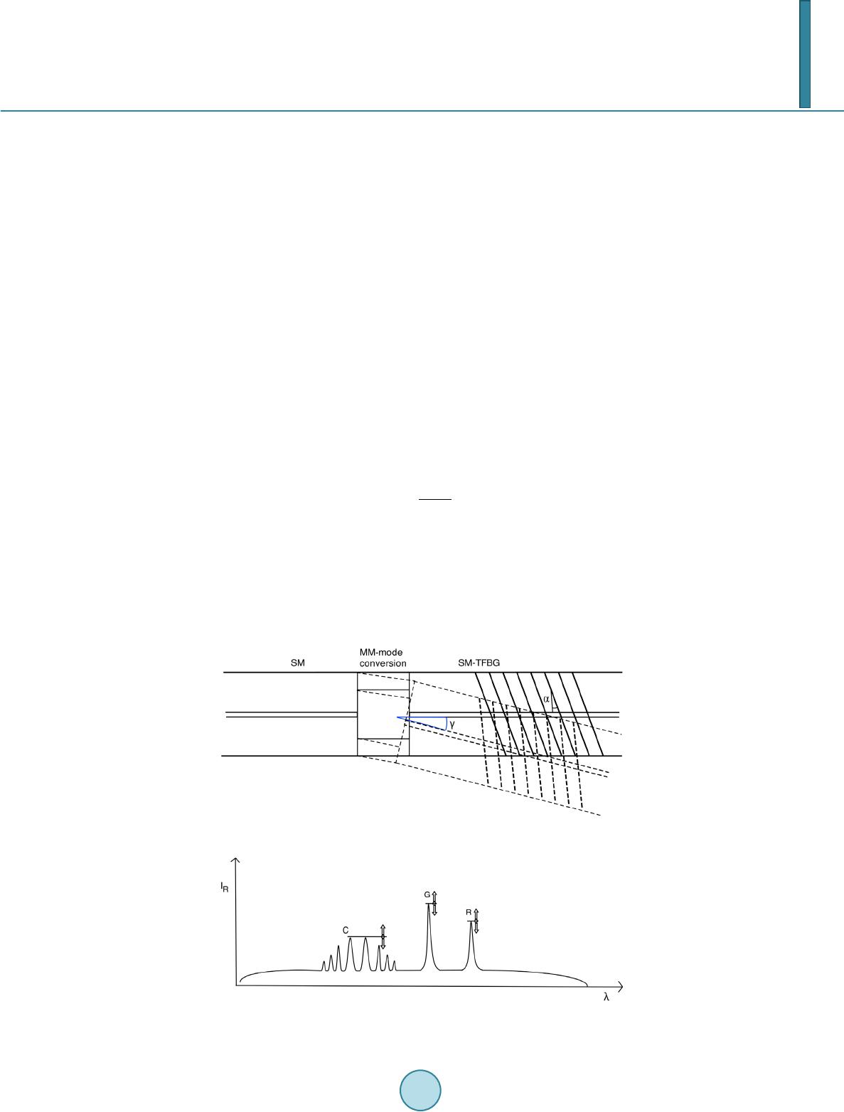 F. Urban 37 evaluation fibre circuit with the cladding-core mode conversion element that provides the core re-coupling of the optical power injected by TFBG to the fibre cladding. As the mode conversion element the section of the graded index multimode fibre with core/cladding diameters of 62.5/125 microns and the specific length was selected. The cladding-core mode conversion efficiency of the light passing through the multimode fibre section is sensi- tive to the acceleration generated fibre bending and for suitable length of the multimode section it grows with the angle γ. Similarly, the transmission of TFBG reflected core mode through the multimode section is inversely affected by the angle γ. Thus, the use of TFBG allows for relative signal amplitude evaluation where the bending angle γ is derived from either the ratio of the cladding and reflected core mode powers or from the ratio of the ghost and reflected core mode powers. The powers of light confined in reflected core mode, ghost and cladding modes are spectrally separated, as shown in the Figure 2, and can be measured individually. The relative signal amplitude measurement allows for the elimination of any light source intensity noise or instabilities and gives increased sensibility. On the other hand, the relative measurement requires the design of TFBG that gives com- parable amplitudes of core reflection versus the ghost or the cladding modes. The following paragraphs deal with that issue. 2. Tilted Grating Reflections The behaviour of the TFBG with broadband incident light represents a complex issue. First, the core reflection propagating opposite to the incoming incident core mode still exists and its amplitude changes with the grating tilt. The maximum amplitude is obtained when the grating planes are perpendicular to the fibre axis. The grating tilt α also causes the frequency shift of the core reflection λα that migrates towards the longer wavelengths. 0 2 cos α λα ⋅Λ = Then, the tilted planes of the grating reflect some spectral parts of the coming light to the first order cladding mode called “ghost” and to the series of higher order cladding modes. Dislike the core reflection that propagates along the axis of the fibre, the ghost and cladding modes have each other their own angle of propagation βi with respect to the fibre asis. These angles are pertinent to the fibre core/cladding structure and are only weekly af- fected by the grating. Both the ghost and the cladding modes are shifted towards the shorter wavelengths, the shorter the higher is the mode characteristic angle of propagation Figure 1. Principle of Accelometric sensor. Figure 2. Spectrum view of reflected light in SM-MM-TFBG structure. 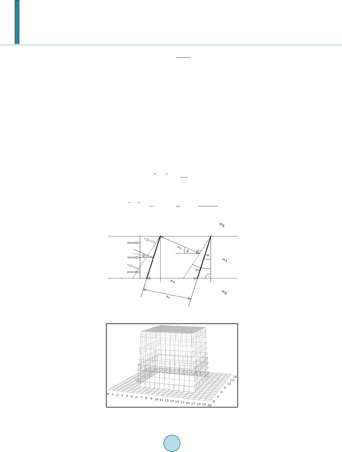 F. Urban 38 0 cos 2cos i i β β λα = Λ Maximum amplitude of the light reflected to the ghost or cladding mode is achieved when the tilt of the grat- ing planes coincides with the optimum tilt angle αopt = β/2. The situation is shown in the Figure 3. When the re- flecting planes do not posses the angle αopt then the reflected light from the different sections of the cross section of the fibre core gets the phase shifts that, conclusively, leads to the decreasing of the energy coupling from the incident core mode to the desired reflected mode. 3. Cladding Coupling Models The cladding mode coupling efficiency is affected by the above mentioned cross section phase shift and by the cross section mode field intensity distribution. To simplify the calculation we have set three model of the fibre fundamental core mode distribution and from these premises we have figured out the expressions giving the relative reflection efficiency against the grating tilt angle α. The first model counts with the equal distribution of the incident mode light intensity within the interval <-a/2|x, y a/2>, where a variable represents the physical diameter of the fibre core, see the Figure 4. The cou- pling efficiency factor for this supposition is: 22 00 0 2 cos sin aa a K dxy πα = Λ ∫∫ The second model is represented by the cosine intensity distribution in the fibre core, again in the interval 22 00 0 ππ 2πsin coscos cos aa b Kxdxyy dy aa α = ⋅⋅ Λ ∫∫ Figure 3. Reflected wave from tilted gratings. Figure 4. Model 1—incident light intensity distribution. 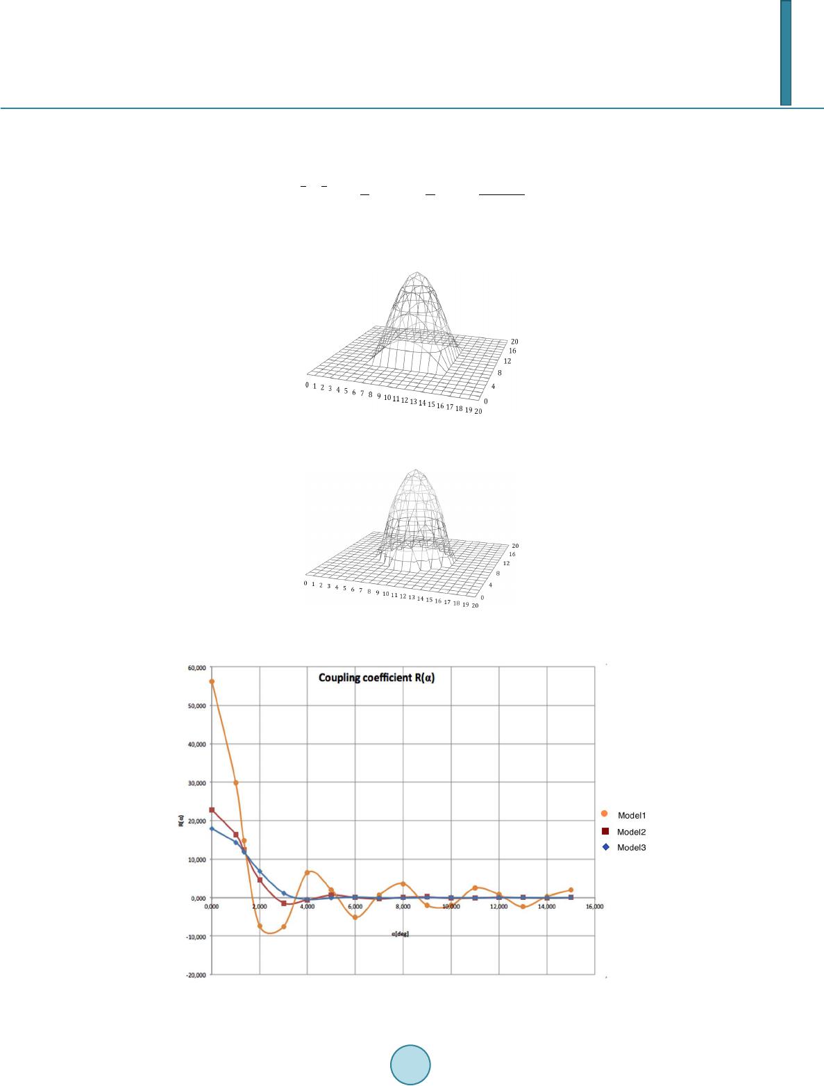 F. Urban 39 <-a/2|x, y|a/2>,, see the Figure 5. The coupling efficiency factor for this supposition is: The third model uses the modification of the second one. The cosine core intensity distribution is cut to the area of rhomb as seen in the Figure 6. The coupling efficiency factor for this supposition is: 22 00 0 ππ 2πsin coscos cos aa y c Kxdxyy dy aa α − = ⋅⋅ Λ ∫∫ The resulting curves for the coupling efficiencies to the core reflection mode for all three models with respect to the tilt angle α are shown in the Figure 7. Experimental results obtained by analysing the TFBGs exposed to Figure 5. Model 2—incident light inten- sity distribution. Figure 6. Model 3—incident light inten- sity distribution. Figure 7. Coupling efficiency evaluation. 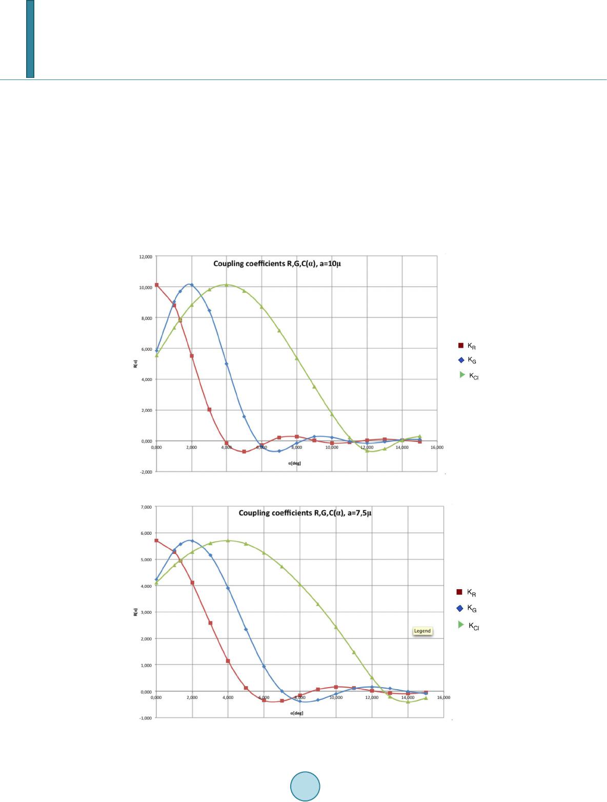 F. Urban 40 the hydrogenated G.657A fibres with different angles showed the best match of the second model. Using the second model, we have evaluated the graphs of the coupling efficiency to the core reflection, ghost and dominant higher order cladding mode. The curves depend greatly on the fibre core diameter, and it is seen clearly from the comparison of the curve sets for 10µ and 7.5µ fibre cores, see Figure 8 and Figure 9 that the high efficiency of coupling to the high order modes can be strongly boosted when selecting the tiny core fibre where the higher tilt angles of the TFBG make sense. 4. Conclusions According to the results obtained by the above analysis we have selected the optimum angle of tilt for the TFBG used in the design of the fibre vibration sensor with relative amplitude evaluation. So that to get the Ghost to Core reflection intensity rate of 2:1 ve have selected the tilt angle of 2˚. The Figure 10 shows the resulting transmission spectrum of the FTBG designed and exposed accordingly. Figure 8. Coupling coefficients for 10µ fibre core. Figure 9. Coupling coefficients for 7.5µ fibre core. 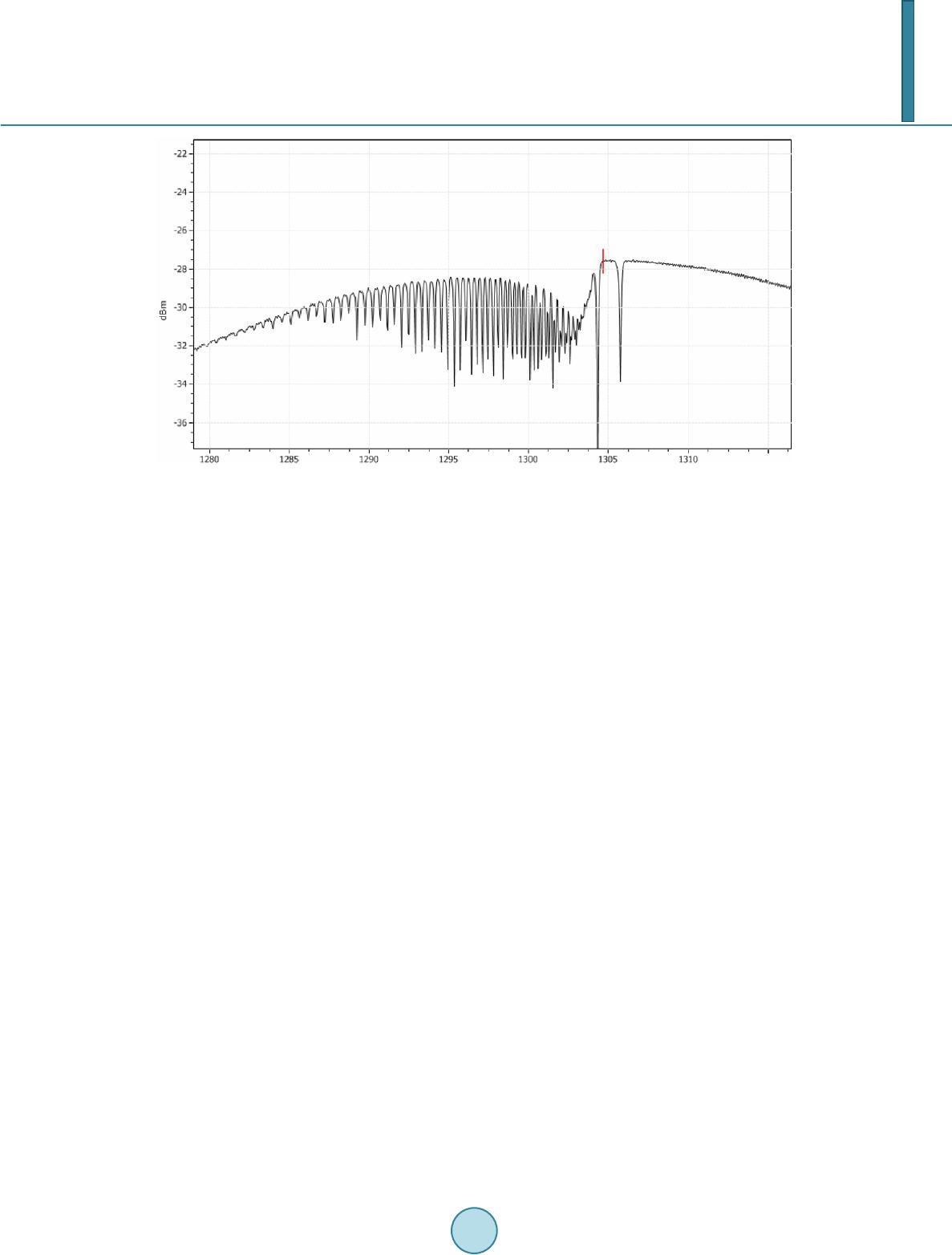 F. Urban 41 Figure 10. Resulting transmission spectrum of the FTBG. Acknowledgements This research has been supported by Technology Agency of the Czech Republic under contract TA03010835 “Fiber optic sensors for industrial applications”. References [1] Urban, F. (2012) Mící pracovišt pro analýzu vlastností vláknových mížek. FEKT VUT BRNO, Brno. [2] Jacques, A., Shao , L.Y. and Caucheteur, C. (2013) Tilted fiber Bragg Grating Sensor. Laser Photonics Reviews, 7, 83- 108. [3] Kashyap, R. (1999) Fiber Bragg Gratings. Academic Press, Sand Diego. [4] Othonos, A. and Kalli, K. (1999) Fiber Bragg Gratings, Fundamentals and Applications. Artech House, Notwood. |