

Paper Menu >>
Journal Menu >>
 Journal of Applied Mathematics and Physics, 2014, 2, 405-410 Published Online May 2014 in SciRes. http://www.scirp.org/journal/jamp http://dx.doi.org/10.4236/jamp.2014.26048 How to cite this paper: Zhan, Y.X. and Park, T.S. (2014) Effect of Insulated Oblique Plates on Heat Transfer and Recirculat- ing Flow in a Channel. Journal of Applied Mathematics and Physics, 2, 405-410. http://dx.doi.org/10.4236/jamp.2014.26048 Effect of Insulated Oblique Plates on Heat Transfer and Recirculating Flow in a Channel Yinxiao Zhan, Tae Seon Park School of Mechanical Engineering, Kyungpook National University, Daegu, South Korea Email: [email protected] Received March 2014 Abstract Flow and heat transfer characteristics of a channel with oblique plates which are mounted pe- riodically on the channel wall have been numerically investigated in a laminar range. The main objective of the present study is to find the effect of the tilt angle of oblique plate on pressure drop and heat transfer characteristics in unsteady states. To get the different conditions of the heat transfer and flow evolution, two key parameters of the Reynolds number and the tilt angle of ob- lique plate are considered. At Re200, 600= , the tilt angles are changed for the range of 50˚ - 13 0˚. The computational results show that the heat transfer and pressure drop are strongly dependent on the tile angle and Reynolds number. When the flows are unsteady, the tilt angle has an impor- tant role in the heat transfer enhancement. Oscillatory structures induce the better mixing of the therm al field and promote the wall heat transfer. For a constant plate length, the wall heat trans- fer is maximized near the 90˚ - 100˚. This is strongly coupled with the variations of flow mixing induced by the oblique plate. Keywords Heat Transfer Enhancement, Reynolds Num ber , Flow Oscill atio n 1. Introduction In general, when the flow in a channel is destabilized by periodic disturbance promoters, the heat transfer is sig- nificantly changed [1]. This technique has been frequently adopted for heat transfer devices because the promo- ter enhances the wall heat transfer. Several studies of oscillatory flow and heat transfer in a channel were carried out. Valencia [2] [3] investi- gated flow structure and heat transfer in a channel with periodically mounted transverse vortex generators in the Reynolds number range of steady to oscillatory flow. They found self-sustained oscillations enhanced mixing between the core fluid and the fluid near the wall. Saha and Acharya [4] analyzed the unsteady three-dimen- sional flow and heat transfer in a pin-fi n heat exchanger. They showed the heat transfer is enhanced significantly when the flow becomes unsteady. Guzman and Valle [5] investigated a transition scenario of two Hopf bifurca-  Y. X. Zhan, T. S. Park 406 tions when the flow evolves from a laminar to a time-dependent periodic and then to a quasi-periodic flow. And the increase of the Nusselt number is higher for a quasi-periodic than for a periodic flow regime. On the other hand, the flow structure and heat transfer in a channel attached the rib is investigated by several researchers. Sriharsha et al. [6] discussed the influence of rib height on the local heat transfer distribution and pressure drop in a channel with 90˚ continuous and 60˚ V-broken ribs. They indicated that the heat transfer augmentations caused by 60˚ V-broken ribs are higher than those of 90˚ continuous attached ribs. But as the rib height increases, the enhancement by the broken ribs is decreased. Tanda [7] [8] studied flow and heat transfer in a rectangular channel with 45˚ angle rib on one/two walls. They showed that secondary responsible for heat transfer performance are presented. The effects of Reynolds number and tilt angle of the oblique plate attached to the upper wall of the channel were studied numerically by using the finite volume method. The tilt angle is changed for the range of 50˚ - 130˚ and plate length is selected as 0.4 H. Here, H is the channel hei g ht. The present study is to elucidate the effects of tilt angle of the oblique plate on heat transfer and pressure drop for various Reynolds number. 2. Numerical Methods and Flow Condition 2.1. Governing Equation The flow is two-dimensional with constant properties. The x-axis is taken in the flow direction and the y-axis is perpendicular to the flow direction. The flow is assumed to be laminar and incompressible. Buoyancy force is neglected. The governing equations for continuity, momentum and temperature are given by ( )0 i i U x ρ ∂= ∂ (1) 11 ()[ ()] j ii ij i jijj i U UU P UU F t xxxxx ρ µδ ∂ ∂∂ ∂ ∂∂ +=+ ++ ∂∂∂∂∂ ∂ . (2) () () i j jj TT UT txxpr x µ ρ ∂∂∂ ∂ += ∂∂∂ ∂ . (3) 1 F represents the streamwise mean pressure gradient, which needs to be calculated dynamically in order to maintain a constant mass flow rate and 1i δ is the kronecker delta. 2.2. Numerical Methods and Boundary Condition The spatial discretization is performed with the fourth-order compact scheme The viscous term and the other terms are evaluated by the fourth-order central difference. A nonstaged grid arrangement is adopted and the momentum interpolation technique is employed to avoid pressure-velocity decoupling. The PISO algorithm is employed for pre ssure-velocity coupling [9]. The momentum and energy equations are solved with second-or- der upwind scheme. Periodic boundary condition with constant mass flow rates is specified at the inlet and out- let of the channel. No-slip and constant wall temperature conditions are specified on the upper and lower walls of the channel. Oblique plate is insulated. In order to assess the accuracy of these computations, the grid inde- pendence is carried out in the analysis by adopting different grid distributions of 150 × 60, 170 × 80, 200 × 100 and 230 × 120. The grid systems of 220 × 120 show a satisfactory solution. 2.3. Configuration Figure 1 shows the flow geometry and the coordinate system. It is consisted of two walls channel of height H with insulated a thin oblique plate (t = 0.02 H) on the upper wall. Upper and lower walls are maintained at a constant temperature. The lengths of the oblique plates is 0.4 H , channel height is H. The periodicity length L is 2.5 H . For all cases, the inclination angle of the plates varies from 50˚ to 130˚ with an increment of 10˚. To validate of the present numerical method, the numerical results of Cheng and Huang [10] are compared with the present result (not shown in here). The present numerical prediction shows a very good agreement with the numerical results of Cheng and Huang. So, this provides a strong confidence in further investigation of channel flow with the oblique plate. 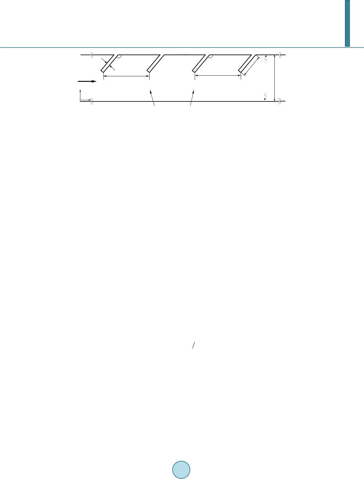 Y. X. Zhan, T. S. Park 407 Figure 1. Flow configuration. 3. Results and Discussion Figure 2 shows time mean streamlines and temperature contours for α = 50˚, 70˚, 90˚, 130˚, respectively, at Re 200 = . Recirculation regions are identified between the baffles for all tilt angle. Center of the recirculation is moved to the downstream due to the effect of the oblique plate tilt angle. Instantaneous streamlines and temper- ature contours during one time period of flow are presented in Figure 3 at Re 600= , α = 50˚, 90˚. It can be seen that vortices induced by oblique plate along the walls remove to the downstream. The main stream moves toward the upper and lower walls in an alternating manner. At the same time, the counter-rotating vortices are also generated along the lower wall by the oblique plate. Compared with the α = 50˚ and α = 90˚, larger size of vortices are formed and the number of the vortices is increased for the case of α = 90˚. As the result, more active mixing and scalar transport are induced. The wall heat transfer depends on the geometrical condition. Figure 4 shows the Nusselt number for different tilt angles, as Re increase. The local Nusselt number is defined as follows: (/) /() bw NuTy HTT=∂∂ − . The mean Nusselt number along the channel wall is expressed by integrating the local Nu on the channel wall: 0 1/ L avg NuL Nudx= ∫ As can be seen that, Nu is increased as increasing Re . In steady state, the variation of Nu is not sensitive to the tilt angle. But as Re increases, the local Nu is strongly depends on the tilt angle. For small Re , the recirculating flow reduces the local Nu because it makes the thermal boundary layer thicker (see Figure 2). For larger Re, size and number of the vortex plays major role for heat transfer enhancement (see Figure 3). We can see that Nu is maximized at 90 α ≈° . This paper is to present the effect of the tilt angle on flow structure and heat transfer. Figure 5 shows distri- bution of time-averaged local Nu , time-averaged local skin friction coefficient f C and time-averaged pres- sure coefficient p C along upper wall at Re 600= . The value of f C reflects the appearance of flow separa- tion and reattachment. The peak is related to the accelerated flow caused by positive vorticities near the upper wall. It shifts from downstream to upstream as increasing the tilt angle. This represents that the vortical region varies with the tilt angle. In the vicinity of 90˚, the oblique plate generates a flow pattern characterized by high velocity and velocity gradients, which generate higher shear stresses, consequently, a higher friction coefficient. Therefore, the peaks of Nu are strongly related to the local maximum of f C . To show pressure distribution on the upper wall, pressure coefficient, defined as 2 () / (12) p refm C ppU ρ = − where p is the static pressure on the wall and ref p is a reference pressure. The pressure on the upper wall drastically increases as tilt angle increases to 90˚. It demonstrates that flow should be strongly dependent upon tilt angle. Figure 6 presents the distribution of time-averaged pressure coefficient p C along the upper wall for α = 50˚, 90˚. For both cases, they have a similar distribution trend, near the upstream plate pressure is decreased as Re increases, however, when flow move towards next plate, pressure is increased with increasing Re . It is clear that the pressure drop of the α = 90˚ along the upper wall is larger than that of the α = 50˚ at the same Re . It is interesting that the flow at / 0.1xL H= for α = 90˚, experiences strong acceleration and favorable pressure gradient. This trend remains until / 0.5xL H= and then the pressure becomes adverse in the rest of the wall. This pressure distribution gives more steep velocity gradient. It results in the enhanced the heat transfer. In order to demonstrate the effect of the oblique plate on flow field, Figure 7 shows root mean square of ver- tical velocity fluctuation ( rms V ) along the connection between the two tips of the neighboring oblique plate at H L α dT w1 T w2 x y α Flow t periodic boundaries computational domain L 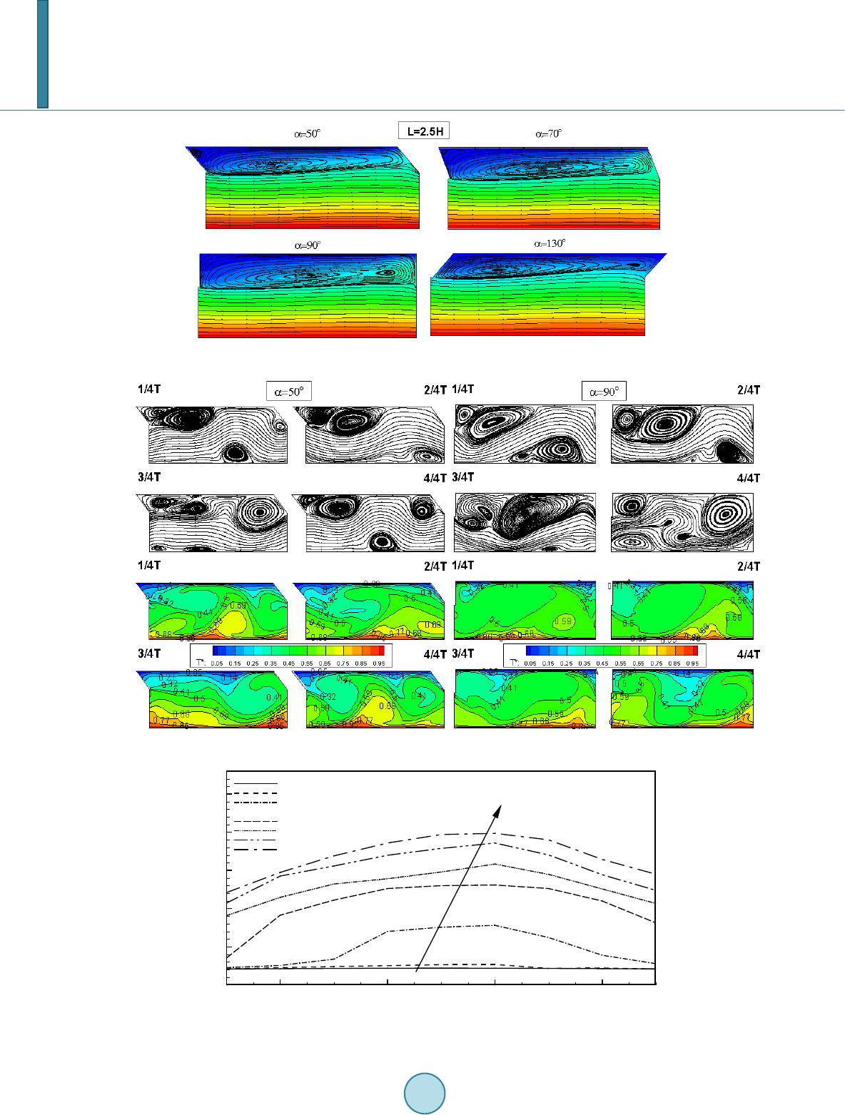 Y. X. Zhan, T. S. Park 408 Figure 2. Streamlines and temperature fo r α = 50˚, 70˚, 90˚, 130˚, Re = 200. Figure 3. Instantaneous streamlines and temperature contours during one period for α = 50˚, 90˚, Re = 600. Figure 4. Average Nusselt number for different Re and tilt angle. α Nu avg 6080100 120 0 10 20 Re=1 00 Re=2 00 Re=3 00 Re=4 00 Re=5 00 Re=6 00 Re=7 00 Re=8 00 Re 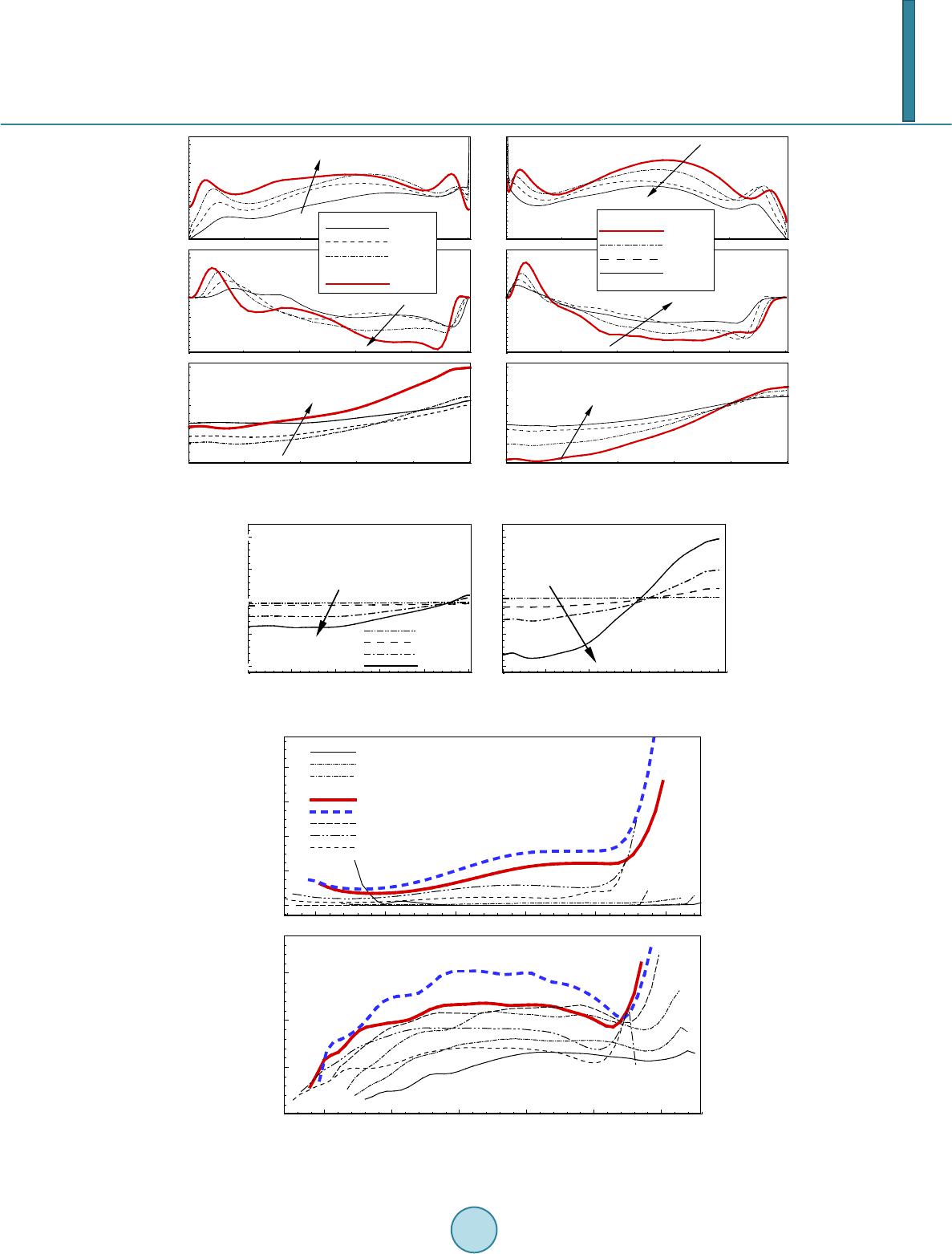 Y. X. Zhan, T. S. Park 409 Figure 5. The mean Nu , skin friction coefficient and pressure coefficient on the on the upper wall (Re = 600). Figure 6. Pressure coefficient along the upper wall for different Re. Figure 7. Vertical velocity fluctuation at the tip of oblique plate. Cf 0.5 1 1.5 2 2.5 -1E-05 0 1E-05 90 ο L/H Cp 0.5 1 1.5 2 2.5 -0.0005 0 0.0005 90 ο 0 0.51 1.52 2.5 0 10 20 130 ο N u 0 0.51 1.52 2.5 0 10 20 90 ο 0.5 1 1.5 2 2.5 -1E-05 0 1E-05 130 ο L/H 0.5 1 1.5 2 2.5 -0.0005 0 0.0005 130 ο α=100ο α=110ο α=120ο α=130ο α=50 ο α=60 ο α=70 ο α=80 ο α=90 ο L/H 0 0.5 1 1.5 2 2.5 -0.001 0 0.001 α=90 ο Re L/H C p 0.5 1 1.5 2 2.5 -0.001 0 0.001 Re=200 Re=400 Re=600 Re=800 α=50 ο Re L/H V rms 00.5 1 1.5 2 2.5 0 0.0006 α=50 ο α=60 ο α=70 ο α=80 ο α=90 ο α=100 ο α=110 ο α=120 ο α=130 ο Re=200 L/H V rms 0 0.5 1 1.5 2 2.5 0 0.015 Re=600  Y. X. Zhan, T. S. Park 410 Re 200,= 600 . It is clearly seen that the vertical velocity fluctuation suddenly increases when α = 90˚, 100˚ for both Re200, 600= . It means that obstruction of the flow due to the oblique plate is more severe. It induces flow sweep motion to the lower wall or imping to the upper wall. The variations of , rms V according to the tilt angles well are very similar the change of avg Nu in Figure 4. 4. Conclusion Fluid flow and heat transfer characteristics of channel flow with oblique plate have been numerically investi- gated by the finite volume method. The computational results show that the heat transfer and pressure drop are strongly dependent on the different tilt angle and Reynolds number. In the steady state, the effect of the tilt angle on the heat transfer and pressure drop is not obvious. But when the flow becomes in the unsteady state, tilt angle affects significantly on the heat transfer enhancement and pressure drop. Because when tilt angle is 90 α ≈ , the strong vertical velocity fluctuations and steep velocity gradients along the channel wall are induced. This struc- ture induces a better mixing of the thermal field and promotes the wall heat transfer. References [1] A mon, C.H., Majumdar, D., Herman , C.V., M ayinger, F., Mikic, B.B. and Sekulic, D.P . (1992) Numerical and Expe- rimental Studies of S elf-Sustained Oscillatory Flows in Communicating Channels. International Journal of Heat and Mass Transfer, 35, 3115-3129. http://dx.doi.org/10.1016/0017-9310(92 )90 33 1 -L [2] V alenci a, A. (19 99 ) Heat Transfer Enhancement Due to Sel f-Sustained Oscillating Transverse Vortices in Channels with Periodically Mounted Rectangular Bars. International Journal of Heat and Mass Transfer, 42, 2053-2062. http://dx.doi.org/10.1016/S0017-9310(98)00295-6 [3] V alenci a, A. and Sen , M. (2003 ) Unsteady Flow and Heat Transfer in Plane Channels with Spatially Periodic Vortex Generato rs. International Journal of Heat and Mass Transfer, 46, 3189-3199. http://dx.doi.org/10.1016/S0017-9310(03)00099-1 [4] Sah a, A. K. and Acharya, S. (200 3) Parametric Study of Unsteady Flow and Heat Transfer in a Pin-Fin Heat Exchanger. International Journal of Heat and Mass Transfer, 46, 3815-38 30. http://dx.doi.org/10.1016/S0017-931 0(03 )00 19 0-X [5] Amado r, M.G. and Marcelo, D.V. (2006) Heat Transfer Enhancement in Grooved Channels Due to Flow Bifurcations. International Journal of Heat and Mass Transfer, 42, 967-975 . http://dx.doi.org/10.1016/j.ijheatmasstransfer.2009.02.026 [6] SriHarsh a, V., Prabh u, S.V. and Vedula, R.P. (2009) Influence of Rib Height on the Local Heat Transfer Distribution and Pressure Drop in a Square Channel with 90 Continuous and 60, V-Broken Ribs. Applied Thermal Engineering, 29, 2444-2459. http://dx.doi.org/10.1016/j.applthermaleng.2008.12.015 [7] Tanda, G. (2004) Heat Transfer in Rectangular Channels with Transverse and V-Shaped Broken Ribs. International Journal of Heat and Mass Transfer, 47, 229 -243. http://dx.doi.org/10.1016/S0017-9310( 03) 0041 4 -9 [8] Tanda, G. (2011) Effect of Rib Spacing on Heat Transfer and Friction in a Rectangular Channel With 45 ° Angled Rib Turbulators on One/Two Walls. International Journal of Heat and Mass Transfer, 54, 1081-1090. http://dx.doi.org/10.1016/j.ijheatmasstransfer.2010.11.015 [9] P ark, T.S. (2006) Effects of Time-Integration Method in a Large-Eddy Simulation Using the PISO Algorithm: Part Ι-Flow Field. Numerical Heat Transfer, Part A, 50, 229 -245. http://dx.doi.org/10.1080/10407780600602374 [10] Cheng, C.H. and Huang, W.H. (1991) Numerical Prediction for Laminar Forced Convection in P ar allel-Plate Channels with Transverse Fin Arrays. International Journal of Heat and Mass Transfer, 34, 2739 -2749 . http://dx.doi.org/10.1016/0017-9310(91)90232-4 |