

Paper Menu >>
Journal Menu >>
 Journal of Applied Mathematics and Physics, 2014, 2, 342-348 Published Online May 2014 in SciRes. http://www.scirp.org/journal/jamp http://dx.doi.org/10.4236/jamp.2014.26041 How to cite this paper: Tang, W., Wang, W.J., Wang, Y. and Li, Q. (2014) Fatigue Strength and Modal Analysis of Bogie Frame for DMUs Exported to Tunisia. Journal of Applied Mathematics and Physics, 2, 342-348. http://dx.doi.org/10.4236/jamp.2014.26041 Fatigue Strength and Modal Analysis of Bogie Frame for DMUs Exported to Tunisia Wei Tang*, Wenjing Wang, Yao Wang, Qiang Li School of Mechanical Electronic and Control Engineering, Beijing Jiaotong University, Beijing 100044, China Email: *[email protected] Received January 2014 Abstract The equivalent stress at key positions of Bogie Frame for DMUs Exported to Tunisia is obtained by using simulation analysis. The evaluation of static strength and fatigue strength is checked refer- ring to UIC specification and Goodman sketch for welding materials. In addition, the modal analy- sis of the frame is made, and the vibrational modal of frame in given frequency domain is prede- termined to evaluate the dynamical behavior of the frame in order to meet the dynamical design requirements. The results show that the key points of the calculated frame of the equivalent stress are less than allowable stress, and thus it could provide a theoretical foundation for the optimized design of frame structure and safety of industrial production. Keywords Fatigue St reng th , Diesel Multiple Units, Frame, Finite Element, Modal An alysis 1. Introduction The bogie frame is the main load bearing components and power transmission components of the vehicle, when the vehicle is in motion the process, not only to the bogie frame to withstand loads, but also need to pass a va- riety of forces between the body and the wheel. Due to the fatigue test costs are expensive, the fatigue strength assessment of key components in the bogie frame using finite element model can find out the fatigue strength of the weak parts, can reduce the risk of fatigue testing prototypes, shorten development cycles, reduce trial costs. In addition, the current domestic commonly uses Electric Multiple Units [1], lacks of bogie products of Diesel Multiple Units; Diesel Multiple Units still have a large market in many countries such as Tunisia for its poor line conditions and economic factors. Therefore, strength analysis and dynamic assessment for the bogie frame of Diesel Multiple Units is of great significance. This paper is to understand the export Tunisia DMUs bogie basic components, infrastructure characteristics, determined the type of bogie frame load sources and calculated in accordance with the relevant specifications to determine the load; then to use the Hyper mesh software architecture network entities meshing, to re-use the ANSYS finite element analysis software for finite element analysis of the bogie frame. The evaluation of static strength and fatigue strength is checked referring to UIC specification and Goodman sketch for welding mate- rials. In addition, the modal analysis of the frame is made [2]. * Corresponding author. 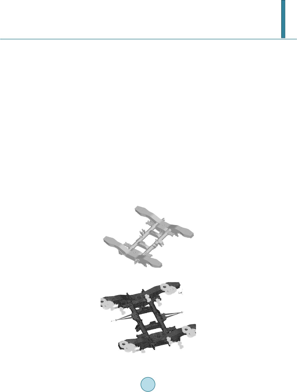 W. Tang et al. 343 2. Bogie Frame Structure and Finite Element Modeling 2.1. Bogie Frame Structure The bogie Frame for DMUs Exported to Tunisia is adopted by welded structure, Figure 1 demonstrates that the main framework architecture is H-shaped in the horizontal plane, which is composed of two box-shaped side sills, the overall composition of the box beam welding, by the central concave belly of the fish box structure composed of a spring seat side beam welding, basic brake mounts, anti-roll torsion bar seat, etc., the cavity has a thickness of 10 mm stiffener plate [3]. Box beam structure for the central opening, the transverse beam welding has ended with stopper seat, traction rod seat, motor bracket, gearbox bracket and secondary lateral damper seat and so on. 2.2. FEM Model of Bogie Frame Considering calculating workload, precision and the actual situation in structure of the entire bogie frame, this research selects 10-node solid element of solid 92. Based on the model, the entire bogie frame is discrete with the software Hyper mesh and analyzed with the large generally used finite element software ANSYS [4]. In or- der to simulate the real boundary conditions of the bogie frame, axle box spring in the bogie frame mount simu- lated by a series of axle box spring unit Combine14 spring means, consistent with the axle box spring stiffness of the spring element stiffness. In the end, the finite element discrete nodes of 110,368, the number of units to 341,334, finite element discrete model shown in Figure 2. 2.3. Evaluating Standard of Bogie Frame Strength In the fatigue strength of welded bogie frame has now formed the international standard UIC 615-4 [5] as the representative of the design, evaluation system. Bogie frame structure strength assessment generally includes three aspects, namely, the role of analysis to determine the load, static strength analysis and assessment, analysis and evaluation of the fatigue strength. Figure 1. Welded bogie frame. Figure 2. The FEM model of the bogie frame.  W. Tang et al. 344 According to the UIC 615-4 regulations, we can calculate the appropriate supernormal load, simulated opera- tional load and special operational load. Supernormal load when the maximum load operations may occur; si- mulate actual operating load refers to the load operations occur frequently; special operational load refers to the load frame by a special device caused. In the practical constraints are consistent with the principles of the frame, and the constraints of the axial knuckle arm spring constraints loads. Then, referring to the UIC 615-4 regula- tions on load conditions are combined to get the final five groups exceptional load cases, four groups of special load cases and 13 groups of operational load cases. Tables 1-3 lists the typical cases of supernormal loads and operating loads. 3. Results and Analysis 3.1. Calculation and Analysis of Static Strength The conditions of supernormal loads are used to verify that there is no permanent deformation when the bogie frame experiences supernormal loads, which can be used to evaluate static strength of the bogie frame. In the Table 1. Main extraordinary load case combinations table. KN Loading point Conditions 1 (K = 1.4) 2 (K = 2.0) 3 4 5 Left air spring vertical loads −168.3 −240.4 −168.3 −168.3 −168.3 Right air spring vertical loads −168.3 −240.4 −168.3 −168.3 −168. 3 Lateral load stopper 108.2 108.2 Air springs lateral load 16.4 16.4 The left side of the anti-roll load 79.6 The right side of the anti-roll load −79.6 Buckling load/mm +24.0 +24.0 A series of vertical damper load −9.0 Secondary lateral damper load 8.0 Anti-snake damper load 24.0 Note : K is a safety factor. Table 2. Extraordinary special load case combinations table. KN Loading point Emergency braking condition Shunting impact conditions Equipment inertia conditions Derailment conditions Left air spring vertical loads −168.3 −168.3 −168.3 −120.2 Right air spring vertical loads −168.3 −168.3 −168.3 −120.2 Traction rod seat longitudinal load 168.8 367.5 Thre e-point support analog derailment 1st gearbox reaction rod load Flank 2nd gearbox reaction rod load Flank 1st unit brake load 24.0 2nd unit brake load 24.0 Gearbox vertical vibration 47.6 Gearbox lateral vibration 9.2 Gearbox longitudinal vibration 9.2  W. Tang et al. 345 Table 3. Typical operating conditions load combination table. KN Conditions Vertical load Lateral load Longitudinal load Distorting load Braking load z/y Motor load z/y/x Gearbox load Two series shock absorb ers x/z The left side of the beam The right side of the beam 1 Fz Fz −mg 3 Fz (1 + α − β) Fz (1 − α − β) +Fy −15.5 27.4/61.2 31. 5/21/21 −27.7 8.7/5.63 7 Fz (1 − α − β) Fz (1 + α − β) −Fy −15.5 27.4/61.2 31.5/21/21 −27.7 8.7/5.63 8 Fz (1 – α + β) Fz (1 + α + β) 15.5 27.4/61.2 31.5/21/21 27.7 8.7/5.63 10 Fz (1 + α − β) Fz (1 – α − β) +Fy 15.5 5.75 27.4/61 .2 31.5/21/21 27.7 8.7/5.63 11 Fz (1 + α + β) Fz (1 − α + β) +Fy −15.5 −5.75 27.4/61.2 3 1.5/21/21 −27.7 8.7/5.63 12 Fz (1 – α − β) Fz (1 + α − β) −Fy 15.5 5.75 27.4/61.2 31.5/21/21 27.7 8.7/5.63 13 Fz (1 + α − β) Fz (1 + α + β) −Fy −15.5 −5.75 27. 4/61.2 31.5/21/21 −27.7 8.7/5.63 Note : α is roll coefficient is taken as 0.1; β coefficient for the ups and downs , taken as 0.2; m motor quality ; g is the gravitational acceleration. supernormal main loads conditions, the maximum stress occurs at the welded joint of Cross-side beam connec- tions under lateral beam support beams in the cover plate and cover plate in condition 5, and the maximum value is 295.2 MPa; In the supernormal special loads conditions, the maximum stress occurs at the welded joint of Cross -side beam connections under lateral beam support beams in the cover plate and cover plate when the bo- gie derails, and the value is 256.5 MPa. All these stress analyzed above is less than the yield stress of P355NL1 steel (355 MPa), which satisfies the UIC standards static strength requirements [6]. 3.2. Calculation and Analysis of Fatigue Strength According to the framework structure and analysis of static strength, fatigue crack tends to happen on 13 major parts that endure larger stress. Finite element analysis is carried out on these 13 major parts in different condi- tions, as shown in Table 3. Corresponding maximum stress σmax and minimum stress σmin is found. The mean stress σm can be found with the standards of UIC: min maxmin max , 22 ma σσ σσ σσ +− = = (1) Table 4 shows the calculation results of mean stress and dynamic stress amplitude in strong stress areas. Se- lective analysis is carried out on critical points, which are selected according to the framework structure. Figure 3/Figure 4 show the overall architecture , and the high stress amplitude of dynamic stress nephogram when the fatigue strength is of the greatest effect conditions, the maximum stress is found at the welded joint of Longitu- dinal beams and beams, and the value is 79.5 MPa. 4. Evaluation of Fatigue Strength Fatigue strength is evaluated with Goodman line. Import the mean stress and dynamic stress amplitude in strong stress areas into the fatigue limit diagram of frame materials (Figure 5), we can find that all these representative and dangerous points are located inside of the Goodman line, which means that all these mean stress and dy- namic stress amplitude are less than the fatigue limit of P355NL1 steel. Therefore, the bogie frame meets the design requirements of the fatigue strength. 5. Modal Analy sis In consideration of the influence of practical operation constrains on the modal, we apply horizontal constraint and vertical constraint on locating seat of axle box rotary arm, and we also apply vertical elastic constraint on the bottom of the axle box. In order to determine whether there is resonance or other vibration mode that against the operating of vehicles, we used the subspace iteration method provided by the ANSYS software to carry out the modal analysis on the frame. In general, there is no high-frequency vibration during the operation of trains,  W. Tang et al. 346 Figure 3. Overall dynamic stress amplitude cloud. Figure 4. Partial cloud dynamic amplitude stress in large stress parts. Table 4. Synthesis of the results mean stress/dynamic stress amplitude on the frame big stress area. MPa Part name No. Location Average stress Dynamic stress amplitude Materials area Beam and side beams connecting area 1 Within a support beam and side sill beam weld connection 47.4 6 4.3 Weld 2 beams and side beams connecting welds 66.4 51.6 Weld 3 Cover plate with the support of the beam connecting the beams and side beams under three side beams connecting welds Department 116.1 58.5 Weld Side sill area 4 positioning seat upright plate portion of the opening arc bends 28.4 60.1 Base metal 5 positioning seat cover is connected with the lower side beam welds 67.6 47.6 Weld 6 Under positioning seat cover parts connected with the vertical plate welds 76.1 5 3.5 Weld 7 Anti-nake-seat legislature damper plate 0 51.0 Base metal 8 Anti-snake damper seat and side sill outer webs connecting portion 33.8 2 8.4 Weld Beam area 9 Brake bracket vertical plate 0 55.8 Base metal 10 Brake bracket and beam connection area 25.4 37.4 Weld 11 Anti-roll torsion bar seat ribs 0 78.1 Base metal 12 Longitudinal beams and beam weld connection 41.8 79.5 Weld 13 Gearbox boom stand upright plate 0 60.3 Base metal  W. Tang et al. 347 so when to analyze framework of free mode, only to take the first six modal characteristics. Table 5 shows the inherent frequency and vibration shape for each modal. From Table 5 we can find that the first-order characteristics is two side beams nod reversing, which means that the torsional stiffness of the bogie frame is small; this helps trains to overcome the vertical irregularity of lines. The six-order characteristic is that beams in the vertical plane of the first bending with a larger frequency, which means that the stiffness of the beam is pretty big; this helps the beam to bear load and keep connection to other parts. As a conclusion, the vertical stiffness and transverse stiffness of the bogie frame is ideal. Both of them meet the design requirements and the smooth running of vehicles. 6. Conclusions According to the UIC615-4 specification, this research analyzes the static strength and fatigue strength of bogie frame for DMUs exported to Tunisia. The result shows that all the stress amplitudes are less than fatigue limit, which means that the bogie frame meets the requirements of fatigue strength. ANSYS software is used to calculate the inherent frequency and vibration shape of bogie frame, and the re- sults reveal that the torsional stiffness of the bogie frame is small. Trains benefits from the low torsional stiff- ness to come over lines with vertical irregularity, and bogie frame can avoid other excitation frequency. With the help of CAD/CAE, people can do the simulation and analysis on bogie frame of high speed train ef- fectively, which contributes a lot to shorten the development cycle, reduce cost and raise efficiency. Acknowledgements This research was financially supported by the National Natural Science Foundation of China (NO.51205017) Figure 5. Fatigue limit diagram for base metal/welded joint of steel P355NL1. Table 5. Frame modal analysis results. Order Frequency/Hz Modal characteristics 1 43.3 Two side beams reverse nod 2 76.2 First bending of the frame beams 3 84.7 Two side beams reverse bend in the horizontal plane 4 87.0 Two side beams in the same direction in the horizontal plane first bending 5 102.3 Two side beams in the same direction in the horizontal plane of second-bending 6 103.2 Beams in the vertical plane of the first bending  W. Tang et al. 348 and the National High Technology Research and Development Program (863) Fund Project (Key technology research lineage system of high-speed trains.NO.2012AA112001-01). References [1] Wan g, W.J., Liu, Z.M., Li, Q., et al. (2009) CRH2 EMU Fatigue Strength of the Bogie Frame Analysis [J]. Beijing Jiaotong University, 2. [2] Yan , J.M. (1993) Vehicle Engineering [M]. China Railway Publishing House, Beijing. [3] Yu, W. (2008 ) Finite Element Analysis of Locomotive Bogie Frame Strength [J]. Machinery Manufacturing, 8. [4] Hu Y.M. (2009) The Basic Theory of the Structural Strength of the Vehicle and CAE Analysis Technology [M] . Chongqing University Press, Chongq ing. [5] UIC615 -4. Motive Power Units-Bogies and Running Gear-Bogie Frame Structure Strength Tests. International Union of Railways (UIC), 2003. [6] Mi ao, L.X. (2005) Fatigue Strength of the Base Vehicle Structure [M]. Beijing Jiaotong University Press, Beijing. [7] EN13749. Railway Applications-Wheel Sets and Bogies-Methods of Specifying Structural Requirements of Bogie Frames. European Standard, 2005. |