

Paper Menu >>
Journal Menu >>
 Journal of Power and Energy Engineering, 2014, 2, 103-112 Published Online April 2014 in SciRes. http://www.scirp.org/journal/jpee http://dx.doi.org/10.4236/jpee.2014.24016 How to cite this paper: Nicolae, P.-M., Nicolae, I.-D. and Smărăndescu, I.-D. (2014) On Designing of the Main Elements of a Hybrid-Electric Vehicle Driving System. Journal of Power and Energy Engineering, 2, 103-112. http://dx.doi.org/10.4236/jpee.2014.24016 On Designing of the Main Elements of a Hybrid-Electric Vehicle Driving System Petre-Marian Nicolae, Ileana-Diana Nicolae, Ionuţ-Daniel Smărăndescu Department of Electrical Engineering, Energetics and Aeronautics University of Craiova, Faculty of Electrical Engineering, Craiova, Romania Email: [email protected], [email protected] Received December 2013 Abstract The paper deals with the designing of an electric drive system used for hybrid electric vehicles. The driving system is realized with an induction motor and a voltage source inverter. Specifically, the application is for a series hybrid vehicle powered by electric storage batteries charged by solar batteries. In the first part of the paper the designing of the electric storage batteries and of the photoelectric system is presented. In the second part of the paper some aspects regarding the designing of the induction motor are presented. Then some aspects concerning the voltage source inverter designing are exposed. Keywords Hybrid Electric Vehicle; Drive System; Designing; Electric Storage Batteries; Photoelectric System; Induction Motor; Voltage Source Inverter 1. Introduction At present, the main problems facing humanity are pollution, as that produced by industrial activities and that produced by motor vehicles, providing food for all mankind, as well as finding new solutions for the production of energy, because conventional sources (non-renewable) and crude oil are running low. According to [1-3], oil is a limited source of energy, and at the current rate of exploitation of oil resources around the globe is expected to use this resource still about 46 years [4-5]. A possible solution to reduce the consumption of oil could be the use of alternative drive systems as hybrid electric vehicles that use electric sto- rage batteries [6-7]. The ever increasing traffic volume has produced high levels of carbon dioxide emissions from the conven- tional gasoline and diesel-fueled vehicles, which will contribute to a substantial increase of pollution in the ma- jor cities all over the world, causing heavy consequences to the communities [8-11]. It has been recognized that hybrid electric vehicles are the only viable solution in order to reduce air pollution, in particular, in large urban areas. In a hybrid electric vehicle, the electric propulsion system is intended to pro- vide advantages over conventional vehicles equipped with an internal combustion engine. With the help of the electric drive, the life of the internal combustion engine can be optimized, which often means low fuel con- sumption and low emissions. 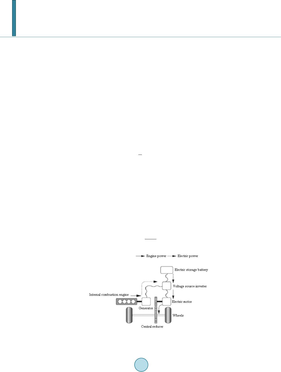 P.-M. Nicolae et al. 104 In this context the induction motor offers weight and efficiency advantages over the more conventional DC motors, besides its traditional advantages of robustness, low cost and well established manufacturing techniques. These motors have comparable torque and efficiency, along with a rugged, durable design. They don’t have a drag loss when the motor turns on and they don’t lose their efficiency during high speed or low torque condi- tions. This makes them well suited for hybrid electric vehicles. This work presents the design of a propulsion system for a series hybrid electric vehicle powered by an induc- tion motor. For the operation of the hybrid electric vehicle, electric storage batteries charged by solar batteries are used. The used block diagram of the hybrid electric vehicle is depicted in Figure 1 [12]. The parameters of the chosen hybrid electric vehicle are: • Rated power: Pn = 60 kW; • Range: L = 75 km; • Induction motor pole pairs: p1 = 1; • Vehicle speed: v = 75 km/h. 2. Sizing of the Electric Storage Batteries For the operation of the hybrid electric vehicle are used electric storage batteries charged by solar batteries [13]. Hybrid electric vehicle running time to a speed of 50 km/h and at a distance of 160 km is: 1 L th v = = (1) The energy required to operate the hybrid electric vehicle at a power of 8 kW and with a running time of 1 h is: 216 n EP tMJ= ⋅= (2) To have this energy it can be used electric accumulators. To do this, one chooses an accumulator that has a capacity C of 150 Ah: 4 150150 1150360054 10C AhAs== ⋅= ⋅=⋅ (3) The energy stored in the accumulator is: 4 648 10 AE ENUI tJ= ⋅⋅=⋅ (4) The number of electric accumulators is: 30 n AE AE E NEN = = (5) Figure 1. Structure and power flow diagram for a series hybrid electric vehicle. 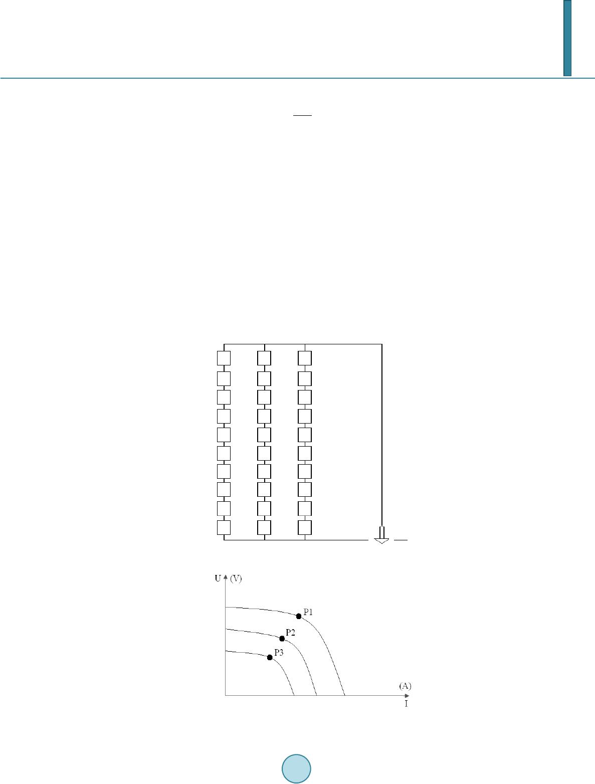 P.-M. Nicolae et al. 105 The energy of a battery is: 7.2 n AE AE E E MJ N = = . (6) The Ag-Zn electric storage batteries disposal is depicted in Figure 2 [14]. 3. Photoelectric System Sizing Charging of the electric storage batteries is made from a solar cells system. These batteries will not give the same energy throughout the day [15]. The surface of the solar battery for charging the electric storage batteries is S = 20 m2. For a system of fixed and mobile solar panels, the power can be calculated as: . PUIno hours η = ⋅⋅⋅ (7) For the fixed system the efficiency is η = 0.4 and for the mobile system η = 1. The coordinates of the operation points from the operation characteristic of the batteries (Figure 3) are calcu- lated as follows: 3 1 11 1 1 11 201 100.48000 100(100, 80) / 80 PW PU VP I PUA = ⋅⋅⋅= = ⇒ = = (8) Figure 2. Electric storage batteries disposal. Figure 3. The operation characteristic of the batteries.  P.-M. Nicolae et al. 106 3 2 22 2 2 22 200.8 100.46400 90(90, 71.11) / 71.11 PW PU VP I PUA =⋅⋅⋅= = ⇒ = = (9) 3 3 33 2 3 33 200.7 100.45600 80(80, 70) / 70 PW PU VP I PUA =⋅⋅⋅= = ⇒ = = (10) The energy given by the mobile system is: 123 80 1006360071.11 9023600708013600239E EEEMJ=++=⋅⋅⋅+ ⋅⋅⋅+⋅⋅⋅= (11) The energy of the fixed system is: 239 0.45107.55E MJ=⋅= (12) From these calculations it is observed that the mobile system provides more energy, because this system fol- lows the sun and provides the maximum energy in the range of given hours. 4. Aspects Concerning Induction Motor Designing The induction motor was designed considering the following rated data: • Rated power: Pn = 60 kW; • Rated voltage: Un = 230/400 V; • Speed: nN = 2985 rot/min; • Number of pole pairs: p1 = 1. Further in the paper, the most representative parameters and results yielded from the induction motor design- ing algorithm are exposed. The rated current is given by: 3 cos NN N UI P ϕη ⋅⋅ ⋅⋅= (13) where cosφ = 0.85 and η = 0.91. In this case IN = 112 A. Next, one determines the induction motor parameters. These are: the resistances R1 and R2, the inductances L1 and L2, the coupling inductance M, and the idling current I0 [16]. Determination of the internal resistance of the motor is calculated considering the power losses as: 12 0.13 () NN P RRI⋅=⋅+ ⋅ (14) It results that: R1 = R2 = 0.08 Ω. The idle current is given by: 00.3 33.6 N II A = ⋅= (15) The inductance is determined as: 01 N U LI ω =⋅ (1 6) where ω1 = 314 rad/s. In this case, L = 0.021 H. The coupling inductance is: 0.9ML= ⋅ (17) In our case M = 0.0189 H. Steady state equations of the induction motor are: 11 () dq qr URILI MI ω =⋅−⋅⋅+ ⋅ (18) 21 () qddr URILIMI ω =⋅+⋅⋅+ ⋅ (19) 1 0( )() drqr q RILI MI ωω =⋅− −⋅⋅+⋅ (2 0)  P.-M. Nicolae et al. 107 1 0( )() qrdr d RILI MI ωω =⋅+ −⋅⋅+⋅ (21) Control of the algorithm takes into account the electromagnetic torque function in the form: 1() elmgdr qdqr MpM IIII=⋅⋅ ⋅−⋅ (22) The maximum of the function is analyzed by considering the method of Lagrange multipliers. One imposes a maximum stator current: 22 22 16,307.2 dq N III A+= = (23) For the stator flux Ψs one imposing a value closes to the magnetic saturation (Ψs=1.3 Wb) [17]: 2 22 ()( ) sddrq qr LIMILI MIΨ=⋅+⋅+⋅+⋅ (24 ) For the induction motor starting, the voltages Ud and Uq are written as: 11 () ddq qr UR ILIMI ω =⋅−⋅⋅+ ⋅ (25) 11 () qq ddr UR ILIMI ω =⋅+⋅⋅+ ⋅ (26) and the following values are obtained: ω1 = 8.21 rad/s; Ud = 0.064 V; Uq = 9.626 V. Hybrid electric vehicle operation at rated speed is given by: 400 () 0( ) 0( )() 0( )() () (2/ 60)3 dqqr qd dr drNqrq qrNdrd Nq drdqr NN RILI MI RILIMI RILIMI RILIMI MMII II n ω ω ωω ωω ωπ =⋅−⋅ ⋅ +⋅ =⋅ +⋅⋅ +⋅ =⋅−− ⋅⋅+⋅ =⋅+− ⋅⋅+⋅ = ⋅⋅ −⋅ = ⋅⋅⋅ (27 ) and has the next results: Id = −31.409 A; Iq = 298.02 A; Iqr = −328.49 A; Idr = 32.253 A; MN = 13.331 Nm; ωN = 312.4 rad/s. The obtained voltages are: Ud = 15.17 V; Uq = 25.36 V. Regenerative braking of the hybrid electric vehicle is given by: 400 () 0( ) 0( )() 0( )() () dqqr qd dr drN qrq qrN drd Fq drdqr RILI MI RILIMI RILIMI RILIMI MMII II ω ω ωω ωω =⋅−⋅ ⋅ +⋅ =⋅ +⋅⋅ +⋅ =⋅−− ⋅⋅+⋅ =⋅+− ⋅⋅+⋅ = ⋅⋅ −⋅ (28) The obtained results are: 7.557 306.76 273.54 4.262 14.36 d q qr dr F IA IA IA IA M Nm = = − = = − = − (29) 5. Designing of the Voltage Source Inverter 5.1. Choosing the Power Electronics for the Converter The designing of the VSI was performed in a MATLAB module and is based on the following rated data: • Rotor AC line voltage: Uaclinerot = 400 V; 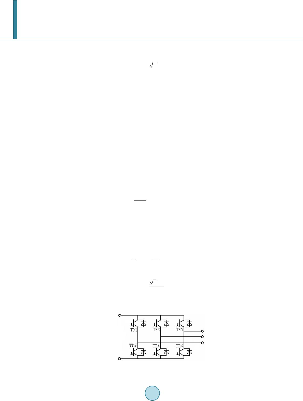 P.-M. Nicolae et al. 108 • Rotor rated current: Inrot = 112 A; • Fundamental frequency: f = 25 Hz; • Effective value of the rectified output voltage: Uef = 653.2 V; • Rated current amplitude for the rotor: 2 namrot nrot II= ⋅ = 158.4 A; • Rated average current: Imed = 0.9∙Imed = 100.8 A; • Ripple current, considering a peak of 5%: ILripple = 0.05∙Inamrot = 7.91 A. 5.2. Characteristic Parameters of the Voltage Source Inverter The designing method is used for a wide range of engines and voltages. The sizing of the voltage source inverter was made for a traction motor with the power of 60 kW and a voltage of 400 VAC. The maximum voltage that the voltage source inverter can supply for the motor is determined by the main supply voltage. Characteristic and functional parameters, from which the sizing of the voltage source inverter was performed, are the following: • Supplying voltage: Ua = 110 V (−30% ÷ +20%); • Input filter parameters: Cf = 1000 μF; Lf = 3.96 mH; • Operating frequency: fL = 2 kHz; • Induction motor rated current: In = 112 A. The simplified diagram of the inverter is depicted in Figure 4. 5.3. Calculation of the Conduction Time Full conduction time t1 is determined from the condition that the average voltage at the motor terminals not to exceed its rated voltage, respectively Un = 400 V. For the switching period 3 1/0.0005 10 L Tf s − = =⋅ and the supplying voltage Ua = 110 V, results: 3 1 0.0037 10 n a TU ts U − ⋅ = =⋅ (30) Changing of the voltage average value is achieved by changing the time length of the conduction, while maintaining a constant switching period (corresponding to an operating frequency of 2 kHz). 5.4. Calculation of the Average Current through the IGBT The average current through the static contactor is a fundamental criterion for choosing it. The average current value is computed by mediation instantaneous values corresponding to a period: 00 11 sin( ) 2 T med Tn IidtIt dt T π ωω π == ⋅ ∫∫ (31) The current through the IGBT Iigbt is obtained with: 2n igbt I I π ⋅ = (3 2 ) In this case, Iigbt = 38.98 A. Since the induction motor is 60 kW/480 V, then the maximum current of the motor Imax is given by: Figure 4. Voltage source inverter diagram.  P.-M. Nicolae et al. 109 max 1.5 n II= ⋅ . (3 3) In our case Imax = 129.90 A. The average value corresponding to the maximum motor current is: max 1 2 med I I π ⋅ = (34) In this case, Imed1 = 58.47 A. 5.5. Network Filter Sizing The network filter limits to a very large extent the switching surges and protects the equipment against net- work’s short duration voltage variations. Short-term variations of the voltage applied to the equipment are largely caused by instability of the galvanic connection between the sensors and the contact line [18]. Natural frequency of resonance (f0) for the filter is given by: 0 1 2 f fLC π =⋅⋅ (35) In this case, f0 = 79.97 Hz. In order to not fall into the spectrum fn of the harmonics produced by the inverter, f0 must be lower than the lowest operating frequency of the inverter, meaning f0 < fmin. Because fmin = f = 2 kHz and f0 = 79.97 Hz, the above condition is satisfied. 5.6. Choosing the Switching Transistors Depending on the parameters Imax and the rated voltage imposed, from the catalog of SEMIKRON manufacturer of electronic components was chosen the following IGBT model: SKM900GA12E4 (SEMITRANS), which sa- tisfies the conditions [19-20 ]: maxmax log 900 cata II A≤= (36) log 1200 a ncata UU V≤= (37) 5.7. Choosing and Verification of the Cooling System The dissipation of the heat that is generated in the semiconductor during conduction is made via an aluminum radiator that is cooled with forced air flow. Radiator sizing criteria is that the semiconductor junction tempera- ture does not exceed the limit specified by the manufacturer, namely 175 °C under long-term. The radiator is a subset of the equipment, with the aim of maintaining the temperature within limits for the proper functioning of the equipment, especially IGBT. The thermal effects of the electric current peak by conduction state represent the worst case during operation. Other important computed parameters are: • Switching losses of the transistor: ( ) 52.37 medT comTon offcom ccref I P EEfW I = +⋅⋅= (38) • Conduction losses of the transistor: 1 216.48 condTCEsat cmed t P UIW T =⋅⋅= (3 9) • Average current through the antiparallel diode: 2 /3 00 11 sin( ) 2 T med Tn IidtIt dt T π ωω π = =⋅ ∫∫ (40 )  P.-M. Nicolae et al. 110 23 60.42 4 n med I IA π ⋅⋅ = = (41) • Antiparallel diode switching losses: () 8.73 medD comDon offcom ccref I P EEfW I = +⋅⋅= (42) One used data catalog for voltage drops at saturation. The total average power generated inside the case by a module is: 257.92 TD PP PW=+= (43) Total losses on all three phases [21]: 3 737.77 phase PP W=⋅= ( 44) Was made the preliminary selection of the radiator type P16_300_16B, with the technical characteristics spe- cified in the catalog tab, cooled by an air flow produced by the fan type SK-Heat Sink P16_300_16B, with the technical characteristics specified in the catalog of the manufacturer. Junction over-temperature corresponding to the average power previously computed is checked within the chosen cooling conditions: 0j th TTT PR ∆= − =⋅ ∑ (45) The absolute temperature of the junction depends on the maximum ambient temperature specific to the tem- perate climate: T0 = 40˚C. The thermal resistances involved in this calculation are specified in the power transistor catalog, respectively the radiator catalog: • Thermal resistance junction—capsule for IGBT: RthjcT = 0.035 K/W; • Thermal resistance junction—capsule for diode: RthjcD = 0.041 K/W ; • Thermal resistance capsule—radiator: Rthcr = 0.038 K/W; • Thermal resistance of the radiator, at forced cooling with an air flow of 295 m3/h: Rthr= 0.031˚C /W. The average temperature of the junction is computed both for IGBT, and for antiparallel diode located in the same capsule. The general relation for calculating the junction temperature is: 0 () jthjc thcr thr TT PRRR= +⋅++ (46) Junction temperature for IGBT is obtained with: 0 ( )() 341.11 448.15 jTcomT condTthjcTthcrthr TTPPRR R KK =+ +⋅ ++ = < (47) In this case TjT = (341.11 – 273.15) = 67.96˚C. For the antiparallel diode, the junction temperature is computed with: 0 ( )() 320.12448.15 . jDcondD comDthjcDthcrthr TTPPRR R KK =++ ⋅ ++ = < (48) In this case: TjD = 320.12 – 273.15 = 46.97˚C. The results show that the cooling condition is fulfilled, namely: 175(448,15 ) j jad TTC orK≤=° ( 49)  P.-M. Nicolae et al. 111 Results a factor of safety in heating of 67.96/175 = 0.388, which shows that the sizing of cooling conditions has been rigorously made, without large reserves and so without undue consumption of materials and within a minimum possible size. For reliability an IGBT transistor was chosen with rated data higher than those considered to be adequate to the rated data of the induction motor. Evaluating the results obtained by the sizing methods is observed that an optimal configuration was used [22]. 6. Conclusions The paper was intended for a study on hybrid electric vehicle driving systems and on electric storage batteries they use. The advantages of the electric drive system with the induction motor and voltage source inverter re- vealed that it satisfies the requirements of the present application. The drive systems based on the induction mo- tor will eliminate the most disadvantages of DC drive systems. The results obtained from the designing algorithm of the induction motor show that an optimal configuration was used. In the paper was also presented a sizing algorithm for the power components of the voltage source inverter. Choosing of the power semiconductor devices was made from the data catalog of a producer of electronic com- ponents and the results obtained by computing were in good agreement with those from the catalog. One can conclude that is possible to design propulsion system for a hybrid electric vehicle with the given rated data for the specified application and the required performance. Given that the conventional means of transport (with internal combustion engine) are the main source of chemical and noise pollution on the planet, h ybrid electric transportation systems are a more viable alternative for transporting people and goods. References [1] EIA (2012) Short Term Energy Outlook March 2012. U.S. Energy Information Administration. [2] IEA (2010) World Energy Outlook 2010. International Energy Agency, Paris. [3] Klass, L.D. (1998) Biomass for Renewable Energy, Fuels and Chemicals. Elsevier Inc., Philadelphia. [4] BP (2011) BP Statistical Review of World Energy June 2011. [5] IEA (2011) Key World Energy Statistcs 2011. International Energy Agency, Paris. [6] Brown, S., Pyk ea , D. and Steenhof, P. (2010) Electric Vehicles: The Role and Importance of Standards in an Emerging Market. Energy Policy, 38, 3797-3806. http://dx.doi.org/10.1016/j.enpol.2010.02.059 [7] Woods, L.R. and Lawrance, K.L. (2013) U.S. Department of Energy—Energy Efficiency and Renewable Energy. http://www1.eere.energy.gov [8] Hori, Y. (2004) Future Vehicle Driven by Electricity and Control-Research on Four-Wheel-Motored UOT Electric March II. IEEE Transactions on Industrial Electronics, 51, 954-962. http://dx.doi.org/10.1109/TIE.2004.834944 [9] Chan, C. (2002) The State of the Art of Electric and Hybrid Electric. Proceedings of the IEEE, 90. [10] Naito, S., Mutoh, N., Takagi, T. and Kouchi, Y. (1995) AC Drive Systems for Electric Vehicles. Hitachi Review, 77. [11] Yamamura, H., Masa ki, R., Koizumi , O., Naoi, K. and Naito, S. (1992) Development of Powertrain System for Nissan FEV. Proceedings of the 11th Electric Vehicle Symposium, Florence. [12] Katrasnik, T. (2007) Hybridization of Powertrain and Downsizing of IC Engine—A Way to Reduce Fuel Consumption and Pollutant Emissions—Part 1. Energy Conversion and Management, 48, 1411-1423. http://dx.doi.org/10.1016/j.enconman.2006.12.004 [13] Clondescu, Gh. and Tomuta, O.D. (1977) Electric Ac cumulators, Maintenance and Repair (Acumulatoare Electrice, Intretinere si Reparare—In Romanian). Universitatea Tehnica de Constructii Bucuresti. [14] Corrigan, D., Menjak, I. and Dhar, S. (2000) Nickel -Metal Hydride Batteries for ZEV-Range Hybrid Electric Vehicle. PNGV Future Truck Technical Report, University of California. [15] Noreus, D. (2000) Substitution of Rechargeable NiCd Batteries, a Background Document to Evaluate the Possibilities of Finding Alternatives to NiCd Batteries. Arrhenius Laboratory, Stockholm University. [16] Câmpeanu, A., Vlad, I. and Enache, S. (2011) Aided Design of Electrical Machines (Proiectarea Asistata a Masinilor Electrice—In Romanian). Universitaria, Craiova. [17] Buja, G. , Casadei, D. and Serra, G. (1998) Direct Stator Flux and Torque Control of an Induction Motor: Theorethical  P.-M. Nicolae et al. 112 Analysis and Experimental Results. Conference of IEEE Industrial Electronics Society, IECON' 98, 50-64. [18] Choi, B. (2007) Analysis of Input Filter Interactions in Switching Power Converters. IEEE Transactions On Power Electronics, 22, 452-460. http://dx.doi.org/10.1109/TPEL.2006.889925 [19] http://www.semikron.com/ [20] http://www.semikron.com/products/data/cur/assets/SKM900GA12E4_22892130.pdf [21] Pou, J., Osorno, D., Zaragoza, J. , Ceballos, S. and Jaen, C. (2011) Power Losses Calculation Methodology to Evaluate Inverter Efficiency in Electrical Vehicles. Proceedings of the 7th International Conference opn Workshop Compatibil- ity and Power Electronics, CPE, Artic le No. 5942269, 404-409. [22] http://iota.ee.tuiasi.ro |