

Paper Menu >>
Journal Menu >>
 Journal of Modern Physics, 2011, 2, 131-135 doi:10.4236/jmp.2011.23020 Published Online March 2011 (http://www.SciRP.org/journal/jmp) Copyright © 2011 SciRes. JMP Electric Field and Hot Spots Formation on Divertor Plates Yuri Igitkhanov, Boris Bazylev Karlsruhe Institute of Technology, Association EURATOM-KIT, Karlsruhe, Germany E-mail: [email protected] Received January 18, 2011; revised February 24, 2011; accepted February 27, 2011 Abstract In this paper, we consider the intensive erosion of tungsten brush-type armour structures that face the plasma in divertor fusion reactors. Surface erosion caused by multiple transient events (ELMs, disruption, etc.) could lead to the formation of a corrugated wedge-type shape. Our analysis shows that the augmentation of surface roughness increases the electric field at the vicinity of the wedge-type tips, thus enabling the formation of electric arcs. Specifically, under reactor conditions, the breakdown of the sheath potential may trigger uni- polar arcs that will strongly contaminate the plasma with the resulting tungsten ions. We show that the ero- sion caused by arcs is almost two orders of magnitude larger than that caused by DT ion sputtering and comparable with that caused by self-sputtering. Keywords: Plasma Facing Components, Erosion, Unipolar Arcs, Dust Formation 1. Introduction The tungsten macro-brush (W-brush) structure has been envisaged as a plausible design for the divertor plates of ITER in order to mitigate surface cracking caused by energy loads of transient events [1]. Experimental and numerical investigations have already indicated that dis- ruptions and giant ELMs power loadings may result in melting, evaporation, and vapor-shield formation of W-brush structures under ITER conditions [2,3]. In addi- tion, it is known that the pressure gradient along the tar- get surface moves the molten layer and contributes to the surface roughness. Actually, for the proposed ITER ELMs size, it has been estimated that, after more than one thousand ELMs, the molten layer thickness is within the millimeter scale. During ITER operation, several hundred disruptions may occur and create a molten sur- face layer of depth of up to hundred microns per disrup- tion. This melting process has been investigated numeri- cally using the MEMOS code [4]. The calculation showed that ELMs are the main responsible for the tar- get’s erosion and thus determine the lifetime of the di- vertor plates. The cross-section of the model for the W-brush plate used in the present numerical simulations is shown in Figure 1. The typical sizes of the elements of the macro-brush amour vary within the following ranges: diameter of brushes, D ~ 0.5 - 1.0 cm; depth of the gaps between the brushes, h ~ 1 cm; width of the gap, a~0.5-1mm (see Figure 1). In order to avoid sharp corners, each brush element is supposed to be rounded with a radius R that varies from 0.5 to 1 mm. The surface roughness is nor- mally much less than 1 mm but it may reach 1 mm in the case of giant ELMs. Yet, as shown by earlier calculations, splashing of molten droplets does not occur because the capillary pressure exceeds the centrifugal pressure at the rounded surface corners, which constitutes the Taylor criterion limiting the outflowing of the molten layer [4]. However, we will show below that surface roughness can trigger unipolar arcs that would eject a substantial amount of tungsten atoms into the plasma. This mecha- nism may contaminate the plasma much more than plasma sputtering and evaporation. In Figure 2, we show the evolution of the corrugated surface under recurrent impact of ELM-pulses with a heat load of Q = 1.6 MJ/m2 and an exposition time t = 0.5 ms, as reported in [4]. The corrugated shape of the surface starts to form with the melting of the originally flat W-brush elements shown in Figure 1. The molten layer is then pushed to the left under the pressure of the incoming plasma. Since the molten material re-solidifies in between two ELMs, a peak starts to appear on the left edge of each brush ele- ment. As this mechanism repeats itself, the right edge of the brush element is shadowed by the corresponding peak of the neighboring brush element, thus protecting it from plasma exposure. This process eventually leads to 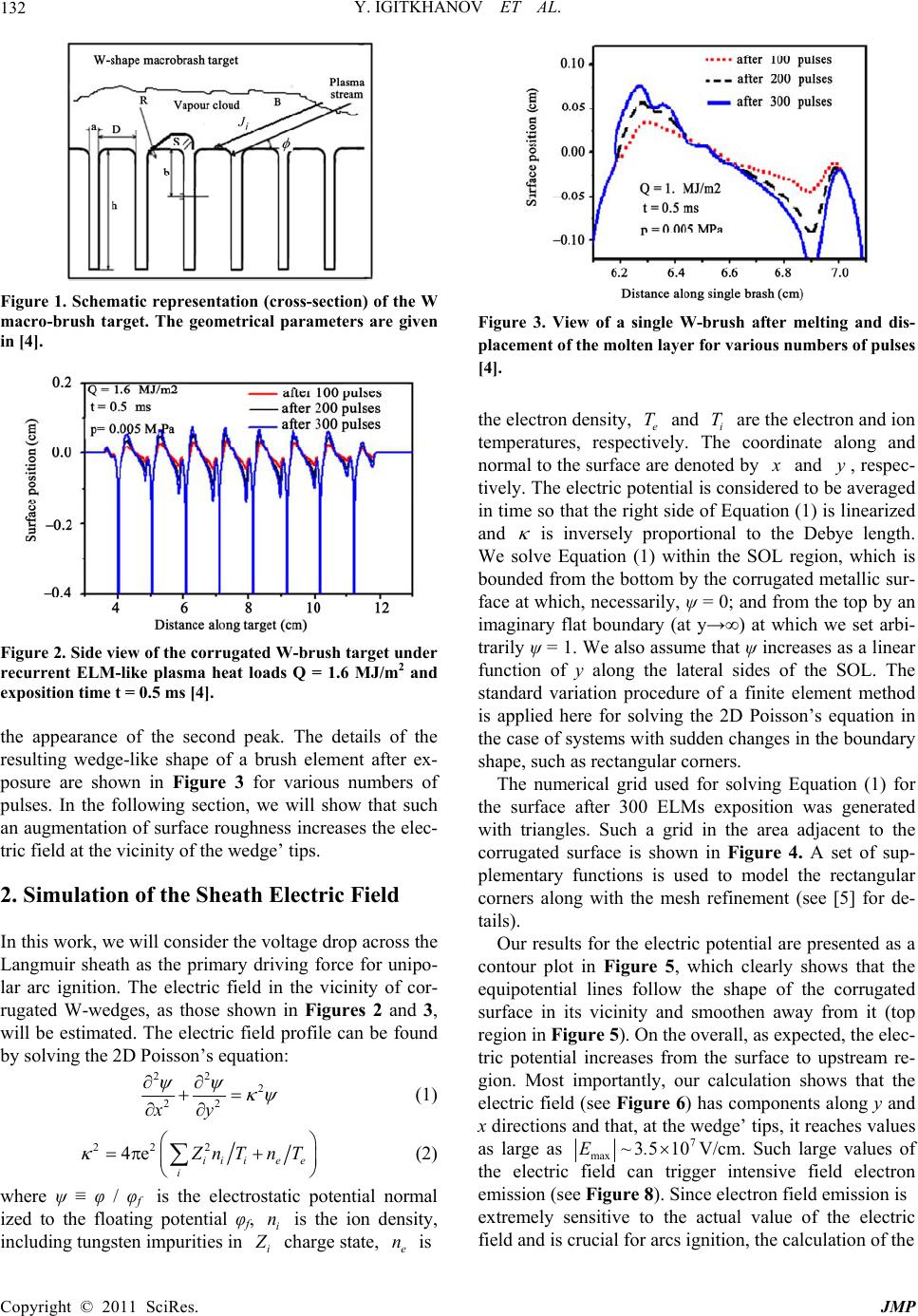 Y. IGITKHANOV ET AL. 132 Figure 1. Schematic representation (cross-section) of the W macro-brush target. The geometrical parameters are given in [4]. Figure 2. Side view of the corr ugated W-brush target under recurrent ELM-like plasma heat loads Q = 1.6 MJ/m2 and exposition time t = 0.5 ms [4]. the appearance of the second peak. The details of the resulting wedge-like shape of a brush element after ex- posure are shown in Figure 3 for various numbers of pulses. In the following section, we will show that such an augmentation of surface roughness increases the elec- tric field at the vicinity of the wedge’ tips. 2. Simulation of the Sheath Electric Field In this work, we will consider the voltage drop across the Langmuir sheath as the primary driving force for unipo- lar arc ignition. The electric field in the vicinity of cor- rugated W-wedges, as those shown in Figures 2 and 3, will be estimated. The electric field profile can be found by solving the 2D Poisson’s equation: 22 2 22 xy (1) 222 4e ii ie e i Z nT nT (2) where ψ ≡ φ / φf is the electrostatic potential normal ized to the floating potential φf, i is the ion density, including tungsten impurities in n i Z charge state, is e n Figure 3. View of a single W-brush after melting and dis- placement of the molten layer for various numbers of pulses [4]. the electron density, e and i are the electron and ion temperatures, respectively. The coordinate along and normal to the surface are denoted by T T x and , respec- tively. The electric potential is considered to be averaged in time so that the right side of Equation (1) is linearized and y is inversely proportional to the Debye length. We solve Equation (1) within the SOL region, which is bounded from the bottom by the corrugated metallic sur- face at which, necessarily, ψ = 0; and from the top by an imaginary flat boundary (at y→∞) at which we set arbi- trarily ψ = 1. We also assume that ψ increases as a linear function of y along the lateral sides of the SOL. The standard variation procedure of a finite element method is applied here for solving the 2D Poisson’s equation in the case of systems with sudden changes in the boundary shape, such as rectangular corners. The numerical grid used for solving Equation (1) for the surface after 300 ELMs exposition was generated with triangles. Such a grid in the area adjacent to the corrugated surface is shown in Figure 4. A set of sup- plementary functions is used to model the rectangular corners along with the mesh refinement (see [5] for de- tails). Our results for the electric potential are presented as a contour plot in Figure 5, which clearly shows that the equipotential lines follow the shape of the corrugated surface in its vicinity and smoothen away from it (top region in Figure 5). On the overall, as expected, the elec- tric potential increases from the surface to upstream re- gion. Most importantly, our calculation shows that the electric field (see Figure 6) has components along y and x directions and that, at the wedge’ tips, it reaches values as large as 7 max 35 10E~.V/cm. Such large values of the electric field can trigger intensive field electron emission (see Figure 8). Since electron field emission is extremely sensitive to the actual value of the electric field and is crucial for arcs ignition, the calculation of the Copyright © 2011 SciRes. JMP 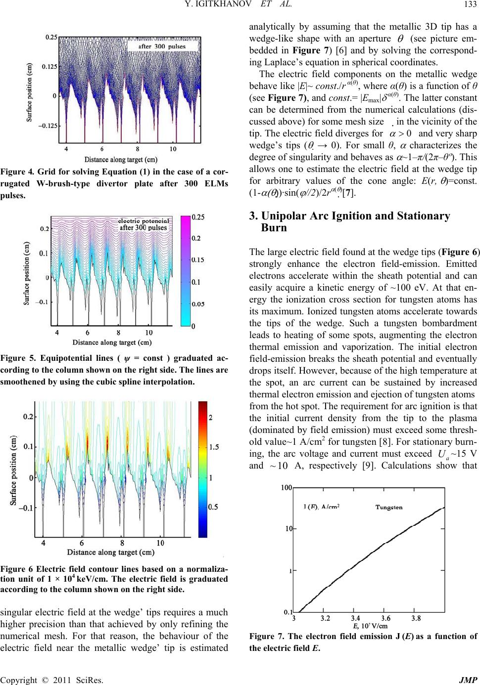 Y. IGITKHANOV ET AL.133 Figure 4. Grid for solving Equation (1) in the case of a cor- rugated W-brush-type divertor plate after 300 ELMs pulses. Figure 5. Equipotential lines ( ψ = const ) graduated ac- cording to the column shown on the right side. The lines are smoothened by using the cubic spline interpolation. Figure 6 Electric field contour lines based on a normaliza- tion unit of 1 × 10⁴ keV/cm. The electric field is graduated according to the column shown on the right side. singular electric field at the wedge’ tips requires a much higher precision than that achieved by only refining the numerical mesh. For that reason, the behaviour of the electric field near the metallic wedge’ tip is estimated analytically by assuming that the metallic 3D tip has a wedge-like shape with an aperture (see picture em- bedded in Figure 7) [6] and by solving the correspond- ing Laplace’s equation in spherical coordinates. The electric field components on the metallic wedge behave like |E|~ const./r α(θ), where α(θ) is a function of θ (see Figure 7), and const.= |Emax| α(θ). The latter constant can be determined from the numerical calculations (dis- cussed above) for some mesh size in the vicinity of the tip. The electric field diverges for 0 and very sharp wedge’s tips ( → 0). For small θ, characterizes the degree of singularity and behaves as ~1–π/(2π–θº). This allows one to estimate the electric field at the wedge tip for arbitrary values of the cone angle: E(r, )=const. (1- )·sin( //2)/2r [7]. 3. Unipolar Arc Ignition and Stationary Burn The large electric field found at the wedge tips (Figure 6) strongly enhance the electron field-emission. Emitted electrons accelerate within the sheath potential and can easily acquire a kinetic energy of ~100 eV. At that en- ergy the ionization cross section for tungsten atoms has its maximum. Ionized tungsten atoms accelerate towards the tips of the wedge. Such a tungsten bombardment leads to heating of some spots, augmenting the electron thermal emission and vaporization. The initial electron field-emission breaks the sheath potential and eventually drops itself. However, because of the high temperature at the spot, an arc current can be sustained by increased thermal electron emission and ejection of tungsten atoms from the hot spot. The requirement for arc ignition is that the initial current density from the tip to the plasma (dominated by field emission) must exceed some thresh- old value~1 A/cm2 for tungsten [8]. For stationary burn- ing, the arc voltage and current must exceed a~15 V and A, respectively [9]. Calculations show that U 10~ Figure 7. The electron field emission J (E) as a function of the electric field E. Copyright © 2011 SciRes. JMP 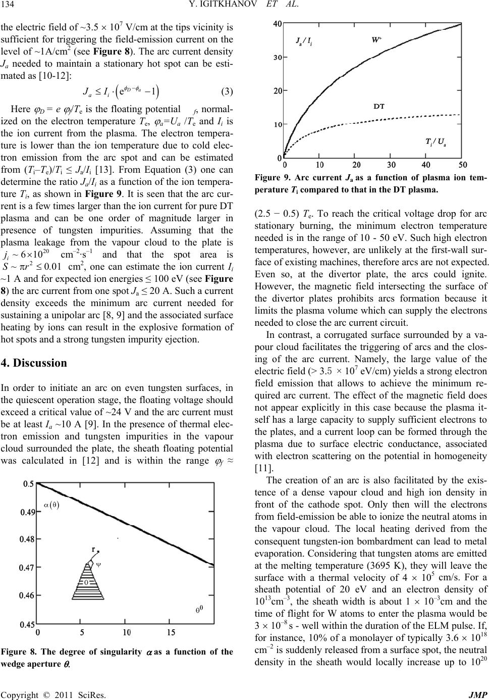 Y. IGITKHANOV ET AL. 134 1 the electric field of ~3.5 107 V/cm at the tips vicinity is sufficient for triggering the field-emission current on the level of ~1A/cm2 (see Figure 8). The arc current density Ja needed to maintain a stationary hot spot can be esti- mated as [10-12]: e Da ai JI (3) Here D = e f/Te is the floating potential f, normal- ized on the electron temperature Te, a=Ua /Te and Ii is the ion current from the plasma. The electron tempera- ture is lower than the ion temperature due to cold elec- tron emission from the arc spot and can be estimated from (Ti–Te)/Ti ≤ Ja/Ii [13]. From Equation (3) one can determine the ratio Ja/Ii as a function of the ion tempera- ture Ti, as shown in Figure 9. It is seen that the arc cur- rent is a few times larger than the ion current for pure DT plasma and can be one order of magnitude larger in presence of tungsten impurities. Assuming that the plasma leakage from the vapour cloud to the plate is cm–2·s–1 and that the spot area is cm2, one can estimate the ion current Ii ~1 A and for expected ion energies ≤ 100 eV (see Figure 8) the arc current from one spot Ja ≤ 20 A. Such a current density exceeds the minimum arc current needed for sustaining a unipolar arc [8, 9] and the associated surface heating by ions can result in the explosive formation of hot spots and a strong tungsten impurity ejection. 20 610 i j~ 200S~ r. 1 4. Discussion In order to initiate an arc on even tungsten surfaces, in the quiescent operation stage, the floating voltage should exceed a critical value of ~24 V and the arc current must be at least Ia ~10 A [9]. In the presence of thermal elec- tron emission and tungsten impurities in the vapour cloud surrounded the plate, the sheath floating potential was calculated in [12] and is within the range f ≈ Figure 8. The degree of singularity as a function of the wedge aperture Figure 9. Arc current Ja as a function of plasma ion tem- perature Ti compared to that in the DT plasma. (2.5 − 0.5) Te. To reach the critical voltage drop for arc stationary burning, the minimum electron temperature needed is in the range of 10 - 50 eV. Such high electron temperatures, however, are unlikely at the first-wall sur- face of existing machines, therefore arcs are not expected. Even so, at the divertor plate, the arcs could ignite. However, the magnetic field intersecting the surface of the divertor plates prohibits arcs formation because it limits the plasma volume which can supply the electrons needed to close the arc current circuit. In contrast, a corrugated surface surrounded by a va- pour cloud facilitates the triggering of arcs and the clos- ing of the arc current. Namely, the large value of the electric field (> 3.5 × 10⁷ eV/cm) yields a strong electron field emission that allows to achieve the minimum re- quired arc current. The effect of the magnetic field does not appear explicitly in this case because the plasma it- self has a large capacity to supply sufficient electrons to the plates, and a current loop can be formed through the plasma due to surface electric conductance, associated with electron scattering on the potential in homogeneity [11]. The creation of an arc is also facilitated by the exis- tence of a dense vapour cloud and high ion density in front of the cathode spot. Only then will the electrons from field-emission be able to ionize the neutral atoms in the vapour cloud. The local heating derived from the consequent tungsten-ion bombardment can lead to metal evaporation. Considering that tungsten atoms are emitted at the melting temperature (3695 K), they will leave the surface with a thermal velocity of 4 105 cm/s. For a sheath potential of 20 eV and an electron density of 1013cm–3, the sheath width is about 1 10–3cm and the time of flight for W atoms to enter the plasma would be 3 10–8 s - well within the duration of the ELM pulse. If, for instance, 10% of a monolayer of typically 3.6 1018 cm–2 is suddenly released from a surface spot, the neutral density in the sheath would locally increase up to 1020 Copyright © 2011 SciRes. JMP  Y. IGITKHANOV ET AL. Copyright © 2011 SciRes. JMP 135 cm–3. Assuming an ionization cross section of 210–16 cm2, a small fraction of the neutral atoms (10–3) would be ionized within the sheath, i.e., iw1017cm–3. This would effectively increase the existing plasma density near the target. For this example, a W+ ion produced in the sheath would need about several nanoseconds to fall back onto the surface. n~ Arcs erosion of tungsten according to vacuum data [9] is 0.62 10–4 g/coulomb and is proportional to the cur- rent flowing through the plate. Since the electron current forms a considerable part of the whole arc current, about 0.62 10–4 20 A = 1.2 mg per second of tungsten ma- terial will be released into plasma from one spot. Arcs are triggered at each tip and one arc occurs from 1cm2 wedge surface (Figure 1), therefore, the contamination rate from the all divertor plates (~100 m2 in ITER) may reach the level of 12 grams of tungsten per second or ~ 4 1022 tungsten impurity ions per second. 5. Conclusions In this paper, we have demonstrated that repetitive ELM events in ITER discharges increase the probability of arcing on corrugated wedge-shape armour surfaces. Al- though tungsten is a refractory material and the probabil- ity of arcing is low in quiescent plasma, in the case of transients, unipolar arcs can ignite and strongly contrib- ute to the erosion of the armour by ejecting tungsten im- purities (neutral vapor, molten and solid droplets) into the plasma. Moreover, arcs at the wedge’s tips may grow and eventually create hot spots. These have dominant thermal or burst-type emission that also releases a sub- stantial amount of tungsten impurities into the plasma. It is shown that the geometric enhancement of the electric field on the corrugated surface facilitates the arc triggering. We find that the electric filed at the wedges’ tips reaches a value sufficient to originate intensive field electron emission. The tungsten arc erosion rate per each spot is estimated as 1.2 mg per second. We note that since sputtering of the tungsten armour by DT ions is ~ 10-2 tungsten atoms per incident DT ion (for energies ≤100eV), the arc erosion according to Figure 9 is almost two orders of magnitude larger than that of sputtering yield, and comparable with self-sputtering yield. 6. Acknowledgments This work, supported by the European Communities un- der the contract of Association between EURATOM and Karlsruhe Institute of Technology, EURATOM and CCFE, was carried out within the framework of the European Fusion Development Agreement. The views and opinions expressed herein do not necessarily reflect those of the European Commission 7. References [1] A. Loarte, G. Saibene, R. Sartori, et al., "Transient Heat Loads in Current Fusion Experiments, Extrapolation to Iter and Consequences for its Operation,” Physica Scripta, Vol. 128, 2007, pp. 222-228. doi:10.1088/0031-8949/2007/T128/043 [2] B. Bazylev, G. Janeschitz, I. Landman et al., “ITER Transient Consequences for Material Damage: Modelling Versus Experiments,” Physica Scripta, Vol. T128, 2007, pp. 229-233. doi:10.1088/0031-8949/2007/T128/044 [3] A. Zhitlukhin, N. Klimov, I. Landman et al., “Effect of ELMS on ITER Armour Materials,” Journal of Nuclear Materials, Vol. 363-365, 2007, pp. 301-307. doi:10.1016/j.jnucmat.2007.01.027 [4] B. Bazylev, G. Janeschitz, I. Landman and S. Pestchanyi, “Erosion of Tungsten Armor after Multiple Intense Tran- sient Events in ITER,” Journal of Nuclear Materials, Vol. 337-339, 2005, pp.766-770. doi:10.1016/j.jnucmat.2004.10.070 [5] L. Olson, G. Georgiou and W. Schultz, “An Efficient Finite Element Method for Treating Singularities in Laplace’s Equation,” Journal of Computational Physics, Vol. 96, No. 2, 1991, pp.391-410. doi:10.1016/0021-9991(91)90242-D [6] S. Marchetti and T. Rozzi, “Electric Field Behavior near Metallic Wedges,” IEEE Transactions on Antennas and Propagation, Vol. 38,No. 9, 1990, pp.1333-1339. doi:10.1109/8.56983 [7] L. Landau, E. Lifshitz and L. Pitaevskii, “Electrodynam- ics of Continuous Media,” Vol. 8, 1984 (1rst Ed.), But- ter-Worth-Heinemann, ISBN 978-0-750-62634-7. [8] V. Granovski, “The Electric Current in a Gases,” (in Rus- sian), Nauka, Moscow, 1971. [9] J. Wesson, “Tokamaks,” 3rd edition, Oxford, 2004. [10] G. Hobs and J. Wesson, “Heat Flow through a Langmuir Sheath in the Presence of Electron Emission,” Plasma Physics, Vol. 9, 1967, pp. 85-87. doi:10.1088/0032-1028/9/1/410 [11] Yu. Igitkhanov, “On the Mechanism of Stationary Burn of Unipolar Micro-Arcs in the Scrape-Off Tokamak Plasma,” Contribution in Plasma Physics, Vol. 28, No. 4-5, 1988, pp. 421-425. doi:10.1002/ctpp.2150280425 [12] Yu. Igitkhanov and D Naujoks, “Sheath Potential Drop in the Presence of Impurities,” Contribution in Plasma Physics, Vol. 36 S, 1996, pp. 67-72. [13] A. Nedospasov and V. Petrov, “Model of the Unipolar Arc on a Tokamak Wall,” Journal of Nuclear Material, Vol. 76 & 77, 1978, pp. 490-491. |