

Paper Menu >>
Journal Menu >>
 Vol.3, No.3, 193-198 (2011) Natural Science http://dx.doi.org/10.4236/ns.2011.33025 Copyright © 2011 SciRes. OPEN ACCESS Retrieval of the ground surface reflectance along coast zone and island with MODIS image* Jinji Ma#, Xiaofan Li College of Physics and Electronic Information, Anhui Normal University, Wuhu, China; #Corresponding Author: [email protected] Received 26 December 2010; revised 27 January 2011; accepted 29 January 2011. ABSTRACT A new method based on lookup tables (LUTs) for retrieval of the ground surface reflectance along coastal zones and islands with MODIS (Moderate-resolution imaging spectroradiome- ter) image was described. Through simulation of the AHMAD radiative transfer model, we can retrieve the aerosol optical character with water pixels of MODIS image. Postulating the back- ground is cloudless and the atmosphere on the water is the same as that on the island, we can use the 6S radiative transfer model to compute the LUT about the ground surface reflectance, then use the interpolate method to get the re- flectance of the ground surface along coastal zones and islands through the reflectance of the land pixels of MODIS image, the geometric condition and the aerosol optical thickness. The LUT method is applied to determine the ground surface reflectance in Xiamen’s zone from the MODIS image. At last, the results were analyzed and its expectation errors were reported. Keywords: MODIS Image; Reflectance; Optical Thickness; Aerosol; Remote Sensing 1. INTRODUCTION How to get the ground surface reflectance is the key technology for remote sensing because it is important to use the image of satellite to retrieve ration and the ground information. Because the image of satellite in- cludes not only the ground information but also the at- mosphere information, so we must correct the errors from the atmosphere effect to the image. There are many kinds of methods for correcting error, but the most valid method is the direct correction from the image of satel- lite. In the beginning, people wanted to evade atmos- phere correction [1] through calculating the Normalized Difference Vegetation Index (NDVI) and synthesizing the DVI by the biggest value of the row of time [2]. Now, we mainly adopt the radiative transfer measurement ac- cording as atmospheric parameter to correct atmosphere [3]. For example, we usually use the dark object method [4] and the dark object subtraction method [5] to retrieve the optical character of the aerosol. The aim of these methods is to minimize the error due to the retrieval of the ground surface reflectance. Since the ocean surface is simpler than the land sur- face, and the atmospheric signal is almost 90% of the apparent reflectance over the ocean [6], so we think the atmospheric optical character cannot be significantly changed by the variation of ocean surface reflectance. Based on this property, and using the AHMAD radiative transfer model [7], we determine the aerosol optical character over the ocean through water pixels of MODIS image based on the LUT method [8]. If we think the atmospheric condition over the ocean is the same as that on the ground under cloudless condition, we can deter- mine the aerosol optical character, using the 6S model [9] on computing of the LUT about the ground surface re- flectance. Using the interpolation method to retrieve of the ground surface reflectance along coastal zones and islands with the LUT, aerosol optical character can be determined from the MODIS image. 2. METHOD 2.1. Retrieval of the Aerosol Optical Character from Pixel of MODIS Image There are different methods to retrieve of the aerosol optical character on the land and over the ocean from pixel of MODIS image. The aerosol optical character on the land is retrieved based on the dark method, and the aerosol optical character over the ocean is retrieved based on the LUT method. *National Natural Science Foundation, No. 40701132; Anhui Provincial N atural Science Founda t ion, No.070412042. 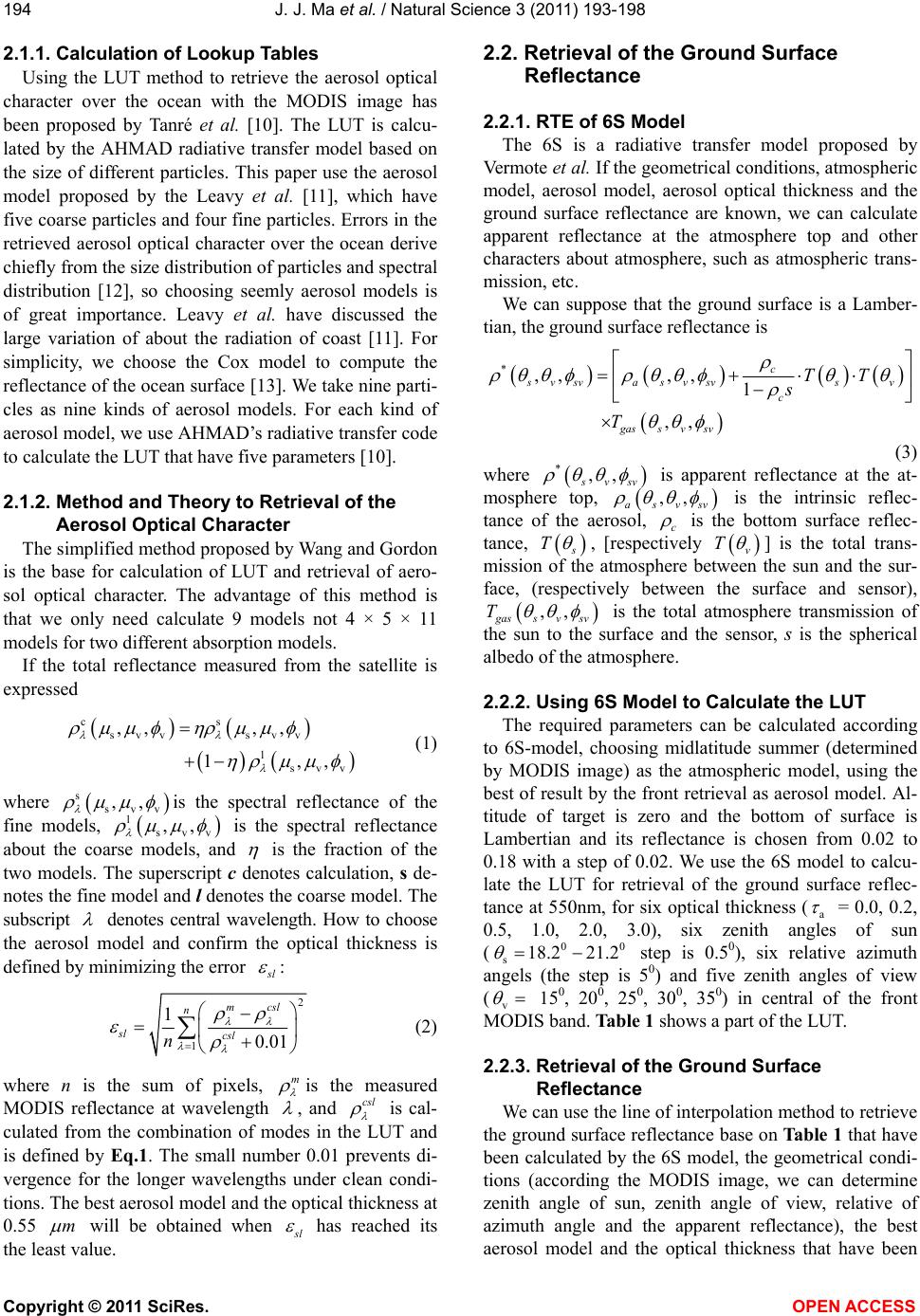 J. J. Ma et al. / Natural Science 3 (2011) 193-198 Copyright © 2011 SciRes. OPEN ACCESS 194 2.1.1. Calculation of Lookup Tables Using the LUT method to retrieve the aerosol optical character over the ocean with the MODIS image has been proposed by Tanré et al. [10]. The LUT is calcu- lated by the AHMAD radiative transfer model based on the size of different particles. This paper use the aerosol model proposed by the Leavy et al. [11], which have five coarse particles and four fine particles. Errors in the retrieved aerosol optical character over the ocean derive chiefly from the size distribution of particles and spectral distribution [12], so choosing seemly aerosol models is of great importance. Leavy et al. have discussed the large variation of about the radiation of coast [11]. For simplicity, we choose the Cox model to compute the reflectance of the ocean surface [13]. We take nine parti- cles as nine kinds of aerosol models. For each kind of aerosol model, we use AHMAD’s radiative transfer code to calculate the LUT that have five parameters [10]. 2.1.2. Method and Theory to Retrieval of the Aerosol Optical Character The simplified method proposed by Wang and Gordon is the base for calculation of LUT and retrieval of aero- sol optical character. The advantage of this method is that we only need calculate 9 models not 4 × 5 × 11 models for two different absorption models. If the total reflectance measured from the satellite is expressed cs svv svv l svv ,, ,, 1,, (1) where s svv ,, is the spectral reflectance of the fine models, l svv ,, is the spectral reflectance about the coarse models, and is the fraction of the two models. The superscript c denotes calculation, s de- notes the fine model and l denotes the coarse model. The subscript denotes central wavelength. How to choose the aerosol model and confirm the optical thickness is defined by minimizing the error s l : 2 1 1 0.01 mcsl n sl csl n (2) where n is the sum of pixels, m is the measured MODIS reflectance at wavelength , and csl is cal- culated from the combination of modes in the LUT and is defined by Eq.1. The small number 0.01 prevents di- vergence for the longer wavelengths under clean condi- tions. The best aerosol model and the optical thickness at 0.55 m will be obtained when s l has reached its the least value. 2.2. Retrieval of the Ground Surface Reflectance 2.2.1. RTE of 6S Model The 6S is a radiative transfer model proposed by Ver mo te et al. If the geometrical conditions, atmospheric model, aerosol model, aerosol optical thickness and the ground surface reflectance are known, we can calculate apparent reflectance at the atmosphere top and other characters about atmosphere, such as atmospheric trans- mission, etc. We can suppose that the ground surface is a Lamber- tian, the ground surface reflectance is *,,,, 1 ,, c svsva svsvsv c gass v sv TT s T (3) where *,, s vsv is apparent reflectance at the at- mosphere top, ,, asvsv is the intrinsic reflec- tance of the aerosol, c is the bottom surface reflec- tance, s T , [respectively v T ] is the total trans- mission of the atmosphere between the sun and the sur- face, (respectively between the surface and sensor), ,, g ass v sv T is the total atmosphere transmission of the sun to the surface and the sensor, s is the spherical albedo of the atmosphere. 2.2.2. Using 6S Model to Calculate the LUT The required parameters can be calculated according to 6S-model, choosing midlatitude summer (determined by MODIS image) as the atmospheric model, using the best of result by the front retrieval as aerosol model. Al- titude of target is zero and the bottom of surface is Lambertian and its reflectance is chosen from 0.02 to 0.18 with a step of 0.02. We use the 6S model to calcu- late the LUT for retrieval of the ground surface reflec- tance at 550nm, for six optical thickness (a = 0.0, 0.2, 0.5, 1.0, 2.0, 3.0), six zenith angles of sun (00 s18.2 21.2 step is 0.50), six relative azimuth angels (the step is 50) and five zenith angles of view (v 150, 200, 250, 300, 350) in central of the front MODIS band. Table 1 shows a part of the LUT. 2.2.3. Retrieval of the Ground Surface Reflectance We can use the line of interpolation method to retrieve the ground surface reflectance base on Table 1 that have been calculated by the 6S model, the geometrical condi- tions (according the MODIS image, we can determine zenith angle of sun, zenith angle of view, relative of azimuth angle and the apparent reflectance), the best aerosol model and the optical thickness that have been 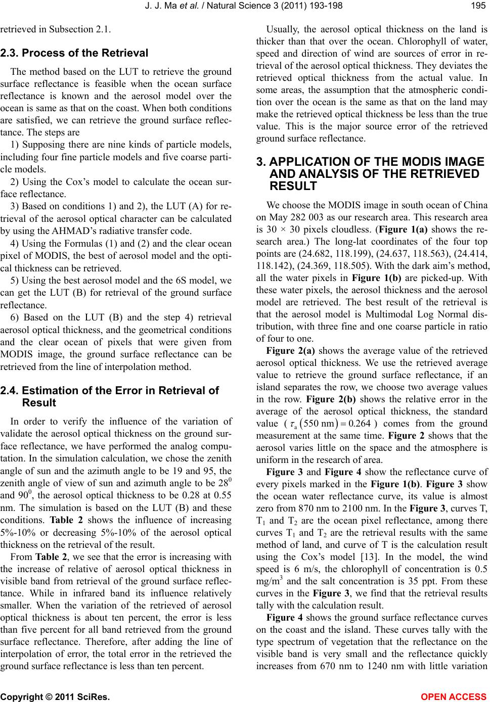 J. J. Ma et al. / Natural Science 3 (2011) 193-198 Copyright © 2011 SciRes. OPEN ACCESS 195195 retrieved in Subsection 2.1. 2.3. Process of the Retrieval The method based on the LUT to retrieve the ground surface reflectance is feasible when the ocean surface reflectance is known and the aerosol model over the ocean is same as that on the coast. When both conditions are satisfied, we can retrieve the ground surface reflec- tance. The steps are 1) Supposing there are nine kinds of particle models, including four fine particle models and five coarse parti- cle models. 2) Using the Cox’s model to calculate the ocean sur- face reflectance. 3) Based on conditions 1) and 2), the LUT (A) for re- trieval of the aerosol optical character can be calculated by using the AHMAD’s radiative transfer code. 4) Using the Formulas (1) and (2) and the clear ocean pixel of MODIS, the best of aerosol model and the opti- cal thickness can be retrieved. 5) Using the best aerosol model and the 6S model, we can get the LUT (B) for retrieval of the ground surface reflectance. 6) Based on the LUT (B) and the step 4) retrieval aerosol optical thickness, and the geometrical conditions and the clear ocean of pixels that were given from MODIS image, the ground surface reflectance can be retrieved from the line of interpolation method. 2.4. Estimation of the Error in Retrieval of Result In order to verify the influence of the variation of validate the aerosol optical thickness on the ground sur- face reflectance, we have performed the analog compu- tation. In the simulation calculation, we chose the zenith angle of sun and the azimuth angle to be 19 and 95, the zenith angle of view of sun and azimuth angle to be 280 and 900, the aerosol optical thickness to be 0.28 at 0.55 nm. The simulation is based on the LUT (B) and these conditions. Table 2 shows the influence of increasing 5%-10% or decreasing 5%-10% of the aerosol optical thickness on the retrieval of the result. From Table 2, we see that the error is increasing with the increase of relative of aerosol optical thickness in visible band from retrieval of the ground surface reflec- tance. While in infrared band its influence relatively smaller. When the variation of the retrieved of aerosol optical thickness is about ten percent, the error is less than five percent for all band retrieved from the ground surface reflectance. Therefore, after adding the line of interpolation of error, the total error in the retrieved the ground surface reflectance is less than ten percent. Usually, the aerosol optical thickness on the land is thicker than that over the ocean. Chlorophyll of water, speed and direction of wind are sources of error in re- trieval of the aerosol optical thickness. They deviates the retrieved optical thickness from the actual value. In some areas, the assumption that the atmospheric condi- tion over the ocean is the same as that on the land may make the retrieved optical thickness be less than the true value. This is the major source error of the retrieved ground surface reflectance. 3. APPLICATION OF THE MODIS IMAGE AND ANALYSIS OF THE RETRIEVED RESULT We choose the MODIS image in south ocean of China on May 282 003 as our research area. This research area is 30 × 30 pixels cloudless. (Figure 1(a) shows the re- search area.) The long-lat coordinates of the four top points are (24.682, 118.199), (24.637, 118.563), (24.414, 118.142), (24.369, 118.505). With the dark aim’s method, all the water pixels in Figure 1(b) are picked-up. With these water pixels, the aerosol thickness and the aerosol model are retrieved. The best result of the retrieval is that the aerosol model is Multimodal Log Normal dis- tribution, with three fine and one coarse particle in ratio of four to one. Figure 2(a) shows the average value of the retrieved aerosol optical thickness. We use the retrieved average value to retrieve the ground surface reflectance, if an island separates the row, we choose two average values in the row. Figure 2(b) shows the relative error in the average of the aerosol optical thickness, the standard value ( a550 nm0.264 ) comes from the ground measurement at the same time. Figure 2 shows that the aerosol varies little on the space and the atmosphere is uniform in the research of area. Figure 3 and Figure 4 show the reflectance curve of every pixels marked in the Figure 1(b). Figure 3 show the ocean water reflectance curve, its value is almost zero from 870 nm to 2100 nm. In the Figure 3, curves T, T1 and T2 are the ocean pixel reflectance, among there curves T1 and T2 are the retrieval results with the same method of land, and curve of T is the calculation result using the Cox’s model [13]. In the model, the wind speed is 6 m/s, the chlorophyll of concentration is 0.5 mg/ m3 and the salt concentration is 35 ppt. From these curves in the Figure 3, we find that the retrieval results tally with the calculation result. Figure 4 shows the ground surface reflectance curves on the coast and the island. These curves tally with the type spectrum of vegetation that the reflectance on the visible band is very small and the reflectance quickly increases from 670 nm to 1240 nm with little variation 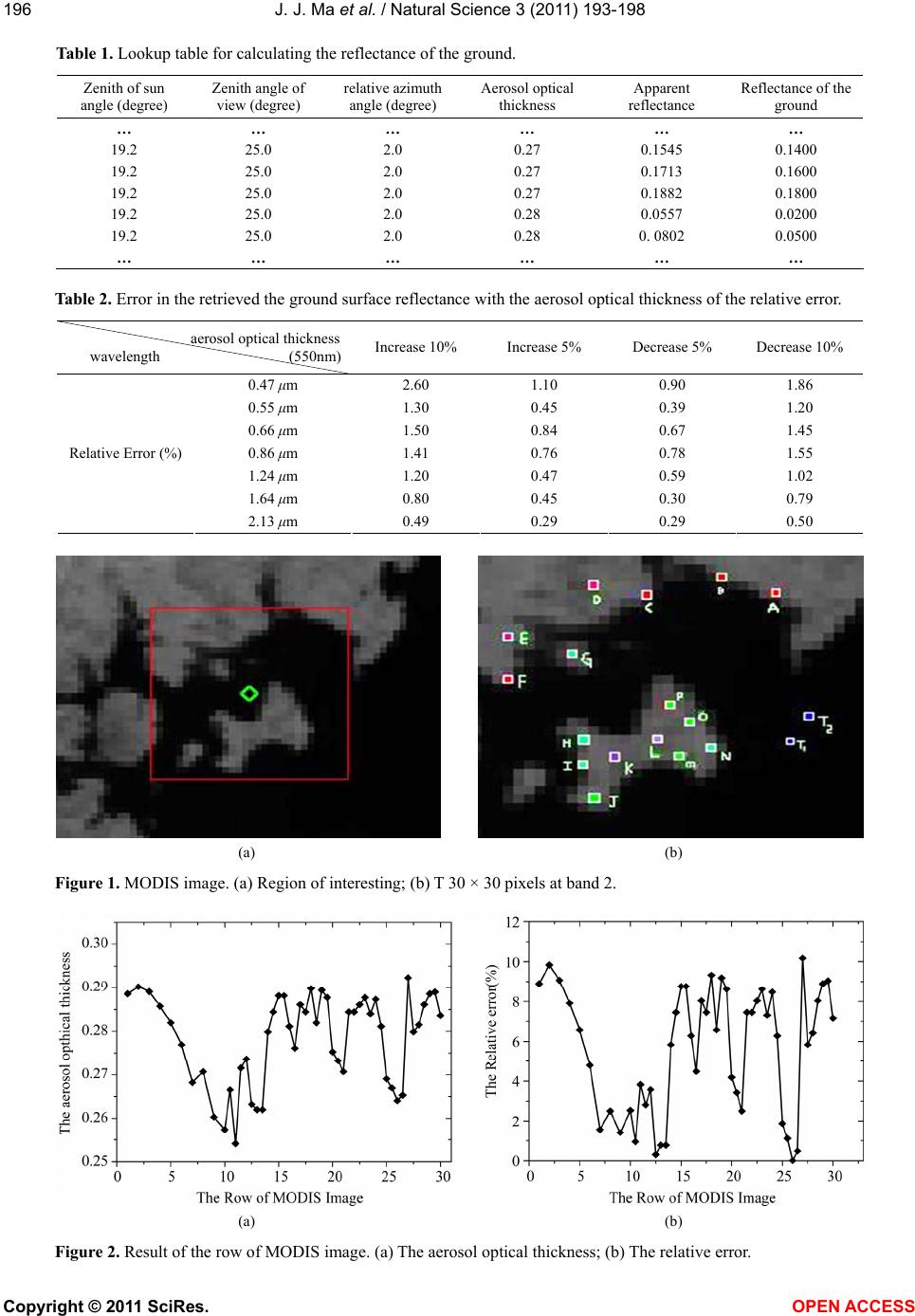 J. J. Ma et al. / Natural Science 3 (2011) 193-198 Copyright © 2011 SciRes. OPEN ACCESS 196 Table 1. Lookup table for calculating the reflectance of the ground. Zenith of sun angle (degree) Zenith angle of view (degree) relative azimuth angle (degree) Aerosol optical thickness Apparent reflectance Reflectance of the ground … … … … … … 19.2 25.0 2.0 0.27 0.1545 0.1400 19.2 25.0 2.0 0.27 0.1713 0.1600 19.2 25.0 2.0 0.27 0.1882 0.1800 19.2 25.0 2.0 0.28 0.0557 0.0200 19.2 25.0 2.0 0.28 0. 0802 0.0500 … … … … … … Table 2. Error in the retrieved the ground surface reflectance with the aerosol optical thickness of the relative error. aerosol optical thickness wavelength (550nm) Increase 10% Increase 5% Decrease 5% Decrease 10% 0.47 μm 2.60 1.10 0.90 1.86 0.55 μm 1.30 0.45 0.39 1.20 0.66 μm 1.50 0.84 0.67 1.45 0.86 μm 1.41 0.76 0.78 1.55 1.24 μm 1.20 0.47 0.59 1.02 1.64 μm 0.80 0.45 0.30 0.79 Relative Error (%) 2.13 μm 0.49 0.29 0.29 0.50 (a) (b) Figure 1. MODIS image. (a) Region of interesting; (b) T 30 × 30 pixels at band 2. (a) (b) Figure 2. Result of the row of MODIS image. (a) The aerosol optical thickness; (b) The relative error. 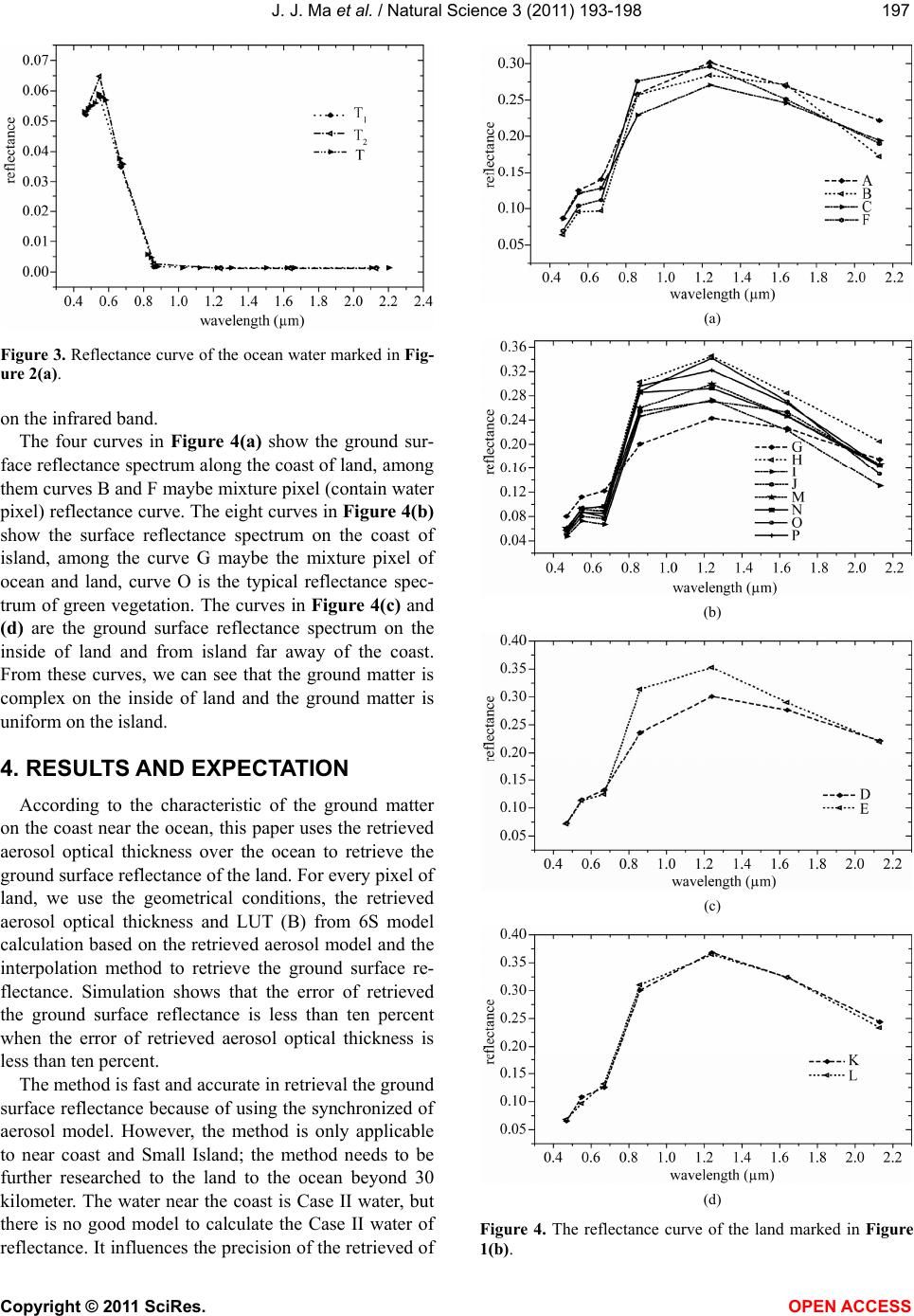 J. J. Ma et al. / Natural Science 3 (2011) 193-198 Copyright © 2011 SciRes. OPEN ACCESS 197197 Figure 3. Reflectance curve of the ocean water marked in Fig- ure 2(a). on the infrared band. The four curves in Figure 4(a) show the ground sur- face reflectance spectrum along the coast of land, among them curves B and F maybe mixture pixel (contain water pixel) reflectance curve. The eight curves in Figure 4(b) show the surface reflectance spectrum on the coast of island, among the curve G maybe the mixture pixel of ocean and land, curve O is the typical reflectance spec- trum of green vegetation. The curves in Figure 4(c) and (d) are the ground surface reflectance spectrum on the inside of land and from island far away of the coast. From these curves, we can see that the ground matter is complex on the inside of land and the ground matter is uniform on the island. 4. RESULTS AND EXPECTATION According to the characteristic of the ground matter on the coast near the ocean, this paper uses the retrieved aerosol optical thickness over the ocean to retrieve the ground surface reflectance of the land. For every pixel of land, we use the geometrical conditions, the retrieved aerosol optical thickness and LUT (B) from 6S model calculation based on the retrieved aerosol model and the interpolation method to retrieve the ground surface re- flectance. Simulation shows that the error of retrieved the ground surface reflectance is less than ten percent when the error of retrieved aerosol optical thickness is less than ten percent. The method is fast and accurate in retrieval the ground surface reflectance because of using the synchronized of aerosol model. However, the method is only applicable to near coast and Small Island; the method needs to be further researched to the land to the ocean beyond 30 kilometer. The water near the coast is Case II water, but there is no good model to calculate the Case II water of reflectance. It influences the precision of the retrieved of (a) (b) (c) (d) Figure 4. The reflectance curve of the land marked in Figure 1(b). 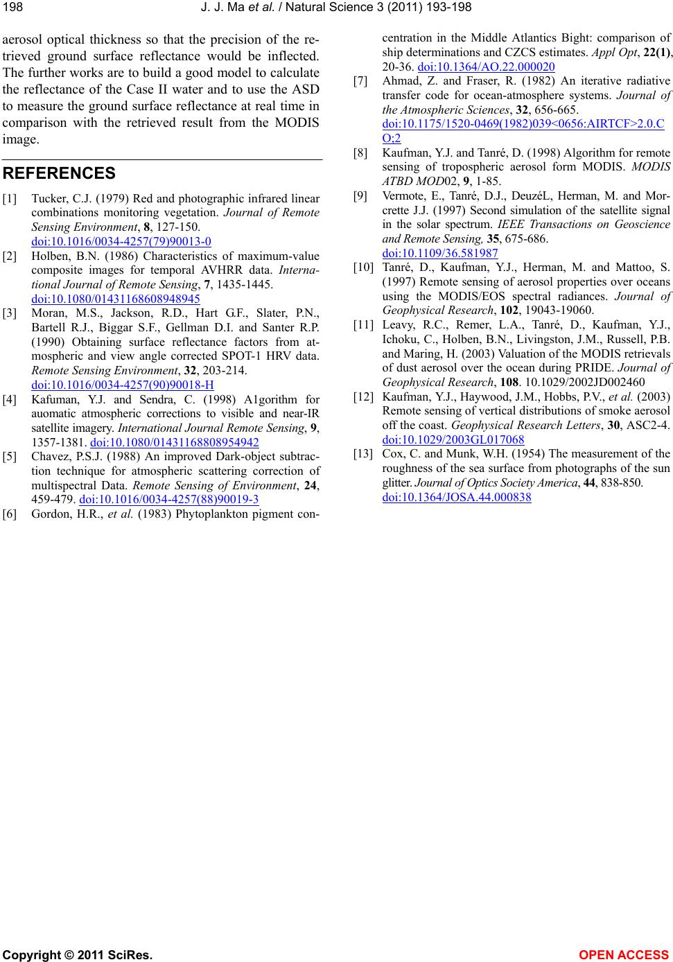 J. J. Ma et al. / Natural Science 3 (2011) 193-198 Copyright © 2011 SciRes. OPEN ACCESS 198 aerosol optical thickness so that the precision of the re- trieved ground surface reflectance would be inflected. The further works are to build a good model to calculate the reflectance of the Case II water and to use the ASD to measure the ground surface reflectance at real time in comparison with the retrieved result from the MODIS image. REFERENCES [1] Tucker, C.J. (1979) Red and photographic infrared linear combinations monitoring vegetation. Journal of Remote Sensing Environment, 8, 127-150. doi:10.1016/0034-4257(79)90013-0 [2] Holben, B.N. (1986) Characteristics of maximum-value composite images for temporal AVHRR data. Interna- tional Journal of Remote Sensing, 7, 1435-1445. doi:10.1080/01431168608948945 [3] Moran, M.S., Jackson, R.D., Hart G.F., Slater, P.N., Bartell R.J., Biggar S.F., Gellman D.I. and Santer R.P. (1990) Obtaining surface reflectance factors from at- mospheric and view angle corrected SPOT-1 HRV data. Remote Sensing Environment, 32, 203-214. doi:10.1016/0034-4257(90)90018-H [4] Kafuman, Y.J. and Sendra, C. (1998) A1gorithm for auomatic atmospheric corrections to visible and near-IR satellite imagery. International Journal Remote Sensing, 9, 1357-1381. doi:10.1080/01431168808954942 [5] Chavez, P.S.J. (1988) An improved Dark-object subtrac- tion technique for atmospheric scattering correction of multispectral Data. Remote Sensing of Environment, 24, 459-479. doi:10.1016/0034-4257(88)90019-3 [6] Gordon, H.R., et al. (1983) Phytoplankton pigment con- centration in the Middle Atlantics Bight: comparison of ship determinations and CZCS estimates. Appl Opt, 22(1), 20-36. doi:10.1364/AO.22.000020 [7] Ahmad, Z. and Fraser, R. (1982) An iterative radiative transfer code for ocean-atmosphere systems. Journal of the Atmospheric Sciences, 32, 656-665. doi:10.1175/1520-0469(1982)039<0656:AIRTCF>2.0.C O;2 [8] Kaufman, Y.J. and Tanré, D. (1998) Algorithm for remote sensing of tropospheric aerosol form MODIS. MODIS ATBD MOD02, 9, 1-85. [9] Vermote, E., Tanré, D.J., DeuzéL, Herman, M. and Mor- crette J.J. (1997) Second simulation of the satellite signal in the solar spectrum. IEEE Transactions on Geoscience and Remote Sensing, 35, 675-686. doi:10.1109/36.581987 [10] Tanré, D., Kaufman, Y.J., Herman, M. and Mattoo, S. (1997) Remote sensing of aerosol properties over oceans using the MODIS/EOS spectral radiances. Journal of Geophysical Research, 102, 19043-19060. [11] Leavy, R.C., Remer, L.A., Tanré, D., Kaufman, Y.J., Ichoku, C., Holben, B.N., Livingston, J.M., Russell, P.B. and Maring, H. (2003) Valuation of the MODIS retrievals of dust aerosol over the ocean during PRIDE. Journal of Geophysical Research, 108. 10.1029/2002JD002460 [12] Kaufman, Y.J., Haywood, J.M., Hobbs, P.V., et al. (2003) Remote sensing of vertical distributions of smoke aerosol off the coast. Geophysical Research Letters, 30, ASC2-4. doi:10.1029/2003GL017068 [13] Cox, C. and Munk, W.H. (1954) The measurement of the roughness of the sea surface from photographs of the sun glitter. Journal of Optics Society America, 44, 838-850. doi:10.1364/JOSA.44.000838 |