

Paper Menu >>
Journal Menu >>
 Journal of Power and Energy Engineering, 2014, 2, 7-12 Published Online April 2014 in SciRes. http://www.scirp.org/journal/jpee http://dx.doi.org/10.4236/jpee.2014.24002 How to cite this paper: Wang, B.C., Han, G.Y. and Zhu, L. (2014) Research on Technology of Electromagnetic Protection for the Generator Control System. Journal of Power and Energy Engineering, 2, 7-12. http://dx.doi.org/10.4236/jpee.2014.24002 Research on Technology of Electromagnetic Protection for the Generator Control System Baocheng Wang, Guyong Han, Lin Zhu Xuzhou Air Force College, Xuzhou, China Email: [email protected] Received December 2013 Abstract Generator control system decides whether the generator can work as usual or not, as well as its stability of performance. Both types of generators control system composed of the transistor and DSP are sensitive to outward electromagnetic interference, directly related to the generator per- formance. In this text, we first analyze the electromagnetic interference threat generator control system of transistor type may face, then design a electromagnetic protection plan for the intake, the panel and the sense organ. This work is of great significance in improving its electromagnetic protection ability and stability of performance. Keywords Generator Control System; Electromagnetic Interference Damage Analysis; Electromagnetic Protection Design 1. Electromagnetic Interference Threat Analysis of Generator Control System Electromagnetic interference mainly gives an effect on the booster in control system. The principle and structure of transistor type are shown by Figure 1. The drive unit composed of triangle wave producer, voltage comparer and driver amplifier circuit, output square wave ub, as drive power switch. Triangle wave producer output triangle waves of certain value and fre- quency, without in-phase problem. Voltage comparer completes the square wave output ua after comparing tri- gonal wave with control voltage u2 and amplifying the signal. The output is low voltage when the value of tri- gonal wave is less than u2, while high voltage on the contrary, just as Figure 2 shows. Triangle wave producer and voltage comparer can be gained by operational amplifier circuit. After processed through power amplifying and opposite phase ua are translated as the drive signal ub. The drive unit is also a proportional tache with the input u2 and the output ua. With coupling interference signals to PID regulate circuit, the scope of trigonal wave changes or control vol- tage becomes uncertain which makes the value of ton/T (expressed as) out of gear, as is shown by Figure 3. Thus, the value of actual excitation current will be restricted by interference signals. What’s more, uncertain value of interference signals result in excitation current regulate chaos, which cause excitation current out of control, then boosters abnormal voltage regulate, after that generators uncertain voltage output, finally power supply vehicle failure in airplanes start-up or offering electrifying check. 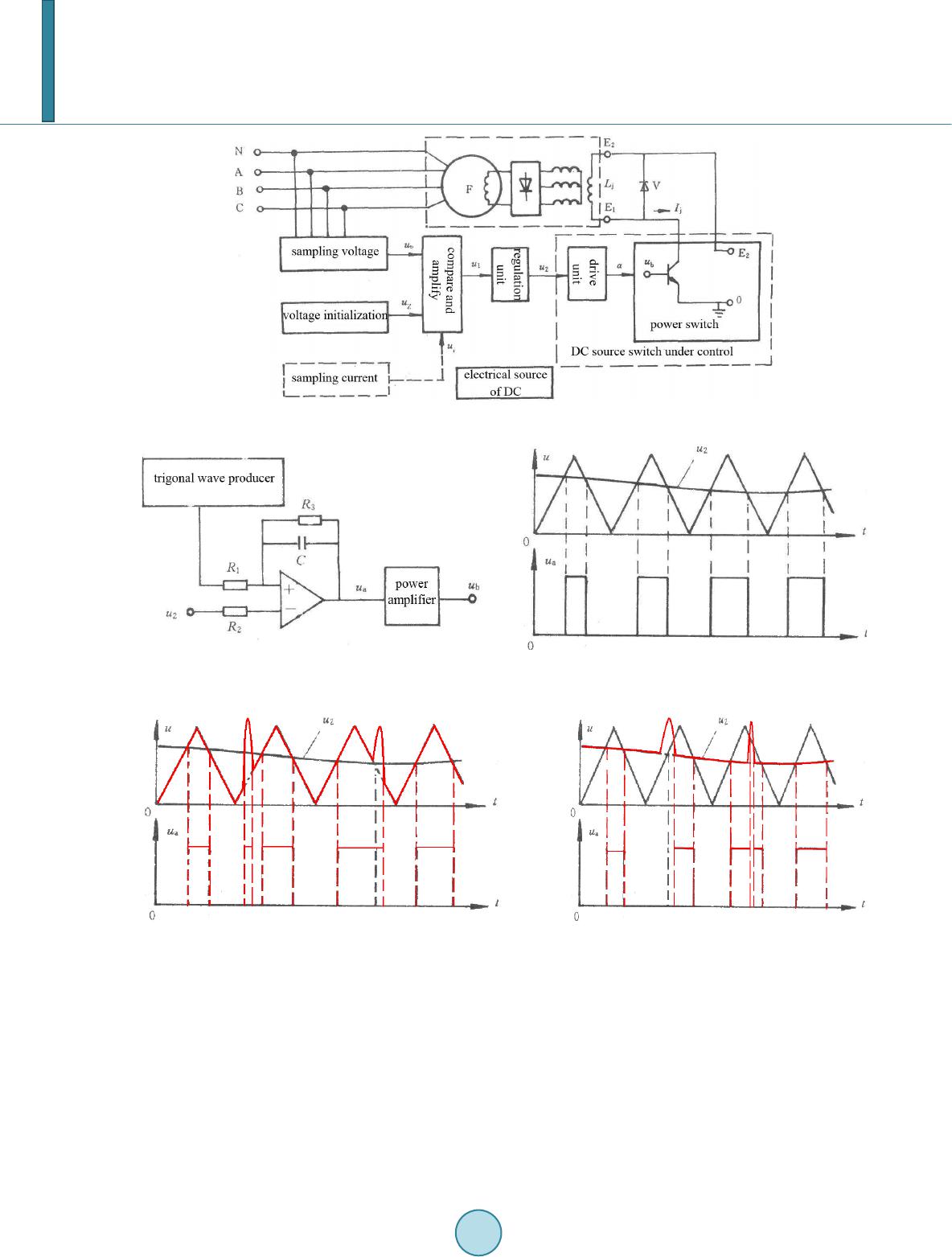 B. C. Wang et al. 8 Figure 1. The system principle and structure frame diagram of transistor type. (a) (b) Figure 2. Structure and wave graph of the driving unit. Figure 3. Compared with wave graphs interfered by signals. 2. Research on Technology of Electromagnetic Protection for Generator Controls System According to the analysis and test results of electromagnetic interfere with generator of transistor type, we carry out a research on electromagnetic protection technique and design a plan for the generator control system. 2.1. Shield Shell for the Intake Electric material is generally used in electromagnetic shield when the electromagnetic field is of high-frequency radiation, with both electric field and magnetic field existing at the same time. In high-frequency segment, well-conducted electric material can shield the inside components from electric field and magnetic field. 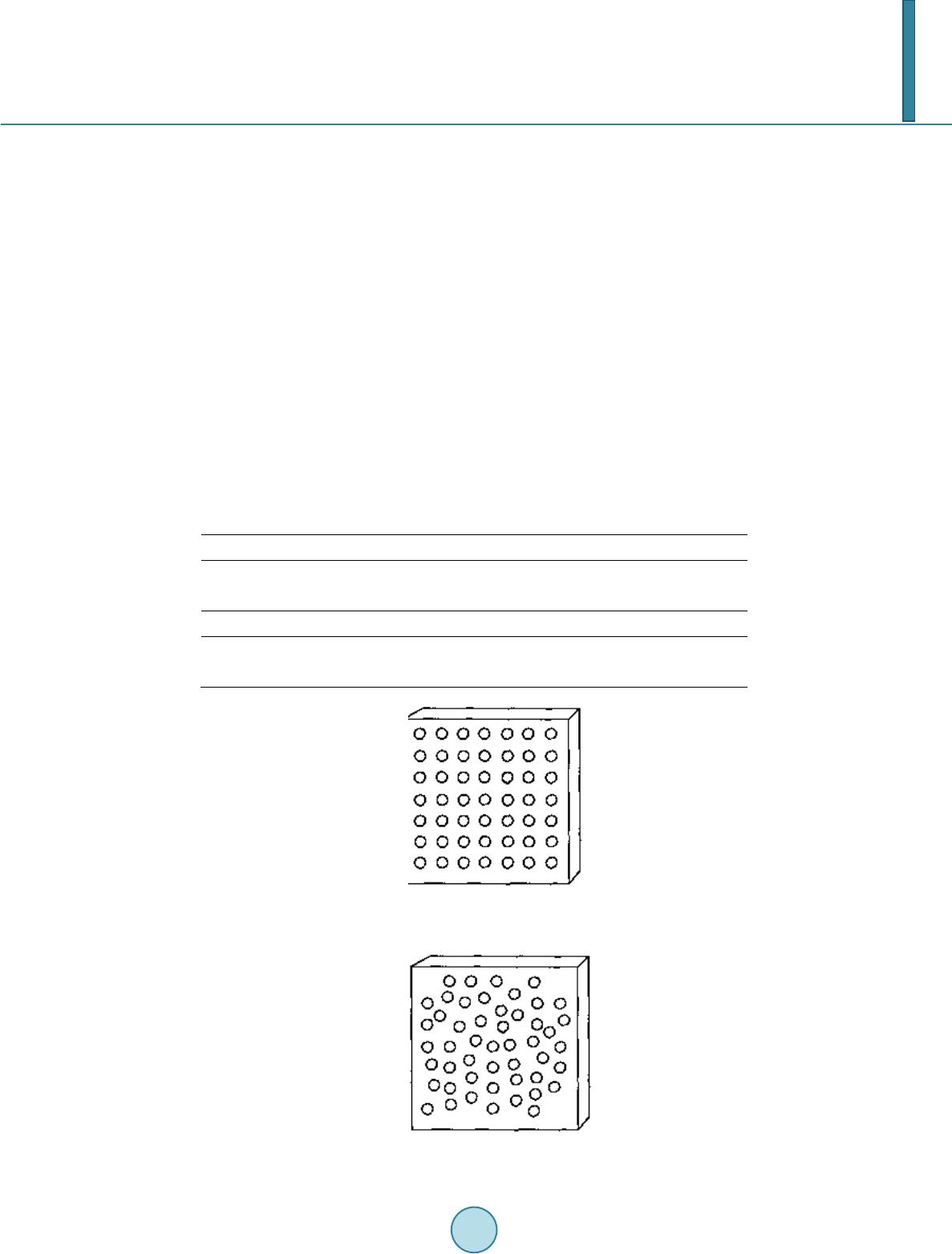 B. C. Wang et al. 9 Table 1 shows the characteristic of usual shield material. According to the relative electromagnetic protection grade, we choose ferromagnetic material of intact structure. For the thickness of the material and the way to dispose joint and grounding directly relative to the shield efficiency, what we must solve actually is the factors engendering electric discontinuity of shield shell, such as the intake, the display window, handling parts, cables drilling through shield shell and so on [1]. The cooling intake on generator, electric discontinuous, brings bad electromagnetic leakage. If we ignore the thickness of shell, its shield efficiency under the worst far electromagnetic field is as follows: 100 20lg20lgSEDD f=−−× (1) In this formula, D expresses the bore diameter and f expresses the frequency of incident electromagnetic wave. According to the formula, the electromagnetic leakage is involved with the size of the bore. The bigger size, the worse shield efficiency. So in the airway design, we replace the original bore by several smaller ones with same hatch area. We choose boring metal plank at low cost, as Figure 4 shows. But when these same bores arrange together regularly (an interval less than λ/2), it will worsen the shield efficiency (to 20lgN/2). Therefore, the bores design must be designed irregularly arranging with unequal mutual intervals, as is shown by Figure 5. 2.2. Grounding Protection for the Control Panel What the generator may suffer is high-frequency electromagnetic wave. Each control loop can be grounded as Table 1. The characteristic of usual shield material. mental silver copper aluminium zinc relative conductivity σr 1.05 1.00 0.61 0.29 relative permeability μr 1 1 1 1 mental brass nickel iron Chemin nickel-plate relative conductivity σr 0.26 0.20 0.17 0.02 relative permeability μr 0.26 0.20 0.17 0.02 Figure 4. Mental plank with original bores. Figure 5. The design for the intake. 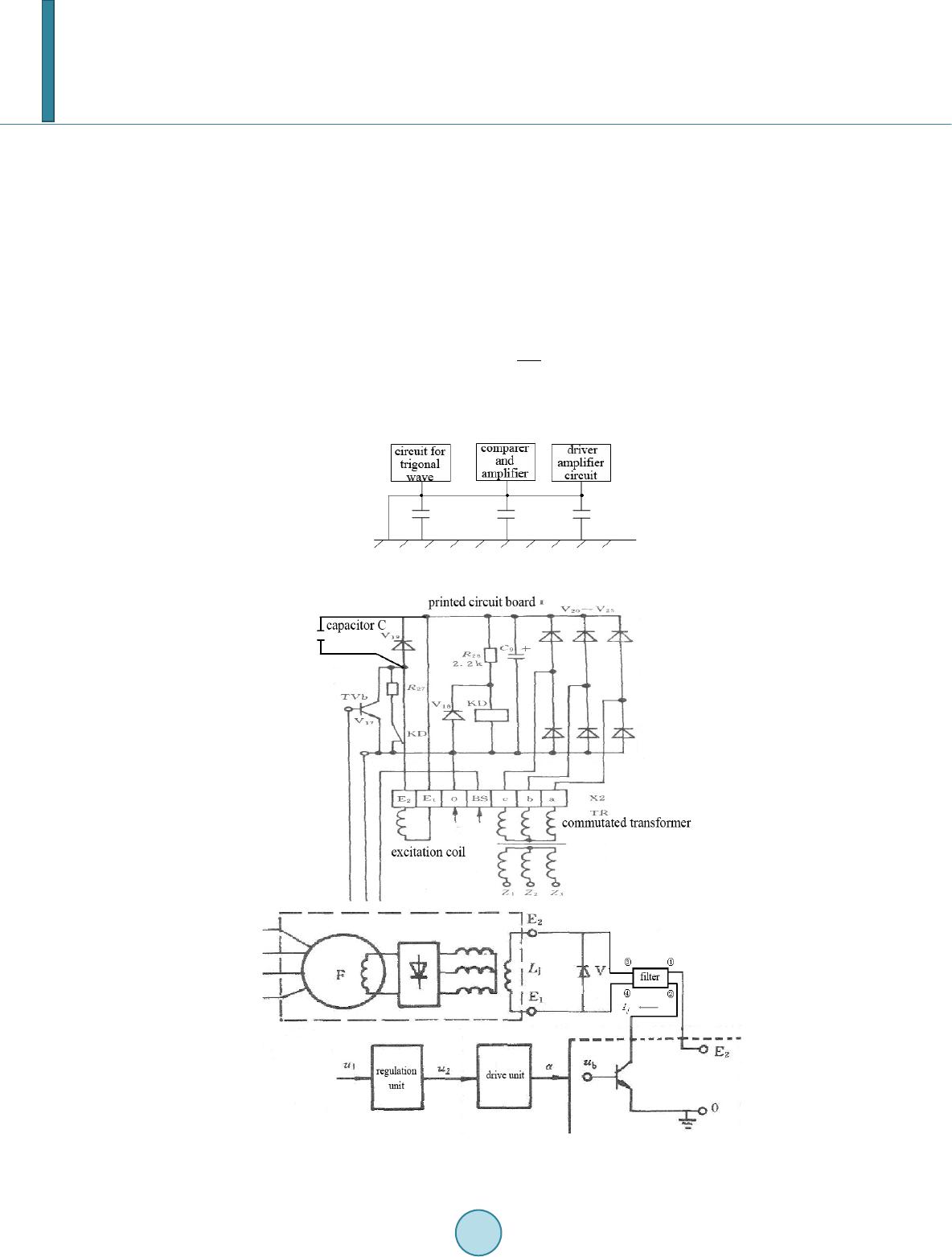 B. C. Wang et al. 10 Figure 6 shows. When some interferential coupling occurs, the interfere will be led to the earth for lower im- pedance of capacity at high frequency, preventing electronic components inside the generator from interference and impact. 2.3. Install a filter in the Sensitive Part 1) As Figure 7 shows. With the both coil ends ( 1 E ~ 2 E ) shunt-wound the filter circuit included capacitor C can absorb the upper parts of surge peak inside the excitation current, consequently weakening or eliminating the interference [2]. The reactance of capacitor C is involved with frequency. Its logarithmic characteristic of breadth and fre- quency is as follows: 1 20lgA( )20lg20lg C C ωω ω == − (2) Obviously, with ω ranges from 2f π to infinity, the effect of voltage attenuation is gradually enhanced. If the source resistance is as equal as load resistance, its insert ullage can be expressed as: Figure 6. The sketch map of grounding. Figure 7. Safeguard for excitation winding. 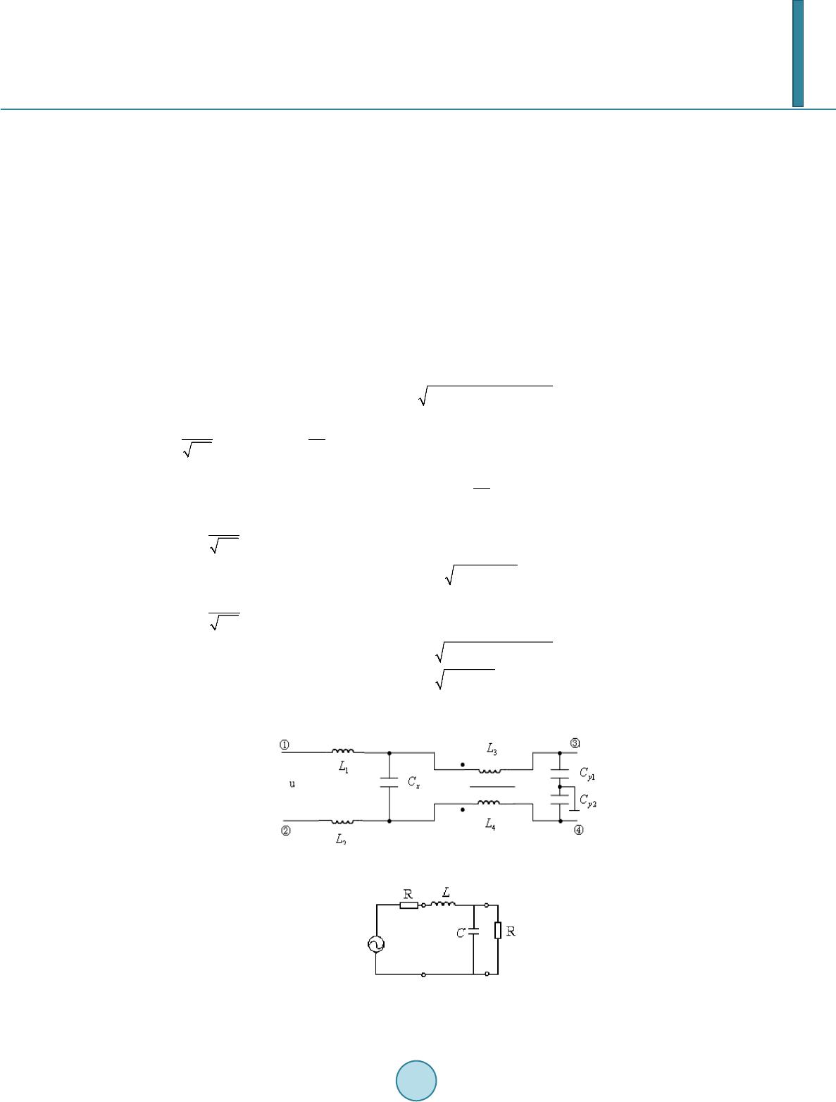 B. C. Wang et al. 11 () 2 10lg 1 A L fRC π = + (3) In this formula, f expresses the work frequency (Hz), R expresses the resistance of source or load ( Ω ) and C expresses capacitance (F). In order to make the power supply vehicle stable of performance under the complicated electromagnetic en- vironment, the value of voltage attenuation is required at least 30 dB when the frequency reaches 1 kHz. If the resistance initialization of the excitation coil is 500 Ω , according to the formula above the valve of capacitance C can be calculated as 20 μF. 2) Install an EMI filter ahead the excitation coil [3] The disadvantage of filter circuit with single capacitor is no more than 6 dB attenuation velocity per each fre- quency span. While we fit single series-wound inductance and single shunt-wound capacitor together, a new type of filter called type L, the value can reach as much as 12 dB per each frequency span. Because the excita- tion current is DC, we choose lowpass. The way of connection is shown by Figure 8. Figure 9 shows the equivalence principle of erase differential-mode and common-mode interferential signal. Its logarithmic characteristic of breadth and frequency is as follows: 2 22 20lgA( )20lg ()(1)RC LC ω ωω =− +− (4) If 0 1 LC ω = and 2 2 0 LC ω ωω = , we can get the results as follows. 0 20lgA( )40lg ω ωω = − (5 ) When 1 LC ω << , 2 20lgA( )20lg ()10RC ωω =− +≈ (6) When 1 LC ω >> , 2 22 22 2 20lgA( )20lg ()() 20lg () 20lg RC LC LC LC ω ωω ω ω =−+ ≈− = − (7) Figure 8. EMI filter. Figure 9. The equivalence prin- ciple of EMI filter.  B. C. Wang et al. 12 With ω ranges from 2f π to infinity, the effect of voltage attenuation is gradually enhanced. If the source resistance is as equal as load resistance, its insert ullage can be expressed as: 2 22 1 10lg (2) 4 A L LLCRC R ω ωω =− ++ (8) In this formula, L expresses filter inductance (H), 2f ωπ = , and terminate frequency 01 2 fLC π = . There are several ways to solve the initialization of L and C in order to reach the minimum value of voltage attenuation at the 1 kHz-frequency. For example, L = 1 mH, while C = 5F. In detail, 12 1L LmH= = , 5 x CF= , 34 1LL mH= = , and 12 5 yy CC F= = . 3. The Tag Research on technology of electromagnetic protection for generator controls system effectively solves the elec- tromagnetic interference with the generator, keeping the performance stability of the generator under compli- cated electromagnetic environment. Particularly in the military realm, it is of great realistic significance in de- veloping the ability of electromagnetic protection for generators and support capability of military equipment. References [1] Lv, W.H., Guo, Y.J., Tang, F.H., Yang, Y. and Chen, Y.F. (2008) Electromagnetic Compatible Principle and Applica- tion Tutorial (version 2). Tsinghua University Press, Beijing. [2] Zhao, G. (2007) The Development Trend of Weapon’s Electromagnetic Compatible Technique. Electronic Engineering of the Warship, 20-22. [3] Zhou, Z.M. and Ji, A.H. (2007) Electromagnetic Compatible Technique. Electro nic Industry Press, Beijing. |