

Paper Menu >>
Journal Menu >>
 Journal of Computer and Communications, 2014, 2, 48-51 Published Online January 2014 (http://www.scirp.org/journal/jcc) http://dx.doi.org/10.4236/jcc.2014.22009 OPEN ACCESS JCC Application of Particle Filter for Vertebral body Extraction: A Simulation Study Hongyan Cui1, Xiaobo Xie1, Shengpu Xu1, Yong Hu1,2 1Institute of Biomedical Engineering, Chinese Academy of Medical Sciences & Peking Union Medical College, Tianjin, PR China; 2Department of Orthopaedics and Traumatology, The University of Hong Kong. Email: [email protected] Received November 2013 ABSTRACT Lumbar vertebra motion analysis provides objective measurement of lumbar disorder. The automatic tracking algorithm has been applied to Digitalized Video Fluoroscopy (DVF) sequence. This paper proposes a new Auto-Tracking System (ATS) with a guide device and a motion analysis to automatically measure human lumbar motion. Digitalized Video Fluoroscopy (DVF) sequence was obtained during flexion-extension lumbar movement under guide device. An extraction of human vertebral body and its motion tracking were developed by particle filter. The results showed a good repeatability, reliability and robustness. In model test, the maximum fiducial error is 3.7% and the repeatability error is 1.2% in translation and the maximal repeatability error is 2.6% in rotation angle. In this simulation study, we employed a lumbar model to simulate the motion of lumber flexion- extension with the stepping translation of 1.3 mm and rotation angle of 1˚. Results showed that the fiducial error was measured as 1.0%, while the repeatability error was 0.7%. The sequence can be detected even noise con- tamination as more as 0.5 of the density. The result demonstrates that the data from the auto-tracking algorithm shows a strong correlation with the actual measurement and that the Vertebral Auto-Tracking System (VATS) is highly repetitive. In the human lumbar spine evaluation, the study not only shows the reliability of Auto-Tra ck- ing Analysis System (ATAS), but also reveals that it is robust and variable in vivo. The VATS is evaluated by the model, the simulated sequence and the human subject. It could be concluded that the developed system could provide a reliable and robust system to detect spinal motion in future medical application. KEYWORDS Vertebral Auto-Tracking System (VATS); Particle Filter; Sequential Important Resampling; Lumbar Spine; Vertebral Body 1. Introduction The lumbar spine instability is an ill-defined clinical ent- ity and most likely is related to the huge number of pa- tients with chronic low back pain. Low back pain is one of the most common disorders associated with absence from work and need for social benefit in modern society. It affects 40% - 85% of adult population in Hong Kong and in industrial countries [1]. Current definitions of spinal instability are based on “a loss of stiffness” [2]. Thus, in an unstable condition a small load results in a large displacement. There has been difficulty in translating this definition into criteria that can be applied to clinical diagnosis and consequent choice of treatment [3]. Clinically, physical signs such as a visible slip, catch, click, or shaking of the section dur- ing motion are commonly used for diagnosing spinal instability [1]. The diagnosis of lumbar instability commonly depends on the chief complaints by patients and plain X-ray radi- ography in two dimensions [4]. Radiographs were taken at several different poses, taking full extension and full flexion as an example, which is a definite and convenient way to obtain some information of the spine motion but not reflects the continuous process of vertebrae. Due to the application and expansion of medical tech- nology [5-7], digitalized video fluoroscopy (DVF) se- quence [8-13] was recommended to image spine motion for kinematic data acquisition. DVF was proposed to investigate spine in kinematics by Breen et al. in 1989 [13]. The advantages are of low level of intervention, low-dose X-ray, and continuously imaging for moving vertebrae. The special imaging technology laid the  Application of Particle Filter for Vertebral body Extraction: A Simulation Study OPEN ACCESS JCC 49 groundwork to record the spine motion in vivo. On the other hand, many biomedical engineering researchers in [9,12,14-20] have analyzed spine biomechanics and pre- sented avenues of identification and mark of vertebral corners as well as tracking algorithm for the vertebrae. Therefore, this new system, named as Auto-Tracking Analysis System (ATAS), was designed to mainly study the lumbar vertebrae’s movement in model and in vivo. The results from the ATAS provide the objective basis for the diagnosis in lumbar disorder. In this study, an attempt was made to gain the motion trajectories of lumbar vertebrae in model to test the ro- bustness and the reliability of the ATAS. Thereafter, the practicability is illustrated by importing a healthy human DVF sequence to the auto-tracking system. 2. Methods 2.1. Image Preprocessing The DVF image sequence is contaminated by noises generated from the DVF system. On the other hand, due to low X-ray dose imaging mode is employed in our se- tup, the contrast between vertebra and surrounding tissue is degraded. In order to enhance the image quality to fa- cilitate automated with regarding to the operation of the software, Landmarking the vertebrae in a DVF sequence is the basis of kinematic analysis whether in automatic or manual tracking. In this paper, the ‘Manual’ panel locat- ing algorithm in the GUI is not used, which will be use- ful for poor DVF sequence images. When the image is poor and cannot be automatically tracked, the markers are placed on the vertebrae’s four corners (two dorsal corners and two ventral corners) on each vertebra body in every frame of the DVF sequence. We can put landmark manually but with time-consuming and error-prone. Nevertheless, the manual tracking is also an important part in the ATAS because the vertebrae images of pa- tients’ DVF sequences are usually presented without sa- tisfactory quality. As well, Trajectory analysis is of great value to the original results once the tracking process finished. The “LPR-RICI Analysis” processes the origi- nal data by local polynomial regression analysis to gain a smooth curve graph. We can obtain the translation and angle of the rotation in a curve graph from “Trajectory Analysis” and “LPR-RICI Analysis”. At last, the data can be output to Excel for further flexible analysis. For more information about operating procedures, please view “Help” on the interface. 2.2. Automated Tracking In the present study, we modify the well validated auto- mated vertebra tracking algorithm using particle filter proposed by Lam et al. [16]. The acquired DVF sequence is in passed to the auto- mated tracking module through the GUI software to es- timate the position and orientation of the vertebrae in each frame of the sequence once the vertebrae of interest have been manually identified in the first frame as shown in Figure 1. The locations of the control points are stored in a control vector C0 . This initialization step defines the vertebra boundary as a close contour for matching with the same vertebra in subsequent frames using the obser- vation model described in Lam et al. [16]. In summary, the posterior distribution of the x- and y- displacement ( ) , tt xy and the orientation variation ( ) t θ of the vertebra from frame t to +1 t were de- tected by particle filter, which are formulated in a state vector as [ ] ,, T t ttt X xy θ = . (1) The particles are then resampled and the state estimate is approximated from the posterior distribution by a set of particles () () t1 {X ,} n nN t tn w = weight with and . Sequential Importance Resampling (SIR) was applied to each time step to prevent the degeneracy problem, and then the weight of each particle n can be calculated as () () (| ) nn t tt pZ X ω ∝ , (2) and , (3) where is a Dirac delta function. The kinematic parameters in state vector at frame t are computed using the minimum mean square error (MMSE) estimate ( )( ) 1 1 ˆNnn t tt n XX N ω = ≈ ∑ . (4) The control vector for frame t , C t , is obtained from the one at -1t , C -1t , and after which Ct and are passed back to the particle filter for the next iteration. 3. Anatomical Lambo-sacral Model Extraction and Performance Assessment The DVF of model was obtained by the previous intro- duced medical system (45 kV, 80 mA, Exposure time: 3ms, Protocol Name: 25 Pediatric < 4y). During the DVF collecting process, the L1-L5 region was maintained within the field of view. For a sharp boundary and pre- venting image from “white-out” in movement, a metal harness was placed on the edge of each vertebra. The assisting device also pulled and pushed the true-to-life model of lumbar vertebral column (Anatomical lam- bo-sacral model, Ortholink LLC, CA 90212, USA) to t X ˆ )(n t w 1 1 )( = ∑ = N n n t w ∑ = −≈ N n n tt n ttt XXZXp 1 )()( :1 )()|( δω )(• δ t X ˆ t X ˆ t X ˆ 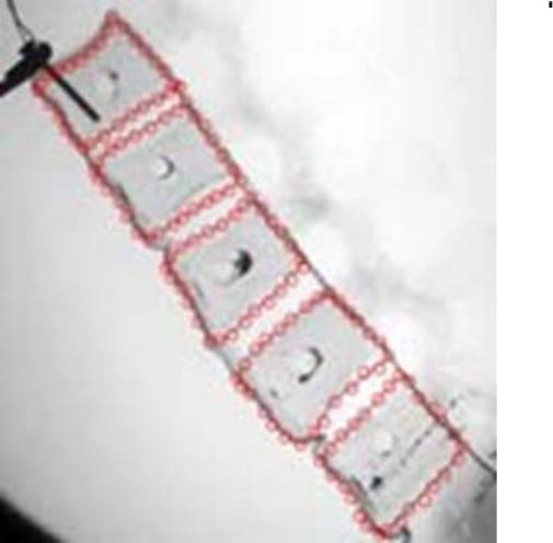 Application of Particle Filter for Vertebral body Extraction: A Simulation Study OPEN ACCESS JCC 50 Figure 1. Image of lumbar model with manually markers. perform sagittal cycling flexion-extension motion. The continuous dynamic lumbar sequence of the model is assessed by the medical system 10 times, which includes 2 integral cycles each time. When the collection was fi- nished, each vertebra trajectory was recorded by a real- time depiction of the vertebral body with rigid fixation pens. About 27 control points were marked on the first frame of each DVF sequence. The more precise the mark is, the more accurate the results will be. An example of locating the control points is shown in Figure 1. Each vertebra used 2000 particles, and 222 ,, ttt xy θ was set as [15,23]. Due to have no elasticity of the discs’ material of the lumbar model, we select the first four moving cycles of DVF sequences to compute the fiducial error and repea- tability error and analyze Test-Retest Reliability. Fig ure 2 arrays partly frames from the DVF sequence of the tracking process. The maximum of the fiducial error is 3.7% in x-translation. In the 20 integral cycles, the aver- age ICC of the x- and y- translation are 0.99 (Std 0.009), 0.99 (Std 0.005) (p < 0.05) respectively between the au- to-tracking and actual measurement. Owing to the same reason to calculate the error, the Root Mean Square differences (RMS) and the Standard Error of the Measurement (SEM) of rotation angle [16], as well as the x- and y-translation of the center among first 4 cycles, calculated to test the variability and ro- bustness of the VATS. The average RMS differences of the x-translation, y-translation and angle of rotation are 0.69 (Std 0.4) mm, 0.64 (Std 0.3) mm, and 0.9˚ (Std 0.3˚) Figure 2. Sequent frames of vertebra flexion. while SEM is 0.47, 0.42, and 0.57˚ (p < 0.05). 4. Discussion The using of particle filter can track the simulated lumbar model and to detect the motion in various noising situa- tion. Breen et al. [18], who introduced DVF to investi- gate spine kinematics firstly, succeeded in using DVF to acquire and analyze lumbar spine motion. Okawa et al. [21] used a sandwich stand to assist in video fluoroscopy acquisition from subjects with and without back pain. Teyhen et al. [9] proposed methods for video fluorosco- py image enhancement and distortion compensated roentgen analysis as well as showing the reliability of their methods and demonstrating an improvement in video fluoroscopy image measurement. However, the main drawback is that the vertebral motions can only be recorded at certain fixed frames or time intervals. Lee et al. [8] evaluated the inter-vertebral motion at certain fixed anatomic ranges of motion of the lumbar spine, which was not a time-dependent parameter. The VATS did not show faults. The translation and angle are accurate in a certain range. The effect of out-of-plane is decreased but there are still minor changes observed in the human DVF se- quence. Eventually, other kinematical parameters such as intervertebral angle and translation can be measured to provide a more comprehensive evaluation. The model and simulation study focus mainly on the reliability and robustness of the Vertebral Auto-Tracking System for the lumbar spine motion. In model test (unit: millimeter in translation and degree in angle), the maxi- mum fiducial error is 3.7% in translation. The maximal repeatability error is 1.2% in translation and 2.6% in ro- tation angle. The result presented the repeatability error with 0.5%, 0.5%, 0.7% in x- and y-translation and rota- tion angle respectively. It proved VATS measurement system with highly repetitive. This simulation study eva- luated the VATS under noise contamination with various noise densities, results from VATS proved the robust of the detection until noise density ≤ 0.5.  Application of Particle Filter for Vertebral body Extraction: A Simulation Study OPEN ACCESS JCC 51 5. Conclusion The proposed Vertebral Auto-Tracking System used par- ticle filter to detect lumbar motion, which can provide a useful tool for medical diagnosis. This study proved the reliability and robustness by a simulation lumbar model. The VATS is evaluated by the model and the simulated sequence. The satisfactory of results proposed the poten- tial value in the future clinical application. REFERENCES [1] O. Shirado, T. Ito, K. Kaneda and T. E. Stra, “Flex- ion-Relaxation Phenomenon in the Back Muscles: a Comparative-Study between Healthy Subjects and Pa- tients with Chronic Low Back Pa in,” American Journal of Physical Medicine & Rehabilitation, Vol. 74, No. 2, 1995, pp. 139-144. [2] M. M. Panjabi and A. A. White, “Kinematics of the Spine,” In: M. M. Panjabi and A. A. White, Eds., Clinical Biomechanics of the Spine, 2nd Edition, J. B. Lippincott Co., Philadelphia, 1990, pp. 85-126. [3] J. W. Frymoyer and D. K. Selby, “Segmental Instability: Rationale for Treatment,” In: G. R. Bell, S. W. Wiesel, J. N. Weinstein, H. N. Herkowitz and J. Dvorak, Eds., The Lumbar Spine, 2nd Edition, W. B. Saunders Co., Phila- delphia, 1996, pp. 43-52. [4] F. Ringel, M. Stoffel, C. Stüer and B. Meyer, “Minimally Invasive Transmuscular Pedicle Screw Fixation of the Thoracic and Lumbar Spine,” Neurosurgery, Vol. 59, No. 4, 2006, pp. ONS-361-ONS-367. [5] J. M. Olsewski, E. H. Simmons, F. C. Kallen, F. C. Men- del, C. M. Severin and D. L. Berens, “Morphometry of the Lumbar Spine: Anatomical Perspectives Related to Transpedicular Fixation,” Journal of Bone and Joint Sur- gery American, Vol. 72, No. 4, 1990, pp. 541-549. [6] M. M. Panjabi, V. Goel, T. Oxland, K. Takata, J. Duran- ceau, M. Krag, et al., “Human Lumbar Vertebrae: Quan- titative Three-Dimensional Anatomy,” Spine (Phila Pa 1976), Vol. 17, No. 3, 1992, pp. 299-306. [7] M. M. Panjabi, K. Takata, V. Goel, D. Federico, T. Oxl- and, J. Duranceau, et al., “Thoracic Human Vertebrae. Quantitative Three-Dimensional Anatomy,” Spine (Phila Pa 1976), Vol. 16, No. 8, 1991, pp. 888-901. [8] S. W. Lee, K. W. Wong, M. K. Chan, H. M. Yeung, J. L. Chiu and J. C. Leong, “Development and Validation of a New Technique for Assessing Lumbar Spine Motion,” Spine (Phila Pa 1976), Vol. 27, No. 8, 2002, pp. E215- E20. [9] D. S. Teyhen, T. W. Flynn, A. C. Bovik and L. D. Abra- ham, “A New Technique for Digital Fluoroscopic Video Assessment of Sagittal Plane Lumbar Spine Motion,” Spine (Phila Pa 1976), Vol. 30, No. 14, 2005, pp. E406- E413. [10] A. Breen, R. Allen and A. Morris, “A Digital Video Flu- oroscopic Technique for Spine Kinematics,” Journal of Medical Engineering & Technology, Vol. 13, No. 1-2, 1989, pp. E109-E113. http://dx.doi.org/10.3109/03091908909030208 [11] D. Vander Kooi, G. Abad, J. R. Basford, T. P. Maus, M. J. Yaszemski and K. R Kaufman, “Lumbar Spine Stabiliza- tion with a Thoracolumbosacral Orthosis: Evaluation with Video Fluoroscopy,” Spine (Phila Pa 1976), Vol. 29, No. 1, 2004, pp. 100-104. [12] A. C. Breen, R. Allen and A. Morris, “Spine Kkinematics: a Digital Videofluoroscopic Technique,” Journal of bio- medical engineering, Vol. 11, No. 3, 1989, pp. 224-228. http://dx.doi.org/10.1016/0141-5425(89)90146-5 [13] K. Takayanagi, K. Takahashi, M. Yamagata, H. Moriya, H. Kitahara and T. Tamaki, “Using Cineradiography for Continuous Dynamic-motion Analysis of the Lumbar Spine,” Spine, Vol. 26, No. 17, 2001, pp. 1858-1865. [14] M. Panjabi and D. Chang, “An Analysis of Errors in Ki- nematic Parameters Associated with in Vivo Functional Radiographs,” Spine (Phila Pa 1976), Vol. 17, No. 2, 1992, pp. 200-205. [15] Y. Zheng, M. S. Nixon and R. Allen, “Automated Seg- mentation of Lumbar Vertebrae in Digital Videofluoros- copic Images,” IEEE Transactions on Medical Imaging, Vol. 23, No. 1, 2004, pp. 45-52. [16] S. C. B. Lam, B. McCane and R. Allen, “Automated Tracking in Digitized Videofluoroscopy Sequences for Spine Kinematic Analysis,” Image and Vision Computing, Vol. 27, No. 10, 2009, pp. 1555-1571. [17] P. Bifulco, M. Cesarelli, R. Allen and M. Bracale, “Au- tomatic Extraction of Kinematic Parameters from Vi- deofluoroscopic Sequences of the Spine,” Proceedings of Health Telematics, Naples, 1995, pp. 147-148. [18] J. M. Muggleton and R. Allen, “Automatic Location of Vertebrae in Digitized Videofluoroscopic Images of the Lumbar Spine,” Medical Engineering & Physics, Vol. 19, No. 1, 1997, pp. 77-89. [19] A. Thorkeldsen and A. C. Breen, “Gray Scale Range and the Marking of Vertebral Coordinates on Digitized Radi- ographic Images,” Journal of manipulative and physio- logical therapeutics, Vol. 17, No. 6, 1994, pp. 359-363. [20] C. Cardan and R. Allen, “Measurement of Spine Motion for Diagnosis of Mechanical Problems,” Journal of Computer Simulation & Modelling in Medicine, Vol. 1, No. 1, 2000, pp. 15-19. [21] A. Okawa, K. Shinomiya, H. Komori, T. Muneta, Y. Arai, and O. Nakai, “Dynamic Motion Study of the Whole Lumbar Spine by Videofluoroscopy,” Spine (Phila Pa 1976), Vol. 23, No. 16, 1998, pp. 1743-1749. |