

Paper Menu >>
Journal Menu >>
 Open Journal of Civil Engineering, 2013, 3, 242-250 Published Online December 2013 (http://www.scirp.org/journal/ojce) http://dx.doi.org/10.4236/ojce.2013.34029 Open Access OJCE TransCAD and GIS Technique for Estimating Traffic Demand and Its Application in Gaza City Essam Almasri, Mohammed Al-Jazzar Department of Civil Engineering, Islamic University of Gaza, Gaza, Palestine Email: [email protected] Received September 11, 2013; revised October 11, 2013; accepted October 18, 2013 Copyright © 2013 Essam Almasri, Mohammed Al-Jazzar. This is an open access article distributed under the Creative Commons Attribution License, which permits unrestricted use, distribution, and reproduction in any medium, provided the original work is properly cited. ABSTRACT In the early nineties of the last century, the transportatio n system in Gaza Strip was born and new infrastructure projects, especially road networks, were constructed. However, the construction lacked efficient application of a transportation planning process. Transportation planning relies on traffic demand forecasting process. The conventional process is impeded by extensive amount of socioeconomic data. One of the most widely-used models which mitigate this problem is the TransCAD Model. This model is rarely used in Gaza Strip for traffic demand forecasting, and most of the prac- tices depend mainly on a constant growth rate of traffic. Therefore, the main objective of this research is to apply this model in Gaza City for traffic estimation. This model estimates the origin-destination matrix based on traffic count. The traffic count was carried out at 36 intersections distributed around Gaza City. The results of traffic flow estimation ob- tained from TransCAD are assigned to the Gaza maps using the GIS techniques for spatial analysis. It is shown that the most congested area at present is the middle of the city especially at Aljala-Omer Almokhtar intersection. Therefore, improvement scenarios of this area should be carried out. The results of calibration of traffic flow estimation show that the differences between the estimated and the actual flows were less than 10%. In addition, network evaluation results show that the network is expected to be more congested in 2015. This work can be used by transportation planners for testing any network improvement scenarios and for studying their network performance. Keywords: Transportation Planning; Traffic Demand Forecasting; Origin-Destination Estimation; Gaza; GIS 1. Introduction Gaza Strip is situated at the southern part of the Palestin- ian Territories. As shown in Figure 1, it includes five governorates namely, Rafah, Khan-Younis, Middle, Gaza and North Governorates [1]. The area of Gaza Strip is about 365 k m2. It is a narrow coastal strip of land with a length of 40 km along the Mediterranean Sea in the Northwest di rection. It has 58 km borders with An-Naqa v Desert to the East and South and 12 km with Egypt to the Southwest. It takes its name from its main city Gaza [2]. According to the census conducted by the Palestinian Central Bureau of Statistics (PCBS), the total number of population of Gaza Strip at mid 2011 was 1.59 millions. Gaza is the most densely populated governorate in Gaza Strip with a density of 0.75 inhabitants/hectare. The area of Gaza City is 7259.3 hectares and the number of popu- lation at mid 2011 is 552,0 00 [3]. Gaza Strip transportation system is limited by small and poorly developed road network. Before 1967, it had a single railway line running from North to South of Gaza Strip along its centre. However, currently it disap- pears and little trackage remains. There is only a small port which is limited to fishermen. Gaza International Airport was opened in November 1998; however, it was closed in October 2000. After the arrival of the Palestin- ian National Authority from Diasporas in the early nine- ties of the last century, the transportation system in Gaza Strip was born and a dramatic and unprecedented in- crease in the possession of the vehicles was observed. In consequence of that, new infrastructure projects, espe- cially road networks, were constructed. However, the construction lacked efficient application of a transporta- tion planning process. This led to deficiency in adopting the suitable transport policies to mitigate the transporta- tion problems resulting from urbanization and rapid in- crease of population [4]. Transportation planning relies on travel demand fore-  E. ALMASRI, M. AL-JAZZAR 243 Figure 1. Governorates of Gaza Strip [1]. casting which involves prediction of the number of vehi- cles or travellers that will use a particular transportation facility in future. Since 1950’s, many travel demand forecasting processes were developed, including conven- tional four-stage travel demand forecasting process. This process begins with collection of extensive data on land use, socioeconomic, demographic, and network charac- teristics [5]. The four steps of the process are sequenced as trip generation, trip distribution, mode choice, and traffic assignment. Trip generation determines the num- ber of trips starting or ending at an area (zone) within a given time such as per day or per hour. It is based on determining a relationship between trip making and land uses, household demographics, and other socioeconomic factors. Trip distribution is the process by which the planner calculates the pattern of trips between the zones. It describes the number or proportion of trips from an origin zone spread amongst all destination zones. Mode choice computes the patterns of trips between origin and destination zones that use a particular transportation mode. Traffic assignment determines the volume of travel for each individual movement at intersections of the transportation network [6]. From the time when the convention al four-stage travel demand forecasting was developed, a number of highly critical reviews to the model have been seen. In response to criticisms, improvements have been made on the four- stage modeling approach and new modeling approaches have come out [7]. According to [7], few of the devel- oped models have already been tried in cities of devel- oping countries. An example of work is shown in [8] in which different Work-Trip Mode-Choice Models for South Africa were tested. A second example is shown in [9] in which different trip generation models in develop- ing countries were analyzed and calibrated. A third ex- ample is shown in [10] in which two types of gravity model for trip distribution in India were calibrated. A fourth is [11] which is a transport study of Amman, Jor- dan. One of the criticisms of th e sequential four-step model is the extensive amount of land use, socioeconomic, and demographic data needed for the first step of trip genera- tion. Because of that, many models have been developed which skipped this step and started directly from step 2. They estimate the origin-destination (O-D) matrix based on traffic counts. Traffic counts are much easier to obtain and are often already available for other traffic related purposes. Therefore, many computer models have been proposed and applied for O-D matrix estimation to inves- tigate the relationship between traffic counts and O-D matrix. One of the most widely-used models is the TransCAD Model [12]. This model is rarely used in Gaza Strip for traffic de- mand forecasting, and most of the practices depend mainly on a constant growth rate of traffic. Therefore, the main objective o f this research is to apply the Tran sCAD model for traffic estimation. The results will be assigned to the Gaza maps using the GIS techniques available in TransCAD for spatial analysis to be used as guidelines for transportation planner to determine the congested locations in Gaza, and hence to help in developing poli- cies for congestion mitigation . 2. Methodology In order to achieve the objectives of this study the work is divided into six phases. The first phase is data collec- tion. The data includes network road characteristics and traffic data for the base year. The traffic count was car- ried out in 18/4/2010 by more than one hundred observ- ers under the supervision of the researchers. The count was conducted to from 7:00 am to 12:00 am to deter- mine the exact network peak hour. It was done at 36 in- tersections distributed around Gaza City as shown in Figure 2. Figure 2. Locations of traffic counts in Gaza City. Open Access OJCE  E. ALMASRI, M. AL-JAZZAR 244 The second phase is network building and data enter- ing. An aerial photo of Gaza was geo-referenced and digitized using ArcGIS. The resulted ESRI shape file was transferred into TransCAD and used as a background to draw the network and the zones. Zoning system for Gaza City was very essential for the O-D matrix estimation and traffic assignment. For that purpose, the land use characteristics of the City was studied. The third phase is matrix estimation for the base year. It is done using TransCAD Model which is based on Nielsen’s Model [13], who independently developed it as a procedure for TransCAD 2.1. The model has the ad- vantages of handling counts as stochastic variables, as well as working with any traffic assignment method. Thus, it is appealing for use with the Stochastic User Equilibrium Assignment method, as well as with User Equilibrium Assignment. Nielsen’s model is an iterative (or bi-level) process that switches back and forth be- tween a traffic assignment stage and a matrix estimation stage [14]. To use the O-D Matrix Estimation procedure, the base O-D matrix and a geographic file of both area and line laye rs are prepar ed. In line geographic file, each link data should be input, and a network for the line layer should be created. It should include all the relevant at- tributes. In area geographic file, connectors of zones’ centroids must be created to connect line and area geo- graphic layer. Because there is no available prior O-D matrix, a unit matrix (each O-D pair has a value of 1) was used as initial matrix. Based on traffic counts at the intersections, the O-D matrix was estimated and vali- dated. A base O-D matrix serves two purposes. The first purpose is to set the dimensions for the output matrix. The second purpose is to provide initial values for the estimated O-D matrix. The fourth phase is model calibration to ensure good representation of the traffic network. The aim is to esti- mate O-D matrix that should be as real as possible. Model calibration was conducted by adjusting locations of zones’ connectors, locations of zones’ centroids and turn penalties. The observed traffic flow and the modeled traffic flow at the intersections using the traffic assign- ment should be close to each other. Traffic flow differ- ence of 10% could be acceptable. The fifth phase is future O-D matrix estimation. For that purpose, it is recommended to use uniform growth factor method by multiplying all O-D pairs by the same amount as shown in Equation (1) [6]: ijf ijppf TTM (1) where, ijf is trips for O-D pair ij in future year f; ijp is trips for O-D pair ij in present year p; and T T p f M is expected growth in trips between year f and p. When information about the expected growth in trips produced in each zone is available, the singly constrained growth factor method might be used ([6,15]). This is performed by multiplying different growth factors to different rows (or columns) in the O-D matrix. Accord- ing to [6,16], the growth factors might be determined based on land use or socioeconomic data. Because of little amount of socioeconomic and land use data, fore- casting in this research is simply based on uniform growth factor method. The estimates of rate of growth in vehicle ownership over the forecasting period are used to develop the end product of passenger traffic trip matrix. They are directly input to the modelling process as a value by which existing base year vehicle trip matrices are factored to develop future year trip matrices. The sixth phase is network evaluation. TransCAD model offers three network performance measures. The first one is vehicles hours of travel which is the summa- tion of travel time spent by all vehicles in the network. The second one is the total vehicle kilometers travelled which is the summation of the total distance travelled by all the vehicles over the network in one hour. These two measures can be used in different scenario evaluation and comparison, where the best scenario should have the lowest values. The third performance measure is volume over capacity ratio which is a direct indication of the network level of service. 3. Results and Analysis This section presents the results obtained when applying the methodology discussed in the previous section. It includes five parts. The first one presents geometric and traffic data. The second part concerns the network build- ing. The third part discusses the obtained results of base year O-D matrix estimation and model calibration, while the fourth part discusses the results of future O-D matrix estimation. The last part presents the results of network evaluation. 3.1. Data The geometric data collection focused on the main streets and intersections which were involved in th e traffic count. Figure 2 presents the intersectio ns’ names and locations. Geometric data for some of the intersections are pre- sented in Table 1 which are the intersections located along Aljala Street. The first column is intersection serial number. The second column shows the names of the in- tersections while the third shows the names of the streets intersecting Aljala Street. The next columns present the number of lanes in each approach before arriving at each intersection. It is noted that the lanes before arriving in- tersections is less than at intersections because of either widening of the intersections or using nearside lane for parking between intersections. Table 2 presents the car- riageway widths of the streets. Open Access OJCE  E. ALMASRI, M. AL-JAZZAR Open Access OJCE 245 Table 1. Geometric data for intersections located along Aljala Street. Intersection Number of lanes Before intersection At intersection No. Name Aljala St. with… NB SB EB WB NB SB EB WB 25 El-Tiaran Jamal Abed Alnaser - 2 2 2 - 3 3 2 20 El-Saraya Omer Almokhtar st 2 2 2 2 3 3 3 3 13 Dabeet Alwehda 2 2 2 2 3 3 2 2 7 El-Ghifary Alababidy 2 2 2 2 3 3 3 3 4 1st st. 1st st. 2 2 2 2 3 3 3 3 3 Akher Aljala 3rd st. 2 2 2 2 2 2 2 2 Table 2. Carriageway widths of streets intersecting Aljala Street. No. Streets names Carriageway width (m) 1 Aljala Street 10 2 Jamal Abed Alnaser Street 8 3 Omer Almokhtar Street 10 4 Alwehda Street 6 5 Alababidy Street 9.5 6 The 1st Street 9 7 The 3rd Street 7 The traffic count at the 36 intersections was carried out manually and simultaneously by 132 observers. At each approach in each intersection, an observer stood and counted vehicles that left the intersection and went left, through or right. Figure 3 presents locations of the counted intersections. The flows at the intersections are shown in Figure 3 on GIS spatial map where the diame- ter of the circle represents the summation of traffic flow for all approaches at the intersection. Based on this rep- resentation, it can be easily seen that the most congested area is the middle of the city and that the intersections and the streets in this area should be taken into consid- eration. Figure 4 presents graphically the values of total five- hour traffic flow and the peak hour flow at the intersec- tions. It is observed that Aljala-Omer Almokhtar inter- section (Alsaraia) has the highest traffic flow. On the other side, Alrashed-the third intersection (Almokhabarat) has the lowest traffic flow. Network peak hour flow is essential input in TransCAD to model the Gaza traffic network. Based on the traffic count conducted to from 7:00 am to 12:00 am, the network peak hour was be- tween 7:30 and 8:30 am. 3.2. Network Building Network building in TransCAD is done by constructing line geographic and area geographic layers. In line geo- graphic layer, roads are represented by their centerlines. For that purpose, an aerial photo of Gaza City was geo-referenced and then the roads were digitized out of the map by ArcGIS as shown in Figure 5. The process of representing an image by a discrete set of its points is known as the digitization process. The resulted ESRI shape file was transferred into TransCAD. The geo-ref- erenced ESRI shape file was then used as a background to draw the network. A zone area geographic layer is needed to complete the traffic network modeling. Thirty four zones were built in this layer. The resulting layer of zones and streets is shown in Figure 6. The selection of zonal boundaries was based on the following criteria that were adopted in previous studies such as [11,17]: The area of Central Business District (CBD) should have relatively small zone sizes while larger zone sizes are used for outside CBD. This is due to the dense trip activities within CBD. The use of main roads as zone boundaries should be avoided to facilitate the trip assigning for the zones on or near the main roads. Each zone should have homogenous socio-economic characteristics. The zoning process should take the Municipality dis- trict’s boundaries into consideration. 3.3. Base Year Matrix Estimation and Model Calibration Based on the process of matrix estimation discussed in the methodology section, the estimated O-D matrix for base year 2010 is shown in Table 3. The number of columns and rows is the number of zones. The zones in 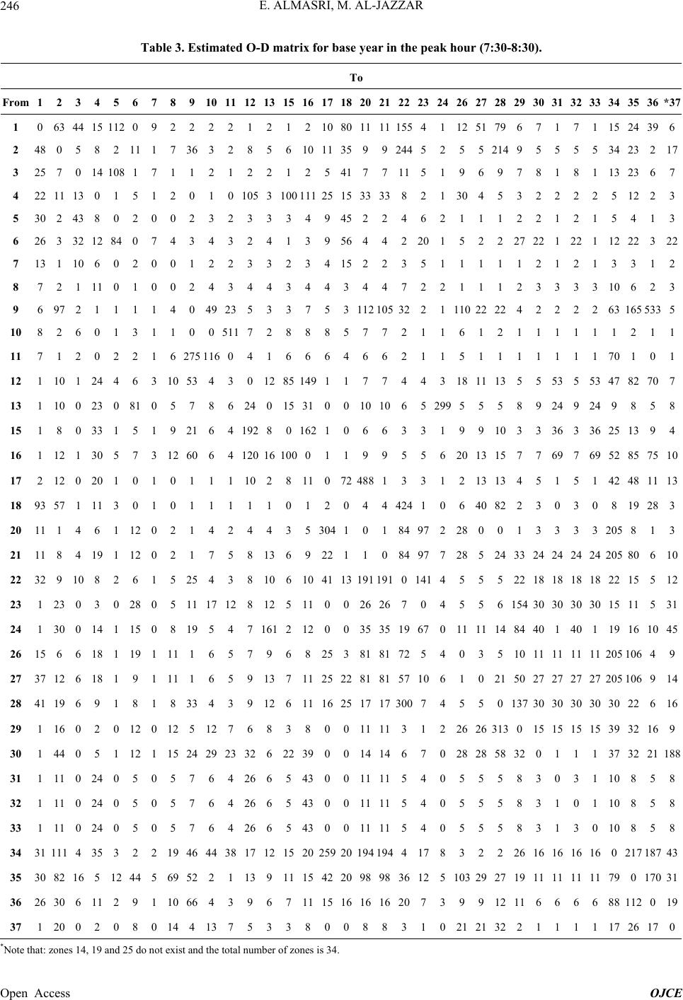 E. ALMASRI, M. AL-JAZZAR 246 Table 3. Estimated O-D matrix for base year in the peak hour (7:30-8:30). To From 1 2 3 4 5 6 7 89 10 11 12 1315161718202122232426272829 30 31 32 33 343536*37 1 0 63 44 15 112 0 9 22 2 2 1 21210801111155411251796 7 1 7 1 1524396 2 48 0 5 8 2 11 1 7 36 3 2 8 56 101135 9924452552149 5 5 5 5 3423217 3 25 7 0 14 108 1 7 11 2 1 2 212541 7711519697 8 1 8 1 132367 4 22 11 13 0 1 5 1 20 1 0 105 31001112515333382130 453 2 2 2 2 51223 5 30 2 43 8 0 2 0 02 3 2 3 334945 224621112 2 1 2 1 5413 6 26 3 32 12 84 0 7 43 4 3 2 413956 44220152227 22 1 22 1 1222322 7 13 1 10 6 0 2 0 01 2 2 3 323415 223511111 2 1 2 1 3312 8 7 2 1 11 0 1 0 02 4 3 4 43443447221112 3 3 3 3 10623 9 6 97 2 1 1 1 1 40 49 23 5 3375311210532 2111022224 2 2 2 2 631655335 10 8 2 6 0 1 3 1 10 0 511 7 28885772116121 1 1 1 1 1211 11 7 1 2 0 2 2 1 6275 116 0 4 16664662115111 1 1 1 1 70101 12 1 10 1 24 4 6 3 1053 4 3 0 1285149117744318 11135 5 53 5 53 4782707 13 1 10 0 23 0 81 0 57 8 6 24 015 310010 1065 299 5558 9 24 9 24 9858 15 1 8 0 33 1 5 1 9 21 6 4 192 80162106633199 10 3 3 36 3 36 2513 94 16 1 12 1 30 5 7 3 1260 6 4 120 16100 0119955620 13 157 7 69 7 69 52 857510 17 2 12 0 20 1 0 1 01 1 1 10 28 110 72488133121313 4 5 1 5 1 42481113 18 93 57 1 11 3 0 1 01 1 1 1 10120444241064082 2 3 0 3 0 819283 20 11 1 4 6 1 12 0 21 4 2 4 435304101 8497228 001 3 3 3 3 205813 21 11 8 4 19 1 12 0 21 7 5 8 1369221108497728524 33 24 24 24 24 20580610 22 32 9 10 8 2 6 1 5 25 4 3 8 10 61041131911910141455522 18 18 18 18 2215512 23 1 23 0 3 0 28 0 5 11 17 12 8 1251100 2626704556154 30 30 30 30 15115 31 24 1 30 0 14 1 15 0 819 5 4 7 161212003535196701111 1484 40 1 40 1 19161045 26 15 6 6 18 1 19 1 111 6 5 7 96825381 81 725403510 11 11 11 11 205106 49 27 37 12 6 18 1 9 1 111 6 5 9 13711 25 228181571061021 50 27 27 27 27 205106914 28 41 19 6 9 1 8 1 8 33 4 3 9 12 6111625171730074550137 30 30 30 30 30226 16 29 1 16 0 2 0 12 0 125 12 7 6 8380011113122626313 0 15 15 15 15 3932169 30 1 44 0 5 1 12 1 1524 29 23 32 62239 001414 67028285832 0 1 1 1 373221188 31 1 11 0 24 0 5 0 57 6 4 26 65 4300 11115405558 3 0 3 1 10858 32 1 11 0 24 0 5 0 57 6 4 26 65 4300 11115405558 3 1 0 1 10858 33 1 11 0 24 0 5 0 57 6 4 26 65 4300 11115405558 3 1 3 0 10858 34 31 111 4 35 3 2 2 1946 44 38 17 12 152025920194194417832226 16 16 16 16 021718743 35 30 82 16 5 12 44 5 6952 2 1 13 911154220989836125103 292719 11 11 11 11 790170 31 36 26 30 6 11 2 9 1 1066 4 3 9 67 1115161616207399 1211 6 6 6 6 88112019 37 1 20 0 2 0 8 0 144 13 7 5 3380088310 212132 2 1 1 1 1 1726170 *Note that: z ones 14, 19 and 25 do not exist and the total number of zones is 34. Open Access OJCE 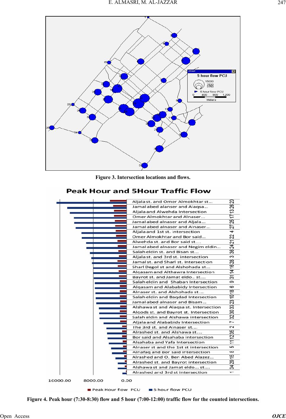 E. ALMASRI, M. AL-JAZZAR 247 Figure 3. Intersection locations and flows. Figure 4. Peak hour (7:30-8:30) flow and 5 hour (7:00-12:00) traffic flow for the counted intersections. Open Access OJCE 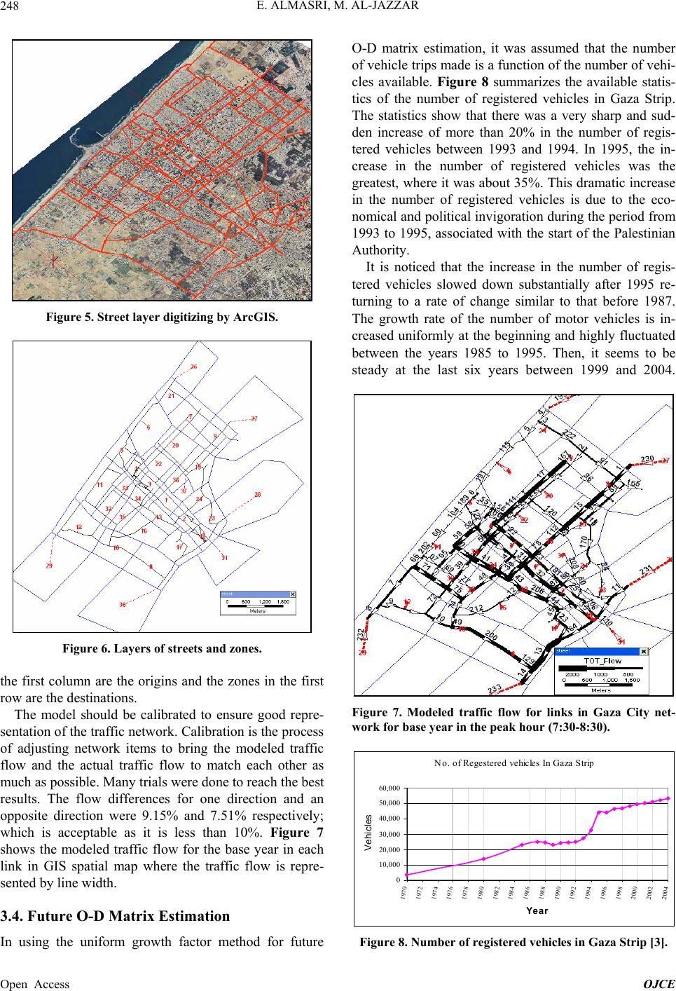 E. ALMASRI, M. AL-JAZZAR Open Access OJCE 248 Figure 5. Street layer digitizing by ArcGIS. Figure 6. Layers of streets and zones. the first column are the origins and the zones in the first row are the destinations. The model should be calibrated to ensure good repre- sentation of the traffic network. Calibratio n is the process of adjusting network items to bring the modeled traffic flow and the actual traffic flow to match each other as much as possible. Many trials were done to reach the best results. The flow differences for one direction and an opposite direction were 9.15% and 7.51% respectively; which is acceptable as it is less than 10%. Figure 7 shows the modeled traffic flow for the base year in each link in GIS spatial map where the traffic flow is repre- sented by line width. 3.4. Future O-D Matrix Estimation In using the uniform growth factor method for future O-D matrix estimation, it was assumed that the number of vehicle trips made is a function of the number of vehi- cles available. Figure 8 summarizes the available statis- tics of the number of registered vehicles in Gaza Strip. The statistics show that there was a very sharp and sud- den increase of more than 20% in the number of regis- tered vehicles between 1993 and 1994. In 1995, the in- crease in the number of registered vehicles was the greatest, where it was abou t 35%. This dramatic increase in the number of registered vehicles is due to the eco- nomical and political inv igoration during the period from 1993 to 1995, associated with the start of the Palestinian Authority. It is noticed that the increase in the number of regis- tered vehicles slowed down substantially after 1995 re- turning to a rate of change similar to that before 1987. The growth rate of the number of motor vehicles is in- creased uniformly at the beginning and highly fluctuated between the years 1985 to 1995. Then, it seems to be steady at the last six years between 1999 and 2004. Figure 7. Modeled traffic flow for links in Gaza City net- work for base year in the peak hour (7:30-8:30). No. of Regestered vehicles In Gaza Strip 0 10,0 0 0 20,0 0 0 30,0 0 0 40,0 0 0 50,0 0 0 60,0 0 0 1970 1972 1974 1976 1978 1980 1982 1984 1986 1988 1990 1992 1994 1996 1998 2000 2002 2004 Year Vehicles Figure 8. Number of registered vehicles in Gaza Strip [3]. 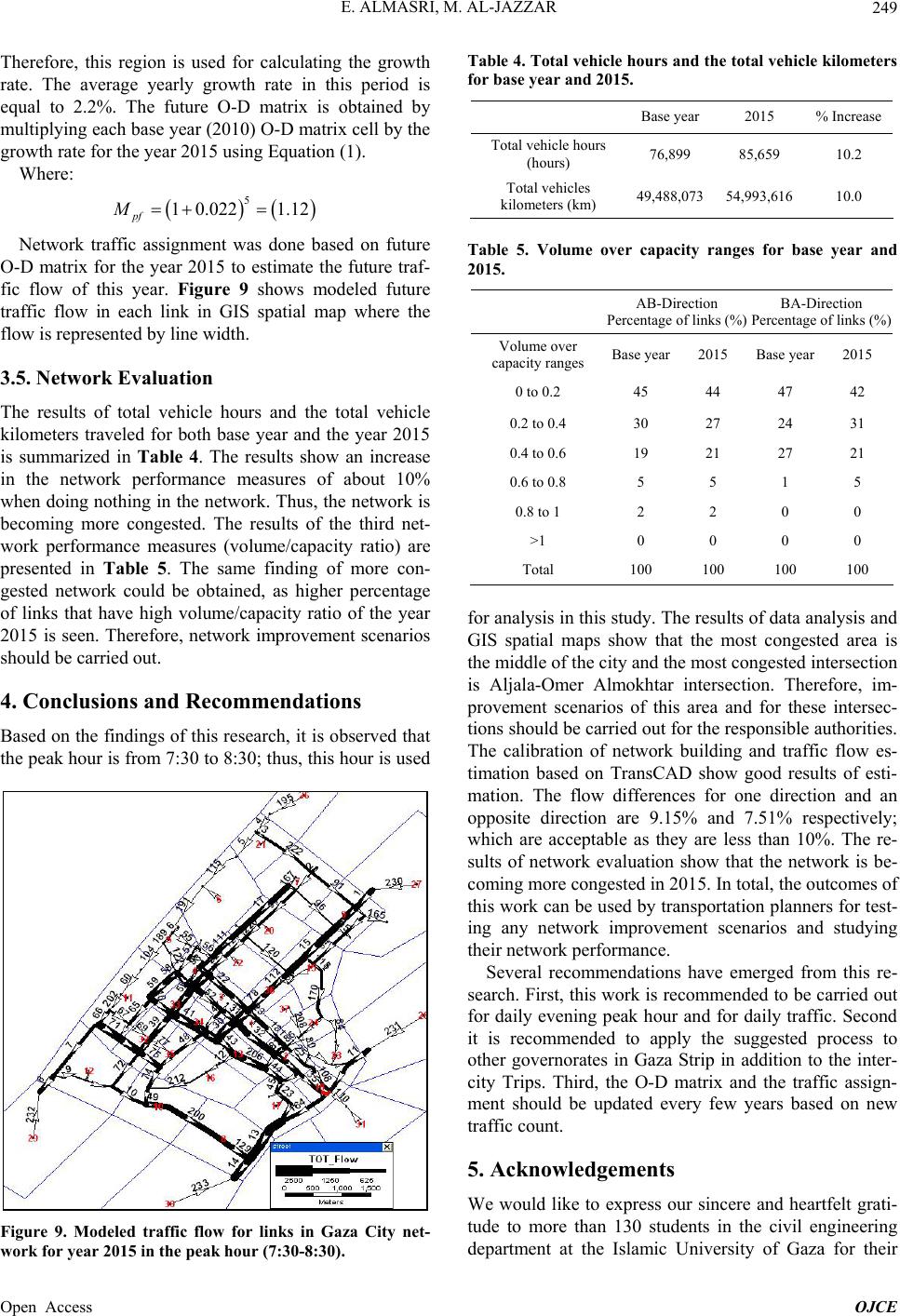 E. ALMASRI, M. AL-JAZZAR 249 Therefore, this region is used for calculating the growth rate. The average yearly growth rate in this period is equal to 2.2%. The future O-D matrix is obtained by multiplying each base year (2010) O-D matrix cell by the growth rate for the year 2015 using Equation (1). Where: 5 1 0.0221.12 pf M Network traffic assignment was done based on future O-D matrix for the year 2015 to estimate the future traf- fic flow of this year. Figure 9 shows modeled future traffic flow in each link in GIS spatial map where the flow is represented by line width. 3.5. Network Evaluation The results of total vehicle hours and the total vehicle kilometers traveled for both base year and the year 2015 is summarized in Table 4. The results show an increase in the network performance measures of about 10% when doing nothing in the network. Thus, the network is becoming more congested. The results of the third net- work performance measures (volume/capacity ratio) are presented in Table 5. The same finding of more con- gested network could be obtained, as higher percentage of links that have high volume/capacity ratio of the year 2015 is seen. Therefore, network improvement scenarios should be carried out. 4. Conclusions and Recommendations Based on the findings of this research, it is observed that the peak hour is from 7:30 to 8:30; thus, this hour is used Figure 9. Modeled traffic flow for links in Gaza City net- work for year 2015 in the peak hour (7:30-8:30). Table 4. Total vehicle hours and the total vehicle kilometers for base year and 2015. Base year 2015 % Increase Total vehicle hours (hours) 76,899 85,659 10.2 Total vehicles kilometers (km) 49,488,073 54,993,616 10.0 Table 5. Volume over capacity ranges for base year and 2015. AB-Direction Percentage of links (%) BA-Direction Percentage of links (%) Volume over capacity ranges Base year2015 Base year2015 0 to 0.2 45 44 47 42 0.2 to 0.4 30 27 24 31 0.4 to 0.6 19 21 27 21 0.6 to 0.8 5 5 1 5 0.8 to 1 2 2 0 0 >1 0 0 0 0 Total 100 100 100 100 for analysis in this study. The results of da ta analysis and GIS spatial maps show that the most congested area is the middle of the city and the most congested intersection is Aljala-Omer Almokhtar intersection. Therefore, im- provement scenarios of this area and for these intersec- tions should be carried out for the responsible authorities. The calibration of network building and traffic flow es- timation based on TransCAD show good results of esti- mation. The flow differences for one direction and an opposite direction are 9.15% and 7.51% respectively; which are acceptable as they are less than 10%. The re- sults of network evaluation show that the network is be- coming more congested in 2015. In total, the outcomes of this work can be used by transportation planners for test- ing any network improvement scenarios and studying their network performance. Several recommendations have emerged from this re- search. First, this work is recommended to be carried out for daily evening peak hour and for daily traffic. Second it is recommended to apply the suggested process to other governorates in Gaza Strip in addition to the inter- city Trips. Third, the O-D matrix and the traffic assign- ment should be updated every few years based on new traffic count. 5. Acknowledgements We would like to express our sincere and heartfelt grati- tude to more than 130 students in the civil engineering department at the Islamic University of Gaza for their Open Access OJCE  E. ALMASRI, M. AL-JAZZAR Open Access OJCE 250 help in collecting data. REFERENCES [1] Euro-Mediterranean Human Rights Network, 2013. http://www.euromedrights.org/eng/ [2] E. Almasri, “Factors Affecting Travel Choice of Shared Taxi versus Bus for Palestinian University Student Trips,” International Review of Civil Engineering, Vol. 2, No. 1, 2011, pp. 35-45. [3] Palestinian Central Bureau of Statistics, 2011. http://www.pcbs.gov.ps/site/lang__en/1/default.aspx [4] E. Almasri, “Improving Traffic Performance by Coordi- nating Traffic Signals Using Transyt-7f Model—Eljalaa Arterial Road in Gaza City as a Case Study,” Proceedings of the 4th International Engineering Conference, Gaza, 15-16 October 2012. [5] N. J. Garber and L. A. Hoel, “Traffic and Highway Engi- neering,” 4th Edition, SI Cengage Learning, USA, 2010. [6] C. A. O’Flaherty, “Traffic Planning & Engineering,” Ar- nold, London, 1997, pp. 118-128. [7] H. Bwire, “A Unified Framework for Selecting a Travel Demand Forecasting Model for Developing Countries,” Transportation Planning and Technology, Vol. 31, No. 3, 2008, pp. 347-368. http://dx.doi.org/10.1080/03081060802087809 [8] P. R. Stopher and C. G Wilmot, “Work-Trip Mode Choice Models for South Africa,” Transportation Engineering Journal of ASCE, Vol. 105, No. TE6, 1979, pp. 595-608. [9] K. Takyi, “Trip Generation Analysis in a Developing Country Context,” Transportation Research Record, 1285, pp. 9-21, 1990. [10] V. T. Arasan, M. Wermuth and B. S. Srinivas, “Model- ling of Stratified Urban Trip Distribution,” ASCE Journal of Transportation Engineering, Vol. 122, No. 5, 1996, pp. 342-349. http://dx.doi.org/10.1061/(ASCE)0733-947X(1996)122:5 (342) [11] Dar Al Handasa, “the Greater Amman Urban Transport Study,” Jordan, 1999. [12] Caliper, “TransCAD Transportation Planning Software,” 2011. http://www.caliper.com/TCTravelDemand.htm. [13] O. A. Nielsen, “A New Method for Estimating Trip Ma- trices from Counts,” Institute of Roads, Traffic and Town Planning, The Technical University of Denmark, 1993. [14] Caliper Corporation, “TransCAD 4.5 Help for Planning,” 2002. [15] J. D. D. Ortúzar and L. G. Willum, “Modeling Trans- port,” John Wiley & Sons, LTD, England, 2001. [16] K. Hamad and A. Faghri, “An Innovative Methodology for Vehicular Demand Forecasting in Developing Coun- tries,” TRB Annual Meeting, 2003. [17] R. D. Douleh, “The Use Of Traffic Assignment Model- ling Technique in Evaluating & Testing Transportation Policies and Projects Nablus City: Case Study,” Master Thesis, An-Najah National University, Nablus, 2000. |