

Paper Menu >>
Journal Menu >>
 Open Journal of Civil Engineering, 2013, 3, 234-241 Published Online December 2013 (http://www.scirp.org/journal/ojce) http://dx.doi.org/10.4236/ojce.2013.34028 Open Access OJCE Seismic Response and Stability Analysis of Single Hinged Articulated Tower Prashant Atreya1, Nazrul Islam2, Mehtab Alam1, Syed Danish Hasan3 1Department of Civil Engineering, Jamia Millia Islamia University, New Delhi, India 2Civil Engineering Department, Islamic University, Madina, KSA 3University Polytechnic, Aligarh Muslim University, Aligarh, India Email: prashant[email protected] Received November 3, 2013; revised December 3, 2013; accepted December 10, 2013 Copyright © 2013 Prashant Atreya et al. This is an open access article distributed under the Creative Commons Attribution License, which permits unrestricted use, distribution, and reproduction in any medium, provided the original work is properly cited. ABSTRACT Study of dynamic stability phenomenon in transient systems has always created interest amongst the researchers be- cause of its inherent non-linearities. Offshore structures subjected to wave, earthquake or wind loads or a combination of these loads show non-linear transient behaviour. As oceanic waves are better modelled as stochastic process, there is a need to investigate the stochastic stability of flexible offshore structures as well. Present study has been carried out to determine seismic response of Single Hinged Articulated Tower (SHAT) under different categories of wave loads and earthquake followed by its dynamic stability analysis. Different phases of wave/earthquake loading on SHAT have been explored to investigate dynamic instabilities existing during each phase. Two dimensional phase plots have been used to identify phases of dynamic instability existing within the responses of SHAT under various conditions of load- ing. Keywords: Single Hinged Articulated Tower; Earthquake; Time History; Phase Plot 1. Introduction Compliant offshore structures are favoured for deep sea water operations since they avoid unacceptably high hy- dro-dynamic loads by yielding to wave and current ac- tions leading to economic designs. These structures have large displacements with inherent non-linearities, so pre- diction of behaviour of these structures in oceanic envi- ronment is difficult and is met with many challenges. Efforts are made to use simplified realistic mathematical models to gain important insight into the response be- haviour of these structures and to explore the possibility of their dynamic instability and chaotic motion. The pres- ence of strong geometric non-linearity and non-linearity arising due to fluid structure interaction leads to the pos- sibility of dynamic instability of the systems. On account of these non-linearities, numerical investigations of com- pliant offshore structures have revealed complex behav- iour involving sub-harmonic, super-harmonic and aperi- odic solutions (Banik and others) [1-3]. Although, during last more than a decade, researchers have carried out seismic response of compliant offshore structures (Lina, H., Youngang, T. and Cong, Y.I., (2006) [4], Chandra- sekaran et al. 2008 [5]; Hasan, S.D., 2011 [6]), more efforts are required for stability analysis in non-linear environment. The stability analysis may consist of per- turbating an approximate solution. Various methods of dynamic stability analysis of non-linear system in closed form by using analytical, semi-analytical and numerical techniques have been developed (Friedmann et al., 1977 [7]; Chua and Ushida, 1981 [8]; Burton, 1982 [9], Cai, G.Q. (1995) [10], Lin, Y.K. and Cai, G.Q., 1995 [11]). Application of these techniques covers a wide range of application problems including standard problems of Van-Der-Pol oscillator, Duffing Oscillator, Double Pen- dulum etc. (Hamdan and Burton, 1993 [12]; Ravindra and Mallik, 1994 [13]; Blair et al., 1997 [14]; Yu and Bi, 1998 [15]). The main focus of application problems was to study and investigate capabilities of the methods to bring out all possible instability phenomenon latent in the system. Islam Saiful, A.B.M (2013) [16] used two di- mensional Phase Plots to determine dynamic stability phenomenon in SPAR platforms. Single Hinged Articulated Tower Platform is one of the compliant structures (Figure 1) which is economi- cally attractive especially as loading and mooring termi- 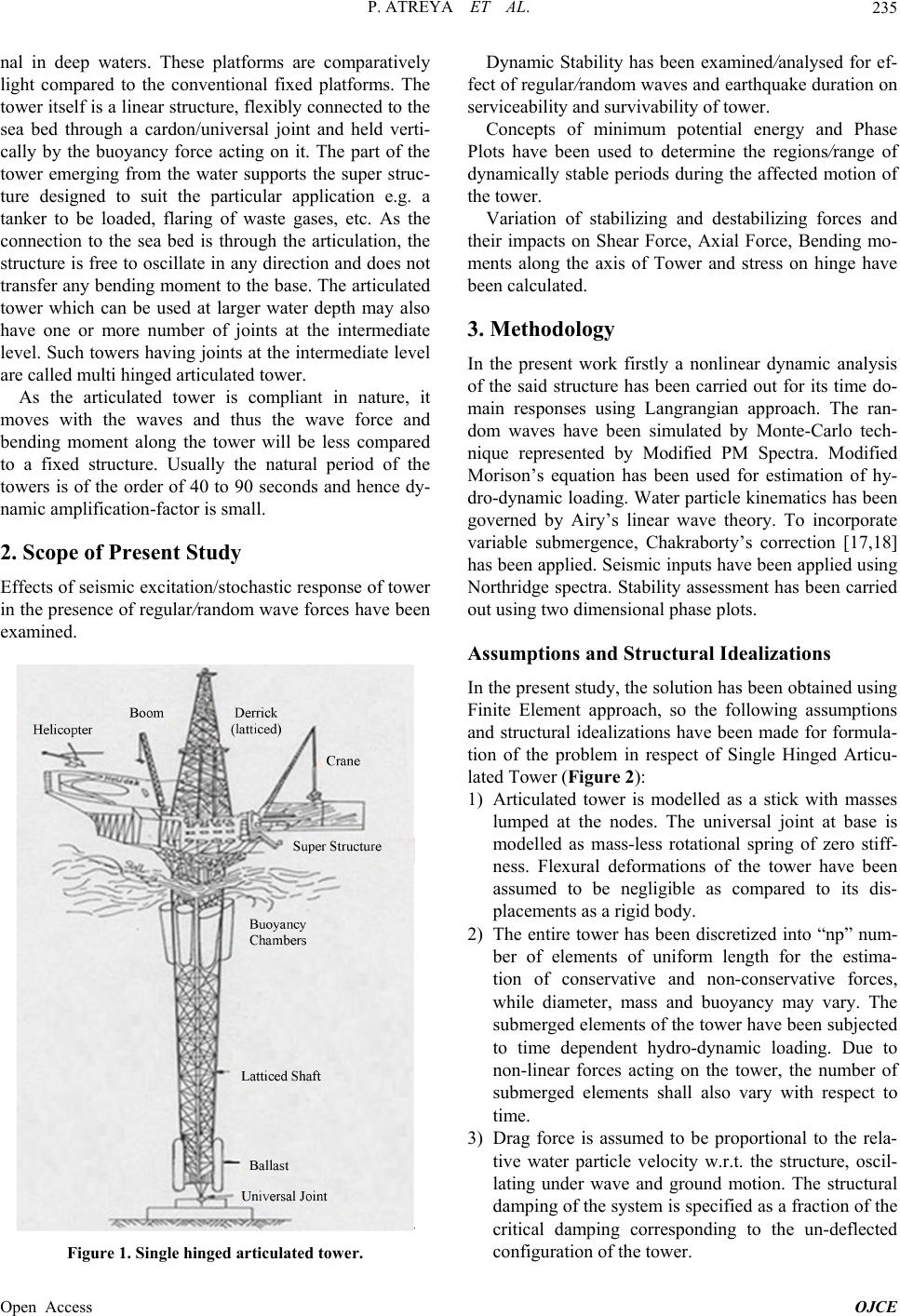 P. ATREYA ET AL. 235 nal in deep waters. These platforms are comparatively light compared to the conventional fixed platforms. The tower itself is a linear structure, flexibly connected to the sea bed through a cardon/universal joint and held verti- cally by the buoyancy force acting on it. The part of the tower emerging from the water supports the super struc- ture designed to suit the particular application e.g. a tanker to be loaded, flaring of waste gases, etc. As the connection to the sea bed is through the articulation, the structure is free to oscillate in any direction and does not transfer any bending moment to the base. The articulated tower which can be used at larger water depth may also have one or more number of joints at the intermediate level. Such towers having joints at the intermediate level are called multi hinged articulated tower. As the articulated tower is compliant in nature, it moves with the waves and thus the wave force and bending moment along the tower will be less compared to a fixed structure. Usually the natural period of the towers is of the order of 40 to 90 seconds and hence dy- namic amplification-factor is small. 2. Scope of Present Study Effects of seismic excitation/stochastic response of tower in the presence of regular/random wave forces have been examined. Figure 1. Single hinged articulated tow e r. Dynamic Stability has been examined/analysed for ef- fect of regular/random waves and earthquake duration on serviceability and survivability of tower. Concepts of minimum potential energy and Phase Plots have been used to determine the regions/range of dynamically stable periods during the affected motion of the tower. Variation of stabilizing and destabilizing forces and their impacts on Shear Force, Axial Force, Bending mo- ments along the axis of Tower and stress on hinge have been calculated. 3. Methodology In the present work firstly a nonlinear dynamic analysis of the said structure has been carried out for its time do- main responses using Langrangian approach. The ran- dom waves have been simulated by Monte-Carlo tech- nique represented by Modified PM Spectra. Modified Morison’s equation has been used for estimation of hy- dro-dynamic loading. Water particle kinematics has been governed by Airy’s linear wave theory. To incorporate variable submergence, Chakraborty’s correction [17,18] has been applied. Seismic inputs have been applied using Northridge spectra. Stability assessment has been carried out using two dimensional phase plots. Assumptions and Structural Idealizations In the present study, the solution has been obtained using Finite Element approach, so the following assumptions and structural idealizations have been made for formula- tion of the problem in respect of Single Hinged Articu- lated Tower (Figure 2): 1) Articulated tower is modelled as a stick with masses lumped at the nodes. The universal joint at base is modelled as mass-less rotational spring of zero stiff- ness. Flexural deformations of the tower have been assumed to be negligible as compared to its dis- placements as a rigid body. 2) The entire tower has been discretized into “np” num- ber of elements of uniform length for the estima- tion of conservative and non-conservative forces, while diameter, mass and buoyancy may vary. The submerged elements of the tower have been subjected to time dependent hydro-dynamic loading. Due to non-linear forces acting on the tower, the number of submerged elements shall also vary with respect to time. 3) Drag force is assumed to be proportional to the rela- tive water particle velocity w.r.t. the structure, oscil- lating under wave and ground motion. The structural damping of the system is specified as a fraction of the critical damping corresponding to the un-deflected coration of the tower. nfigu Open Access OJCE 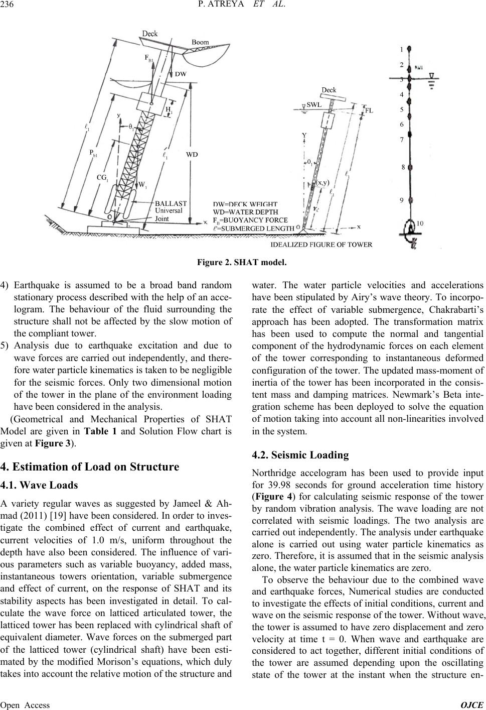 P. ATREYA ET AL. Open Access OJCE 236 Figure 2. SHAT model. 4) Earthquake is assumed to be a broad band random stationary process described with the help of an acce- logram. The behaviour of the fluid surrounding the structure shall not be affected by the slow motion of the compliant tower. 5) Analysis due to earthquake excitation and due to wave forces are carried out independently, and there- fore water particle kinematics is taken to be negligible for the seismic forces. Only two dimensional motion of the tower in the plane of the environment loading have been considered in the analysis. (Geometrical and Mechanical Properties of SHAT Model are given in Table 1 and Solution Flow chart is given at Figure 3). 4. Estimation of Load on Structure 4.1. Wave Loads A variety regular waves as suggested by Jameel & Ah- mad (2011) [19] have been considered. In order to inves- tigate the combined effect of current and earthquake, current velocities of 1.0 m/s, uniform throughout the depth have also been considered. The influence of vari- ous parameters such as variable buoyancy, added mass, instantaneous towers orientation, variable submergence and effect of current, on the response of SHAT and its stability aspects has been investigated in detail. To cal- culate the wave force on latticed articulated tower, the latticed tower has been replaced with cylindrical shaft of equivalent diameter. Wave forces on the submerged part of the latticed tower (cylindrical shaft) have been esti- mated by the modified Morison’s equations, which duly takes into account the relative motion of the structure and water. The water particle velocities and accelerations have been stipulated by Airy’s wave theory. To incorpo- rate the effect of variable submergence, Chakrabarti’s approach has been adopted. The transformation matrix has been used to compute the normal and tangential component of the hydrodynamic forces on each element of the tower corresponding to instantaneous deformed configuration of the tower. The updated mass-moment of inertia of the tower has been incorporated in the consis- tent mass and damping matrices. Newmark’s Beta inte- gration scheme has been deployed to solve the equation of motion taking into account all non-linearities involved in the system. 4.2. Seismic Loading Northridge accelogram has been used to provide input for 39.98 seconds for ground acceleration time history (Figure 4) for calculating seismic response of the tower by random vibration analysis. The wave loading are not correlated with seismic loadings. The two analysis are carried out independently. The analysis under earthquake alone is carried out using water particle kinematics as zero. Therefore, it is assumed that in the seismic analysis alone, the water particle kinematics are zero. To observe the behaviour due to the combined wave and earthquake forces, Numerical studies are conducted to investigate the effects of initial conditions, current and wave on the seismic response of the tower. Without wave, the tower is assumed to have zero displacement and zero velocity at time t = 0. When wave and earthquake are considered to act together, different initial conditions of the tower are assumed depending upon the oscillating state of the tower at the inst nt when the structure en- a 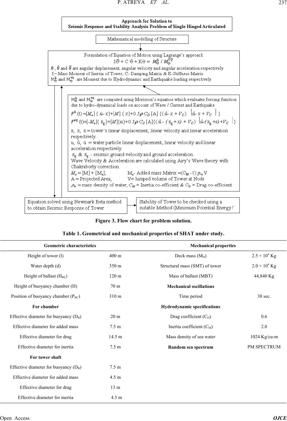 P. ATREYA ET AL. 237 Figure 3. Flow chart for problem solution. Table 1. Geometrical and mechanical properties of SHAT under study. Geometric characteristics Mechanical properties Height of tower (l) 400 m Deck mass (MD) 2.5 × 10⁶ Kg Water depth (d) 350 m Structural mass (SMT) of tower 2.0 × 10⁴ Kg Height of ballast (HBL) 120 m Mass of ballast (MBT) 44,840 Kg Height of buoyancy chamber (H) 70 m Mechanical oscillations Position of buoyancy chamber (PBC) 310 m Time period 38 sec. For chamber Hydrodynamic specifications Effective diameter for buoyancy (DB) 20 m Drag coefficient (CD) 0.6 Effective diameter for added mass 7.5 m Inertia coefficient (CM) 2.0 Effective diameter for drag 14.5 m Mass density of sea water 1024 Kg/cu-m Effective diameter for inertia 7.5 m Random sea spectrum PM SPECTRUM For tower shaft Effective diameter for buoyancy (DB) 7.5 m Effective diameter for added mass 4.5 m Effective diameter for drag 13 m Effective diameter for inertia 4.5 m Open Access OJCE  P. ATREYA ET AL. 238 Figure 4. Northridge eart hquake . counters the earthquake. Further, it is assumed that the earthquake forces act on the structure when it oscillates in a steady state under the regular sea. The responses induced due to earthquake are further compared with the responses due to strong sea-state/ waves/waves in order to establish relative severity of the two independent events. The commencement of the earthquake has been considered such that the first prom- inent peak of accelogram matches with the crest of the wave in order to get the maximum impact of wave and Earthquake load. The seismic responses of tower are further compared with the response due to strong sea states. 5. Discussion of Results on Seismic Response and Dynamic Stability Single Hinged Articulated Tower in sea exhibits non- linear behaviour because of inherent non-linearities in the system. These non-linearties are produced by non-linear excitation and restoring forces, damping non-linearity, etc. which may lead to complex response behaviour of SHAT. Non-linear restoring force is from the geometric non-linearity of the structure. Non-linear responses of the system are analysed to investigate different kinds of dy- namic instability phenomenon. During the present study, SHAT was subjected to a variety of regular wave load along with Northridge Earthquake excitation at different time. The responses are obtained in terms of heel angle rota- tion, tip displacement, shear force, bending moment, ax- ial force, base shear force, Stabilizing/Destabilizing mo- ments etc. Here, we shall discuss in details a case depict- ing behaviour of Tower under regular wave load and earthquake. The response and dynamic stability analysis has been done using Time history and two dimensional Phase Plots (Mallik, A.K. and Bhattacharjee, J.K. (2005) [20]. Strong Regular Wave (H-17.15 m, T-13.26 s) with Northridge Earthquake at 308.7 Second The analysis was performed to evaluate the response of Strong Regular Wave having wave height as 17.15 m, Time period as 13.26 sec. and Northridge Earthquake applied at 308.7 second. Wave load was initially applied at 0 second. Upto 100 seconds the motion was unstable, then due to hydrodynamic dampening, the impact of reg- ular wave on Tower got gradually reduced and the Tower motion became stable by 250 second. There after, North- ridge Earthquake was applied at 308.7 second i.e. at the crest of wave. Time history plot for Hinge angle rotation, is given at Figure 5, which provides information about magnitude of hinge angle responses generated due to Wave and Earthquake loads. The phase plots as shown from Figures 6-10 have been generated for the com- ‐1.0E‐01 ‐8.0E‐02 ‐6.0E‐02 ‐4.0E‐02 ‐2.0E‐02 0.0E+00 2.0E‐02 4.0E‐02 6.0E‐02 8.0E‐02 0100 200 300 400 500 600 700 800 TIME(sec.) ANGULARANGULARROTATION(rad.) Time HistoryforRegularWaveH‐17.15m,T‐13.26s,EQ‐HingeAngleR otation Figure 5. Time history for hinge rotation. ‐1.5E‐02 ‐1.0E‐02 ‐5.0E‐03 0.0E+00 5.0E‐03 1.0E‐02 1.5E‐02 2.0E‐02 ‐1.00E‐01‐8.00E‐02 ‐6.00E‐02 ‐4.00E‐02 ‐2.00E‐02 0.00E+002.00E‐02 4.00E‐02 6.00E‐02 8.00E‐02 PHASEPLOTFORCOMPLETEDURATIONOF2000s HEELANGLE(rad.) ANGULARVELOCITY(rad/s) HEELANGLE(rad.) ANGULARVELOCITY(rad/s) Figure 6. Phase plot for complete duration of 2000s. ‐1.2E‐02 ‐1.0E‐02 ‐8.0E‐03 ‐6.0E‐03 ‐4.0E‐03 ‐2.0E‐03 0.0E+00 2.0E‐03 4.0E‐03 6.0E‐03 8.0E‐03 ‐1.00E‐01 ‐8.00E‐02‐6.00E‐02 ‐4.00E‐02‐2.00E‐02 0.00E+002.00E‐02 4.00E‐02 6.00E‐028.00E‐02 PHASEPLOTFROM308.7to348.68sDURINGEQ HEELANGLE(rad.) ANGULARVELOCITY(rad/s) HEELANGLE(rad.) ANGULARVELOCITY(rad/s) HEELANGLE(rad.) ANGULARVELOCITY(rad/s) HEELANGLE(rad.) ANGULARVELOCITY(rad/s) Figure 7. Phase plot from 308.7 - 348.68 s during North- ridge earthquake. Open Access OJCE  P. ATREYA ET AL. 239 ‐1.0E‐02 ‐5.0E‐03 0.0E+00 5.0E‐03 1.0E‐02 1.5E‐02 ‐6.00E‐02 ‐4.00E‐02 ‐2.00E‐02 0.00E+002.00E‐02 4.00E‐02 6.00E‐0 2 PHASEPLOTFROM348.68to449sINTERVAL HEELANGLE(rad.) ANGULARVELOCITY(rad/s) HEELANGLE(rad.) ANGULARVELOCITY(rad/s) HEELANGLE(rad.) ANGULARVELOCITY(rad/s) HEELANGLE(rad.) ANGULARVELOCITY(rad/s) Figure 8. Phase plot from 348.68 to 449 s interval after Earthquake. ‐8.0E‐03 ‐6.0E‐03 ‐4.0E‐03 ‐2.0E‐03 0.0E+00 2.0E‐03 4.0E‐03 6.0E‐03 8.0E‐03 ‐2.00E‐02 ‐1.50E‐02 ‐1.00E‐02 ‐5.00E‐03 0.00E+005.00E‐03 1.00E‐02 1.50E‐02 2.00E‐02 PHASEPLOTFROM449to650sINTERVAL HEELANGLE(rad.) ANGULARVELOCITY (rad/s) HEELANGLE(rad.) ANGULARVELOCITY (rad/s) HEELANGLE(rad.) ANGULARVELOCITY (rad/s) HEELANGLE(rad.) ANGULARVELOCITY (rad/s) Figure 9. Phase plot from 449 - 650 s interval depicting sta- bilization process. ‐8.0E‐03 ‐6.0E‐03 ‐4.0E‐03 ‐2.0E‐03 0.0E+00 2.0E‐03 4.0E‐03 6.0E‐03 8.0E‐03 ‐1.50E‐02 ‐1.00E‐02‐5.00E‐03 0.00E+005.00E‐03 1.00E‐02 1.50E‐02 PHASEPLOTFROM650to2000s HEELANGLE(rad.) ANGULARVELOCITY (rad/s) HEELANGLE(rad.) ANGULARVELOCITY (rad/s) HEELANGLE(rad.) ANGULARVELOCITY (rad/s) HEELANGLE(rad.) ANGULARVELOCITY (rad/s) Figure 10. Phase plot from 650 - 2000 s duration showing Stabilized SHAT motion. plete period of 2000 seconds, from 308.7 to 348.68 sec- onds, from 348.68 to 449 seconds, from 449 to 650 sec- onds and from 650 to 2000 seconds. From phase plots, it was observed that motion from 308.7 to 348.68 seconds was under earthquake impact and showed bifurcations and chaos. During Earthquake, absolute Maximum heel angle was 5.0 degrees, which was well outside the per- mitted serviceable limits of the Tower. As the earthquake was applied for 39.98 seconds duration, after 348.68 sec- onds the hydrodynamic dampening started reducing re- sponses and trajectories started moving towards stable limit. However, from 348.68 to 449 seconds period, the motion has been non-harmonic, aperiodic and asymmet- ric. It took another 200 seconds for responses to settle down and stabilize. By 650 seconds, the responses be- came harmonic, symmetric and periodic and perfectly stable. From above discussion it is clear that with the onset of wave load, although the tower is in serviceable limits but shows slight instability for period of approx. 250 second. After onset of earthquake at 308.7 seconds it becomes unserviceable as well as unstable for a period of approximately another 350 seconds. Then it showed the stable behaviour. The hydrodynamic dampening effects are more prominent in stronger waves and the system reaches stability much early. During the entire motion, the tower has been safe due to net positive stabilizing moments acting on the tower. The Tower during initial wave period of 100 seconds can be used with some dis- comfort. Use of tower should be further avoided during Earthquake period, especially from 308.7 to 650 seconds. 6. Conclusions SHAT model was subjected to a variety of waves with and without earthquake loads. The observations for seis- mic responses and stability determination were analyzed and following conclusions have been drawn: 6.1. Conclusive Remarks on Seismic Response of SHAT 1) The initial condition described by the instant of time of the steady state tower motion at which the earth- quake strikes has significant effects on the tower re- sponse. Peak values differed upto 7% - 8% due to change in initial conditions i.e. when the earthquake is applied at axis or applied at crest of wave in regular sea. These values may further differ appreciably if earthquake occurs at the time corresponding to trough or crest of the regular wave. 2) Responses induced by earthquake in regular/random sea are further compared with the responses due to independent Strong large size wave in regular/random sea to obtain the relative severity. Hinge angle rota- tion of SHAT due to strong regular wave (H-30m, T-15 sec.) alone is 4.21 × 10⁻² radian while it in- creased to 1.43 × 10⁻¹ radian (3.39 times) when the tower is hit by only Northridge earthquake. Similarly in random sea, hinge angle rotation with only Strong large size wave (H-30m, T-15s) is 3.72 × 10⁻² radian, while it increased to 1.28 × 10⁻¹ radian (3.44 times) with small wave (H-2.15, T-4.69s) and Northridge Earthquake. This proves that even small duration earthquake gives big jolt to the structure leading to higher values of hinge angle rotation. 3) Maximum Hinge angle rotation due to small size reg- ular wave (H-2.15 m, T-4.69s) and Northridge earth- quake is 8.73 times more than that due to regular Open Access OJCE  P. ATREYA ET AL. 240 wave alone. Maximum Hinge angle rotation for large size wave (H-17.15m, T-13.26s) and earthquake is 3.17 times more than that due to regular wave. This is because larger size waves produce sufficient magni- tude of hydrodynamic dampening so as to attenuate peaks in responses. 4) The maximum tower response for Northridge earth- quake alone in regular sea has been observed to be 2.68 times more than that due to the combined load- ing of wave (H-2.15m, T-4.69s) and Northridge earthquake. This again indicates that introduction wave increases hydrodynamic dampening and thus size of peak generated due to Earthquake impact is reduced. 5) With the inclusion of the current in random/regular sea wave, there is 2.58% - 2.82% increase in Hinge angle response. 6) The absolute maximum values of Hinge angle rota- tions have been found to be in line with nature/size of waves. For each load case, values of RMS and Stan- dard Deviation for Hinge angle rotation are in the same range. 7) The base shear in case of only Northridge earthquake is 19.69 times the base shear value due to Strong large size regular wave. This shows that Base shear value in this load case has increased more rapidly as compared to increase in heel angle values. In each load case, values of RMS and Standard Deviation for Base Shear are in the same range. 8) When current is introduced in regular sea with or without Northridge Earthquake, the Maximum value of Base shear reduces. 9) For different loadings, Base Axial Force values, Mean and RMS values have common coefficient as 108. The changes in these values due to different combinations of loadings are very small. 10) Maximum bending moment due to small size regular wave (H-2.15m, T-4.69s) and Northridge earthquake is 2.46 times more than that due to regular wave alone. Maximum Bending moment for large size wave (H-17.15m, T-13.26s) and earthquake is 1.51 times more than that due to regular wave. This is because larger size waves provide hydrodynamic damping and thus reduce the seismic response. 6.2. Conclusive Remarks on Dynamic Stability Analysis of SHAT 1) During the earthquake, the tower tends to vibrate at its own natural frequency while the steady state re- sponse again takes place in wave frequency when the earthquake is over. 2) The time required to achieve the steady state response after the duration of earthquake depends upon the sea environment at that time. High sea state dampens the seismic response quickly. 3) Although short duration intensive earthquake load gives a big jolt to the tower but it survives due to in- herent restoring capacity. The responses due to short duration Earthquake die out quickly when the waves are also present. In the absence of earthquake and other environmental loads tower oscillations are checked by hydrodynamic dampening due to waves and due to tower oscillation and inherent tower buoyancy. 4) Subsequent to application of Wave/Earthquake loads, the time taken for Stabilization depends upon the na- ture/Size of the wave. The larger the size of wave, the smaller is the Stabilization period. For Small size wave (H-2.15, T-4.69s) with or without Earthquake, the time taken to achieve dynamic stability was 610 seconds. For middle sized wave (H-11.15, T-10.69s), the time taken for dynamic stability is 350 seconds. For another higher size wave (H-17.15, T-13.26s), the time taken for dynamic stability is 250 seconds. For Strong large size wave (H-30m, T-15s), the time tak- en for dynamic stability is 200 seconds. 5) When only Northridge Earthquake is applied in calm sea (with minimal size regular wave), the time taken for dynamic Stability was 1000 sec. Waves/current provide hydrodynamic dampening to the structure, in the absence of dampening the structure takes more time to stabilize. 6) With the introduction of current in wave load with or without Earthquake, the time taken for dynamic sta- bility slightly reduces which shows that the current adds up to the hydrodynamic damping effects. 7) SHAT model subjected to small regular wave (H-4.8m, T-10.4s) and 4 varieties of Earthquake loadings (1994 Northridge-NWH360, 1979 Imperial Valley H-E11140, 1979 Imperial Valley H-E13140 & 1999 Duzce, Turkey-1062-N) showed that absolute Maximum values of responses arising out of impact of all the four types of Earthquakes are having similar magnitude(except for some minor variation). North- ridge Earthquake is found to be severest of all four. The stabilization period after each earthquake is 640 sec., which once again emphasize the fact that stabi- lization period is a property of nature/size of wave. Nature of Earthquake, however governed the shape of Time History/Phase plot of responses. 8) In all the regular wave cases analysed during study, it was observed that during the initial period pertaining to onset of waves or period pertaining to Earthquake, the dynamic instability is visible in Phase plots. The motion is non-harmonic, aperiodic and asymmetric. Bifurcations are easily visible in the phase plots con- firming dynamic instability. With the passage of time, the hydrodynamic dampening effects reduce responses. Open Access OJCE  P. ATREYA ET AL. Open Access OJCE 241 The trajectories start moving towards the stable limit cycle and the motion gradually becomes harmonic, periodic and symmetric. No bifurcations are visible on the phase plots after longer duration loadings and the structure show dynamic stability. REFERENCES [1] A. K. Banik and T. K. Datta, “Stochastic Response and Stability of Single Leg Articulated Tower,” Proceeding of International Conference on Offshore Mechanics and Arctic Engineering (OMAE), Cancun, 8-13 June 2003, pp. 431-438. [2] A. K. Banik and T. K. Datta, “Stability Analysis of an Articulated Loading Platform in Regular Sea,” Journal of Computational Nonlinear Dynamics, ASME, Vol. 3, No. 1, 2009, 9 p. [3] A. K. Banik, “Dynamic Stability Analysis of Compliant Offshore Structures,” IIT, Delhi, 2004. [4] H. Lina, T. Youngang and Y. I. Cong, “Seismic Response Analysis of Articulated Tower Platform in the Still Wa- ter,” China Offshore Platform, Period 03, 2006. [5] Chandrasekaran and S. Gaurav, “Offshore Triangular TLP Earthquake Motion Analysis under Distinctly High Sea Waves,” International Journal of Ships and Offshore Structures, Vol. 3, No. 3, 2008, pp. 173-184. http://dx.doi.org/10.1080/17445300802051681 [6] S. D. Hasan, N. Islam and K. Moin, “Multi-Hinged Ar- ticulated Offshore Tower under Vertical Ground Excita- tion,” ASCE Journal of Structural Engineering, Vol. 137, No. 4, 2011, pp. 469-480. http://dx.doi.org/10.1061/(ASCE)ST.1943-541X.0000284 [7] P. Friedmann, C. E. Hammond and T.-H. Woo, “Efficient Numerical Treatment of Periodic Systems with Applica- tion to Stability Problems,” International Journal for Nu- merical Methods in Engineering, Vol. 11, No. 7, 1977, pp. 1117-1136. http://dx.doi.org/10.1002/nme.1620110708 [8] L. O. Chua and A. Ushida, “Algorithms for Comuting Al- most Periodic Steady-State Response of Nonlinear Sys- tems to Multiple Input Frequencies,” IEEE Transactions on Circuits and Systems, Vol. 28, No. 10, 1981, pp. 953- 971. http://dx.doi.org/10.1109/TCS.1981.1084921 [9] T. D. Burton, “Nonlinear Oscillator Limit Cycle Analysis Using a Finite Transformation Approach,” International Journal of Nonlinear Mechanics, Vol. 17, No. 1, 1982, pp. 7-19. http://dx.doi.org/10.1016/0020-7462(82)90033-6 [10] G. Q. Cai, “Random Vibration of Nonlinear Systems under Non-White Excitations,” Journal of Engineering Mechanics, ASCE, Vol. 121, No. 5, 1995, pp. 633-639. http://dx.doi.org/10.1061/(ASCE)0733-9399(1995)121:5( 633) [11] Y. K. Lin and G. Q. Cai, “Probabilistic Structural Dy- namics,” Advanced Theory and Mechanics, McGraw-Hill, New York, 1995. [12] M. N. Hamdan and T. D. Burton, “On the Steady State Response and Stability of Non-Linear Oscillators Using Harmonic Balance,” Journal of Sound and Vibration, Vol. 166, No. 2, 1993, pp. 255-266. http://dx.doi.org/10.1006/jsvi.1993.1295 [13] B. Rabindra and A. K. Mallik, “Stability Analysis of Non-Linearly Damped Duffing Oscillator,” Journal of Sound and Vibration, Vol. 171, No. 5, 1994, pp. 708-716. http://dx.doi.org/10.1006/jsvi.1994.1153 [14] K. B. Blair, C. M. Krousgrill and T. N. Farris, “Harmonic Balance and Continuation Techniques in the Dynamic Analysis of the Duffing’s Equation,” Journal of Sound and Vibration, Vol. 202, No. 5, 1997, pp. 717-731. http://dx.doi.org/10.1006/jsvi.1996.0863 [15] P. Yu and Q. Bi, “Analysis of Nonlinear Dynamics and Bifurcations of a Double Pendulum,” Journal of Sound and Vibration, Vol. 217, No. 4, 1998, pp. 691-736. http://dx.doi.org/10.1006/jsvi.1998.1781 [16] A. B. M. Islam Saiful, “Nonlinear Dynamic Behaviour of Fully Coupled SPAR Platform,” PhD. Thesis, University of Malaya, Kuala Lumpur, 2013. [17] S. K. Chakrabarti, “Stability Analysis of Interaction of an Articulated Tower with Waves,” Proceedings of Fluid Interaction, Heikidik i, Greece, Vol. 1, 2001, pp. 281-292. [18] S. Chakrabarti and D. Cotter, “Motion Analysis of Ar- ticulated Tower,” Journal of Waterway, Port, Coastal and Ocean Division, ASCE, Vol. 105, 1979, pp. 281-292. [19] M. Jameel and S. Ahmad, “Fatigue Reliabilitry Asses- ment of Coupled Spar-Mooring System,” Paper Pre- sented at the ASME 30th International Conference on Ocean, Offshore and Arctic Engineering (OMAE 2011- 49687), Rotterdam, 2011. [20] A. K. Mallik and J. K. Bhattacharjee, “Stability Problems in Applied Mechanics,” Narosa Publishing House, 2005. |