

Paper Menu >>
Journal Menu >>
 Open Journal of Antennas and Propagation, 2013, 1, 44-48 Published Online December 2013 (http://www.scirp.org/journal/ojapr) http://dx.doi.org/10.4236/ojapr.2013.13008 Open Access OJAPr FDTD Analysis of Millimeter Wave Binary Photon Sieve Fresnel Zone Plate I. V. Minin, O. V. Minin Siberian State Geodesy Academy, Novosibirsk, Russia. Email: [email protected] Received October 13th, 2013; revised November 14th, 2013; accepted December 9th, 2013 Copyright © 2013 I. V. Minin, O. V. Minin. This is an open access article distributed under the Creative Commons Attribution Li- cense, which permits unrestricted use, distribution, and reproduction in any medium, provided the original work is properly cited. ABSTRACT In the paper, we report about the possibilities to apply the photon sieve principle to binary diffractive lens in millimeter wave band. The FDTD simulation showing the idea of the photon sieve application to millimeter wave optics does not allow increasing the resolution power. The reason is the small number of holes in the FZP aperture. But such simulation results may be used as computational experiments of simple scale in millimeter wave allowing obtaining insight into physical systems which are characterized by nanometric objects, because the D/f and D/λ are almost the same. Keywords: Photon Sieve; Fresnel Zone Plate; FDTD Simulation; Millimeter Wave 1. Introduction According to the IEEE Standard Definition of Terms for Antennas (IEEE Std 145-1993), Fresnel lens antenna is an antenna consisted of a feed and a lens; usually Planar transmits the radiated power from the feed through the central zone and the alternate Fresnel zones of the illu- minating field on the lens. The simplest variant of Fres- nel lens is Fresnel zone plate. It is well known that Fresnel zone plates (FZP) can be used to focus and image [1,2]. But it is directly related to the width of the zone. Spatial resolution of the conven- tional diffractive lenses, such as Fresnel zone plate, is in the order of the width of the outmost zone. Therefore, reducing feature size of the zone plates helps to improve the spatial resolution. According to the zone plates theory [1,2], the width of zone from the center to the outer is decreased gradually, and especially the width of the out- ermost zone is very small. To achieve higher resolution of well-known diffractive optics, Kipp et al. proposed the novel idea of the photon sieve [3]. Photon sieves (PS) are a type of diffractive optical elements (DOEs) developed for soft X-ray focus- ing and imaging. Unlike a zone plate which is composed of concentric rings, a photon sieve is composed of a great number of pinholes suitably arranged according to the ring pattern of a classical Fresnel zone plate. It can over- come the limitations of Fresnel zone plates in the case of a big number of pinholes. For an infinite conjugate, and binary FZP of focal length f at wavelength , the radial distance to the center of the bright zone is given by [1,2]: th nn r 22 fn 2 2 n rn The width w of each zone is such the area in a paraxial approximation which is a constant (nf ), so 2n wfr . In its simplest version, the photon sieve is consisted of holes of diameter w located at a corresponding radial distance n. The holes can be distributed regularly or randomly in angle about the zone. According to the Rayleigh, the angular resolution of this PS will be di- rectly proportional to the smallest hole (largest ). r n Traditionally, if position is near the Fresnel radii, size and density of the pinholes can be used as design pa- rameters. As we know that all the photon sieves reported so far work in far-field region with macro-scale dimen- sions and their minimum hole diameter is larger than the incident wavelength r . Optical photon sieves FZP pro- vide the advantage that the size of the focused spot is not limited by the size of the smallest zone, as it is the case for traditional zone plates. FZP lenses, binary or phase correcting, have already turned into essential focusing and imaging elements and  FDTD Analysis of Millimeter Wave Binary Photon Sieve Fresnel Zone Plate 45 also in the microwave [4,5] and millimeter wave/tera- hertz systems [6-8]. The interest to PS FZP in this waveband is determined by the possibly better resolution power, light weight and simple design. But taken into account that in millimeter wave band, the number of Fresnel zones at the FZP ap- erture is small [4-8], and the effect of photon sieve to resolution power is not the evidence and has not been published in the literature yet. In this paper, we report about the possibilities to apply the photon sieve principles to diffractive lens in millime- ter wave band. 2. Calculation Experiment Technology The amplitude of the radiation passing through a specific pinhole is given by its area, the phase by its position. Positions in front of light and dark rings differ in phase by π. As a rule amplitude photon sieve FZP consisting of a large number of precisely positioned holes distributed according to an underlying Fresnel zone plate geometry, while the holes at transparent and opaque circular rings of the FZP have a π phase shift. Compared to a conven- tional photon sieve, the binary photon sieve has a trans- mission two times more amplitude PS and a diffractive efficiency approximately four times than amplitude PS. The focusing characteristics of millimeter wave PS FZP were examined by numerical experiment with the following data: diameter of PS FZP = 230 mm, = D f 150 mm, = 10 mm, the total number of zones = 8. n In this wave band the hole diameter is comparable to the incident wavelength . So in our current research, we intend to use the Finite Difference Time Domain Method (FDTD) to observe the radiation pattern characteristics of PS FZP with comparison of classical FZP [8,9]. FDTD is the method of choice for accurate and fast simulations of electromagnetic wave interaction with different structures. FDTD analyzes the propagation of electromagnetic waves in a structure by solving Max- well’s equations as a function of time at discrete loca- tions. Electromagnetic fields can be described in the differ- ential form by Maxwell equations in a linear medium as follows: Faraday’s law: BEM t AlA BdAAdl MdA t Ampere’s law: D H J t AlA DdA HdlJdA t Gauss’ law for the electric field: 0 0 A D DdA Gauss’ law for the magnetic field: 0 0 A B BdA where: E—the electric field strength; —electric induction; D H —the magnetic field strength; —magnetic induction; B A — surface; l—closed contour bounding surface 3D A ; J —current density; M —magnetization. For linear medium we can write DEB H , and are the electric permittivity and magnetic permeability of free space, respectively. First, the device under study is modeled by defining the geometry itself using 3- cells, being each cell properly characterized with its electrical conductivity, permittivity, and loss tangent [10]. Each cell is referred as a Yee cell, in honor of Kane S. Yee, who originally developed the FDTD method in 1966 [11,12]. By stacking several Yee cells, an FDTD volume can be created. The structure under study is fabricated inside this volume. The equations are solved in a leap-frog manner; that is, the electric field is solved at a given instant in time, then the magnetic field are solved at the next instant in time, and the process is repeated for the specified number of time steps [10]. D According to Yee Maxwell equations can be written as follows: Open Access OJAPr  FDTD Analysis of Millimeter Wave Binary Photon Sieve Fresnel Zone Plate 46 12, 1,12 12, 1,12 12 12 12, 1,1212, 1,12 12, 1, 12 12, 1,12 12, 1,112 12, 1,12 ,1,12 ,1,12 12 12 12 ijk ijk nn yy ijk ijk ijk ijk n xij kxi ijk ij k ij k t EE t t HH t ,1,1 ,1,12 1,1,12 source1 2,1,1 2 y nnn j kzij kzij kn ijk HH J zx 12, 12, 1 1 ,12,1 12 12 2 1 2,12,11 2,12,1 12, 12, 1 12, 12, 1 1,12,1 ,12,1 2 1,12,1 2 12, 12, 1 12 12 12 ijk ij k nn zz ijk ijk ijk ijk ij kyij k ij k ijk t EE t t H t , 12,112,1,112,, 1 source1 2,12,1 z nn nn yijkxijkxijkn ijk HH H J xy Similarly, we can write finite-difference formulas for Hx, Hy, and Hz [11,12]. Important considerations in the design of the geometry include that the ratio of the sides of the cell cannot ex- ceed two, and that the biggest cell dimension must be at least 1/20 of the highest frequency of interest. If these conditions are not met the results are not reliable [10,13]. We also successfully use FDTD methodic mentioned above for pattern reconstruction in millimeter wave me- trology [13]. The electric field intensity in our simulation was determinate according to paper [14]. 3. Simulation Results In the Figure 1 the results of PS FZP and classical FZP are shown. The red is an air, green—the dielectric with dielectric constant equal to 3. The holes were distributed randomly in angle about the zone. The holes diameters were equal to the width of correspondent Fresnel zones. The incident wave front was flat. The field intensity distribution across the focal plane is shown in the Figu re 2. The analysis of simulation results and from the Fig- ures 1 and 2 it is followed: 1) The resolution power for PS FZP and classical FZP are the same; 2) The first sidelobe level for PS FZP is about 1 dB less that for classical FZP. The gain of PS FZP is about 0.83 times less than for classical FZP. The structure of the photon sieve is based on FZP, and therefore, their behavior for the first diffraction order is similar. The main difference is that the higher-orders obtained with the FZP are reduced with the sieve. For a zone plate each ring contributes equally to the amplitude at the focus. This contribution drops abruptly to zero beyond the outermost ring which leads to strong intensity oscillations in the diffration pattern. With a photon sieve the number of pinholes per ring can be readily adjusted to yield a smooth transition which minimizes the secondary maxima. 4. Conclusions Simulation results of photon sieve FZP investigation in millimeter wave showing the resolution power of PS FZP is the same as for classical FZP. The reason is the small number of holes in the FZP aperture. But the first side lobes suppressed conveniently. So the idea of the photon sieve application to millimeter wave optics does not al- low increasing the resolution power. Another advantage of PS FZP over the FZP arises from the fabrication point of view: the PS FZP can be constructed in a single structure without any supporting substrate. But as it is known that nano-optics dealing with optical effects occurs if light interacts with matter which has artificially structured features with sizes comparable to the wavelength [15]. From this point of view, we detailed how the use of simple scale computational experiments Open Access OJAPr 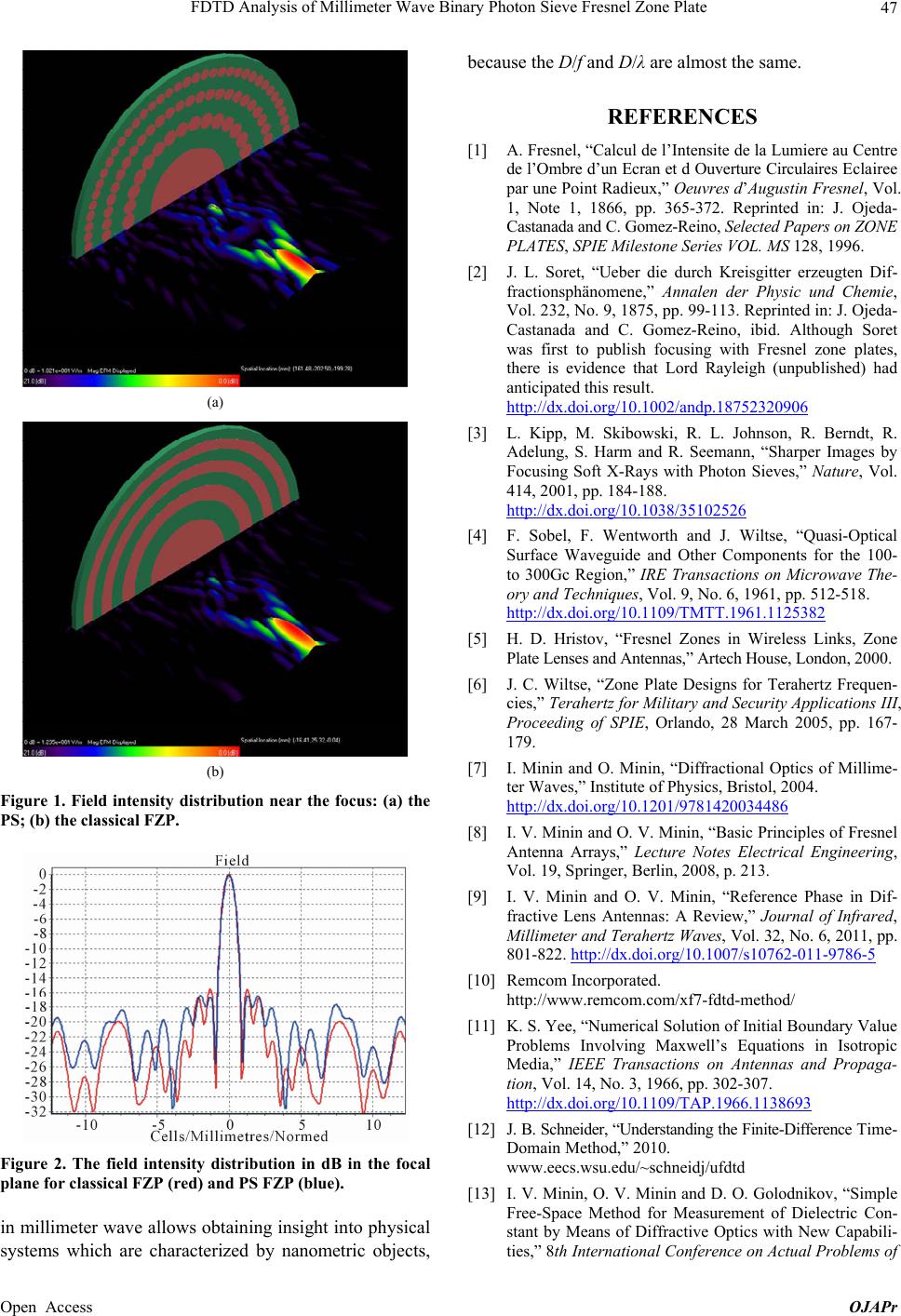 FDTD Analysis of Millimeter Wave Binary Photon Sieve Fresnel Zone Plate 47 (a) (b) Figure 1. Field intensity distribution near the focus: (a) the PS; (b) the classical FZP. Figure 2. The field intensity distribution in dB in the focal plane for classical FZP (red) and PS FZP (blue). in millimeter wave allows obtaining insight into physical systems which are characterized by nanometric objects, because the D/f and D/λ are almost the same. REFERENCES [1] A. Fresnel, “Calcul de l’Intensite de la Lumiere au Centre de l’Ombre d’un Ecran et d Ouverture Circulaires Eclairee par une Point Radieux,” Oeuvres d’Augustin Fresnel, Vol. 1, Note 1, 1866, pp. 365-372. Reprinted in: J. Ojeda- Castanada and C. Gomez-Reino, Selected Papers on ZONE PLATES, SPIE Milestone Series VOL. MS 128, 1996. [2] J. L. Soret, “Ueber die durch Kreisgitter erzeugten Dif- fractionsphänomene,” Annalen der Physic und Chemie, Vol. 232, No. 9, 1875, pp. 99-113. Reprinted in: J. Ojeda- Castanada and C. Gomez-Reino, ibid. Although Soret was first to publish focusing with Fresnel zone plates, there is evidence that Lord Rayleigh (unpublished) had anticipated this result. http://dx.doi.org/10.1002/andp.18752320906 [3] L. Kipp, M. Skibowski, R. L. Johnson, R. Berndt, R. Adelung, S. Harm and R. Seemann, “Sharper Images by Focusing Soft X-Rays with Photon Sieves,” Nature, Vol. 414, 2001, pp. 184-188. http://dx.doi.org/10.1038/35102526 [4] F. Sobel, F. Wentworth and J. Wiltse, “Quasi-Optical Surface Waveguide and Other Components for the 100- to 300Gc Region,” IRE Transactions on Microwave The- ory and Techniques, Vol. 9, No. 6, 1961, pp. 512-518. http://dx.doi.org/10.1109/TMTT.1961.1125382 [5] H. D. Hristov, “Fresnel Zones in Wireless Links, Zone Plate Lenses and Antennas,” Artech House, London, 2000. [6] J. C. Wiltse, “Zone Plate Designs for Terahertz Frequen- cies,” Terahertz for Military and Security Applications III, Proceeding of SPIE, Orlando, 28 March 2005, pp. 167- 179. [7] I. Minin and O. Minin, “Diffractional Optics of Millime- ter Waves,” Institute of Physics, Bristol, 2004. http://dx.doi.org/10.1201/9781420034486 [8] I. V. Minin and O. V. Minin, “Basic Principles of Fresnel Antenna Arrays,” Lecture Notes Electrical Engineering, Vol. 19, Springer, Berlin, 2008, p. 213. [9] I. V. Minin and O. V. Minin, “Reference Phase in Dif- fractive Lens Antennas: A Review,” Journal of Infrared, Millimeter and Terahertz Waves, Vol. 32, No. 6, 2011, pp. 801-822. http://dx.doi.org/10.1007/s10762-011-9786-5 [10] Remcom Incorporated. http://www.remcom.com/xf7-fdtd-method/ [11] K. S. Yee, “Numerical Solution of Initial Boundary Value Problems Involving Maxwell’s Equations in Isotropic Media,” IEEE Transactions on Antennas and Propaga- tion, Vol. 14, No. 3, 1966, pp. 302-307. http://dx.doi.org/10.1109/TAP.1966.1138693 [12] J. B. Schneider, “Understanding the Finite-Difference Time- Domain Method,” 2010. www.eecs.wsu.edu/~schneidj/ufdtd [13] I. V. Minin, O. V. Minin and D. О. Golodnikov, “Simple Free-Space Method for Measurement of Dielectric Con- stant by Means of Diffractive Optics with New Capabili- ties,” 8th International Conference on Actual Problems of Open Access OJAPr  FDTD Analysis of Millimeter Wave Binary Photon Sieve Fresnel Zone Plate Open Access OJAPr 48 Electronic Instrument Engineering, Novosibirsk, 26-28 September 2006, pp. 13-18. [14] S. Iwata and T. Kitamura, “Three Dimensional FDTD Analysis of Near-Field Optical Disk,” Progress in Elec- tromagnetics Research Symposium Proceedings, Marrakesh, 20-23 March 2011, pp. 157-160. [15] L. Novotny and B. Hecht, “Principles of Nano-Optics,” Cambridge University Press, Cambridge, 2006. http://dx.doi.org/10.1017/CBO9780511813535 |