

Paper Menu >>
Journal Menu >>
 Open Journal of Civil Engineering, 2013, 3, 228-233 Published Online December 2013 (http://www.scirp.org/journal/ojce) http://dx.doi.org/10.4236/ojce.2013.34027 Open Access OJCE Influence of the Elastic Modulus of the Soil and Concrete Foundation on the Displacements of a Mat Foundation Oustasse Abdoulaye Sall1*, Meissa Fall1, Yves Berthaud2, Makhaly Ba1 1Département Génie Civil, UFR SI-Université de Thiès, Thiès, Sénégal 2UFR Ingénierie, Université Pierre et Marie Curie, Paris, France Email: *[email protected] Received November 20, 2013; revised December 12, 2013; accepted December 19, 2013 Copyright © 2013 Oustasse Abdoulaye Sall et al. This is an open access article distributed under the Creative Commons Attribution License, which permits unrestricted use, distribution, and reproduction in any medium, provided the original work is properly cited. ABSTRACT In this paper, we suggest to study the behavior of a mat foundation on subsoil from the plate theory taking into account the soil-structure interaction. The objective is to highlight the soil-structure interaction particularly the influence of the rigidities of the soil and the concrete on the subgrade reaction (k) and the displacements of the mat foundation subjected to vertical loads. From plate theory and the soil-structure interaction, the general equation is reached. This equation de- pends more on the subgrade properties than the concrete foundation properties. Consequently, the behavior of the mat foundation is more influenced by soil properties than the concrete. Keywords: Mat Foundation; Plate Theory; Soil-Structure Interaction; Mechanical Properties 1. Introduction The structural and geotechnical calculations of civil en- gineering works involve the limit state method and re- quire the determination of characteristic values for resis- tance and deformation criteria of structures and soils. However, the geotechnical design is mainly based on the determination of the displacement caused by the actions applied to foundation and the determination of stresses under limit state service. The structural design is strongly based on the determination of stresses and displacements. A computational approach that takes into account struc- tural and geotechnical aspects related to the design of foundation structures must be developed. It is then ques- tion of interaction between two bodies of very different characteristics of deformability. The rupture is often fol- lowed by the formation of a thin region led in the direc- tion of contact. This area is called soil-structure interface and it is the location of the major displacements. This work focused on the foundation slab and, more particu- larly, on the characterization of the soil-structure inter- face. A precise knowledge of moduli characterizes its deformability and stress paths which should facilitate the optimization of the structural and geotechnical design of foundation. 2. Modelisation A foundation is responsible for transmitting the loads from the superstructure to the soil; it provides an inter- face between the upper part of the structure and the soil. A mat foundation is a continuous reinforced concrete slab and the study may be governed by the theory of plates whose behavior can be studied from the Lagrange equation which take into account the soil-structure inter- action. The solution of the Lagrange equation is possible with the use of the methods of Fourier series or finite differences with well-defined boundary conditions. Cha- racterization of the interface has also allowed us to see that the soil-structure interaction is important for the de- sign of foundation. Selvadurai [1] presented a detailed analysis of the soil-foundation interaction problem, ex- plaining the different approaches proposed to model this interaction. These models recognize that soil reaction is a linear function of the displacement of the soil-founda- tion interface layer. Several models have been devel- oped: Winkler model [2], Elastic continuum model [1]; Biparametric model [3]; Filonenko Borodich model [4,5]; Hetenyi model model [6]; *Corresponding author. Pasternak model [7]; 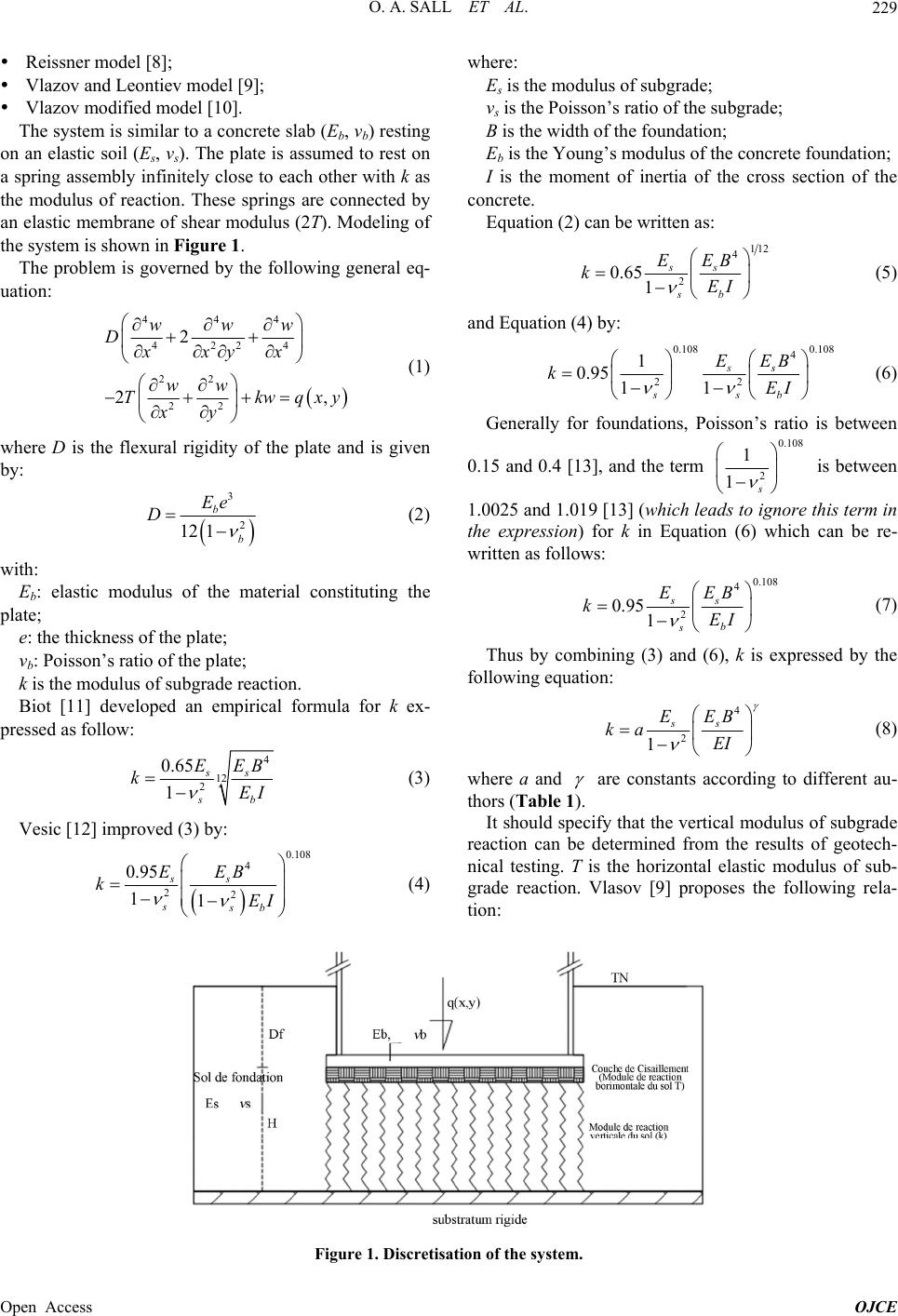 O. A. SALL ET AL. 229 Reissner model [8]; Vlazov and Leontiev model [9]; Vlazov modified model [10]. The system is similar to a concrete slab (Eb, νb) resting on an elastic soil (Es, νs). The plate is assumed to rest on a spring assembly infinitely close to each other with k as the modulus of reaction. These springs are connected by an elastic membrane of shear modulus (2T). Modeling of the system is shown in Figure 1. The problem is governed by the following general eq- uation: 444 4224 22 22 2 2, www Dxxyx ww Tkw xy qxy (1) where D is the flexural rigidity of the plate and is given by: 3 2 12 1 b b Ee D (2) with: Eb: elastic modulus of the material constituting the plate; e: the thickness of the plate; νb: Poisson’s ratio of the plate; k is the modulus of subgrade reaction. Biot [11] developed an empirical formula for k ex- pressed as follow: 4 12 2 0.65 1 ss b s EEB kEI (3) Vesic [12] improved (3) by: 0.108 4 22 0.95 11 ss ssb EEB kEI where: Es is the modulus of subgrade; νs is the Poisson’s ratio of the subgrade; B is the width of the foundation; Eb is the Young’s modulus of the concrete foundation; I is the moment of inertia of the cross section of the concrete. Equation (2) can be written as: 112 4 2 0.651 ss b s EEB kEI (5) and Equation (4) by: 0.108 0.108 4 22 1 0.95 11 ss b ss EEB kEI (6) Generally for foundations, Poisson’s ratio is between 0.15 and 0.4 [13], and the term 0.108 2 1 1s is between 1.0025 and 1.019 [13] (which leads to ignore this term in the expression) for k in Equation (6) which can be re- written as follows: 0.108 4 2 0.951 ss b s EEB kEI (7) Thus by combining (3) and (6), k is expressed by the following equation: 4 2 1 ss EEB ka EI (8) where a and are constants according to different au- thors (Table 1). It should specify that the vertical modulus of subgrade reaction can be determined from the results of geotech- nical testing. T is the horizontal elastic modulus of sub- grade reaction. Vlasov [9] proposes the following rela- tion: (4) Figure 1. Discretisation of the system. Open Access OJCE 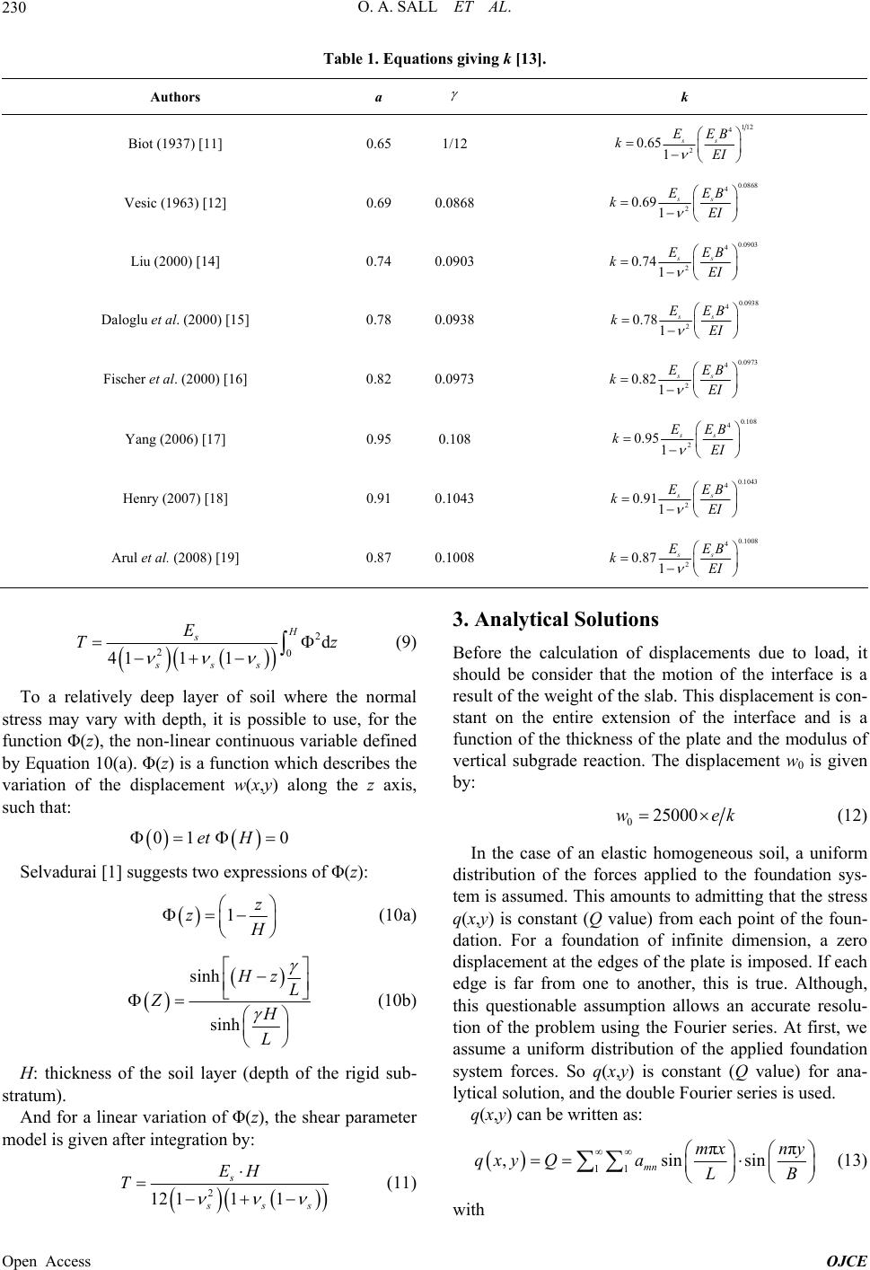 O. A. SALL ET AL. 230 Table 1. Equations giving k [13]. Authors a k Biot (1937) [11] 0.65 1/12 12 2 1 4 0.651 ss EEB kEI Vesic (1963) [12] 0.69 0.0868 0.0868 4 2 0.691 ss EEB kEI Liu (2000) [14] 0.74 0.0903 0.0903 4 2 0.741 ss EEB kEI Daloglu et al. (2000) [15] 0.78 0.0938 0.0938 4 2 0.781 ss EEB kEI Fischer et al. (2000) [16] 0.82 0.0973 0.0973 4 2 0.821 ss EEB kEI Yang (2006) [17] 0.95 0.108 0.108 4 2 0.951 ss EEB kEI Henry (2007) [18] 0.91 0.1043 0.1043 4 2 0.911 ss EEB kEI Arul et al. (2008) [19] 0.87 0.1008 0.1008 4 2 0.871 ss EEB kEI 2 20d 411 1 H s sss E T z (9) To a relatively deep layer of soil where the normal stress may vary with depth, it is possible to use, for the function Φ(z), the non-linear continuous variable defined by Equation 10(a). Φ(z) is a function which describes the variation of the displacement w(x,y) along the z axis, such that: 01 0et H Selvadurai [1] suggests two expressions of Φ(z): 1z z H (10a) sinh sinh Hz L ZH L (10b) H: thickness of the soil layer (depth of the rigid sub- stratum). And for a linear variation of Φ(z), the shear parameter model is given after integration by: 2 12 111 s sss EH T (11) 3. Analytical Solutions Before the calculation of displacements due to load, it should be consider that the motion of the interface is a result of the weight of the slab. This displacement is con- stant on the entire extension of the interface and is a function of the thickness of the plate and the modulus of vertical subgrade reaction. The displacement w0 is given by: 025000wek (12) In the case of an elastic homogeneous soil, a uniform distribution of the forces applied to the foundation sys- tem is assumed. This amounts to admitting that the stress q(x,y) is constant (Q value) from each point of the foun- dation. For a foundation of infinite dimension, a zero displacement at the edges of the plate is imposed. If each edge is far from one to another, this is true. Although, this questionable assumption allows an accurate resolu- tion of the problem using the Fourier series. At first, we assume a uniform distribution of the applied foundation system forces. So q(x,y) is constant (Q value) for ana- lytical solution, and the double Fourier series is used. q(x,y) can be written as: 11 π ,sins mn mx ny qxy QaLB π in with (13) Open Access OJCE 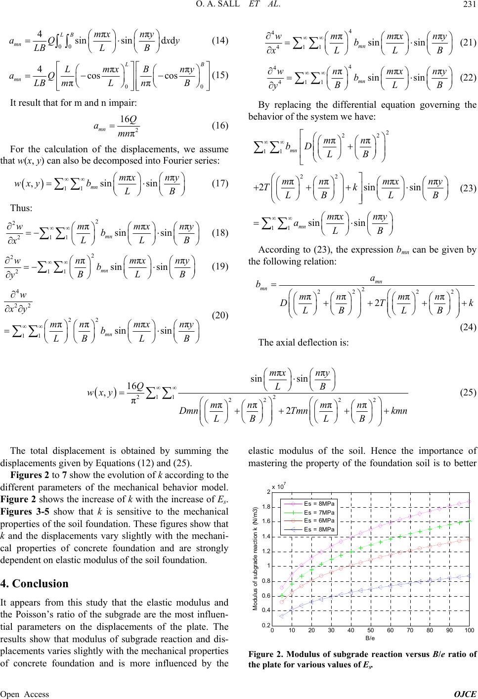 O. A. SALL ET AL. 231 00 4ππ sinsind d LB mn mx ny aQ x LBL B y (14) 00 4ππ cos cos ππ L B mn LmxBny aQ LB mLnB (15) It result that for m and n impair: 2 16Q aπ mn mn (16) For the calculation of the displacem th ents, we assume at w(x, y) can also be decomposed into Fourier series: 11 ππ ,sinsin mx ny wxyb (17 mn LB ) Thus: 2 2w 211 πππ sin sin mn mmxny b LLB x (18) 2 2 211 ππ sin sin mn wnmx b BL y πny B (19) 4 22 22 11 πππ π sin sin mn w xy m nmxny b LBL B 4 4 411 ππ sin sin mn wmmx b LL x πny B (21) 4 4 411 ππ sin sin mn wnmx b BL y πny B (22) By replacing the differential equation governing the behavior of the system we have: 2 22 11 22 11 ππ πππ π 2sin ππ sin sin mn mn mn bD LB mn mxn Tksin y L BL mx ny aLB B (23) According to (23), the expression bmn can be given by the following relation: 2 22 22 ππ ππ 2 mn mn a b mn mn DT LB LB k (20) (24) The axial deflection is: 22 11 22 22 ππ sin sin 16 ,πππ ππ 2 mx ny QLB wxy mn mn DmnTmn kmn LB LB (25) The total displacement is obtained by summing the i is study that the elastic modulus and elastic modulus of the soil. Hence the importance of d splacements given by Equations (12) and (25). Figures 2 to 7 show the evolution of k according to the different parameters of the mechanical behavior model. Figure 2 shows the increase of k with the increase of Es. Figures 3-5 show that k is sensitive to the mechanical properties of the soil foundation. These figures show that k and the displacements vary slightly with the mechani- cal properties of concrete foundation and are strongly dependent on elastic modulus of the soil foundation. 4. Conclusion It appears from th the Poisson’s ratio of the subgrade are the most influen- tial parameters on the displacements of the plate. The results show that modulus of subgrade reaction and dis- placements varies slightly with the mechanical properties of concrete foundation and is more influenced by the mastering the property of the foundation soil is to better 01020 3040 5060708090100 0.2 0.4 0.6 0.8 1 1.2 1.4 1.6 1.8 2x 10 7 B/e Mod ulus of subgrade react i on k (N/ m 3) Es = 8MPa Es = 7MPa Es = 6MPa Es = 8MPa Figure 2. Modulus of subgrade reaction versus B/e ratio of the plate for various values of Es. Open Access OJCE 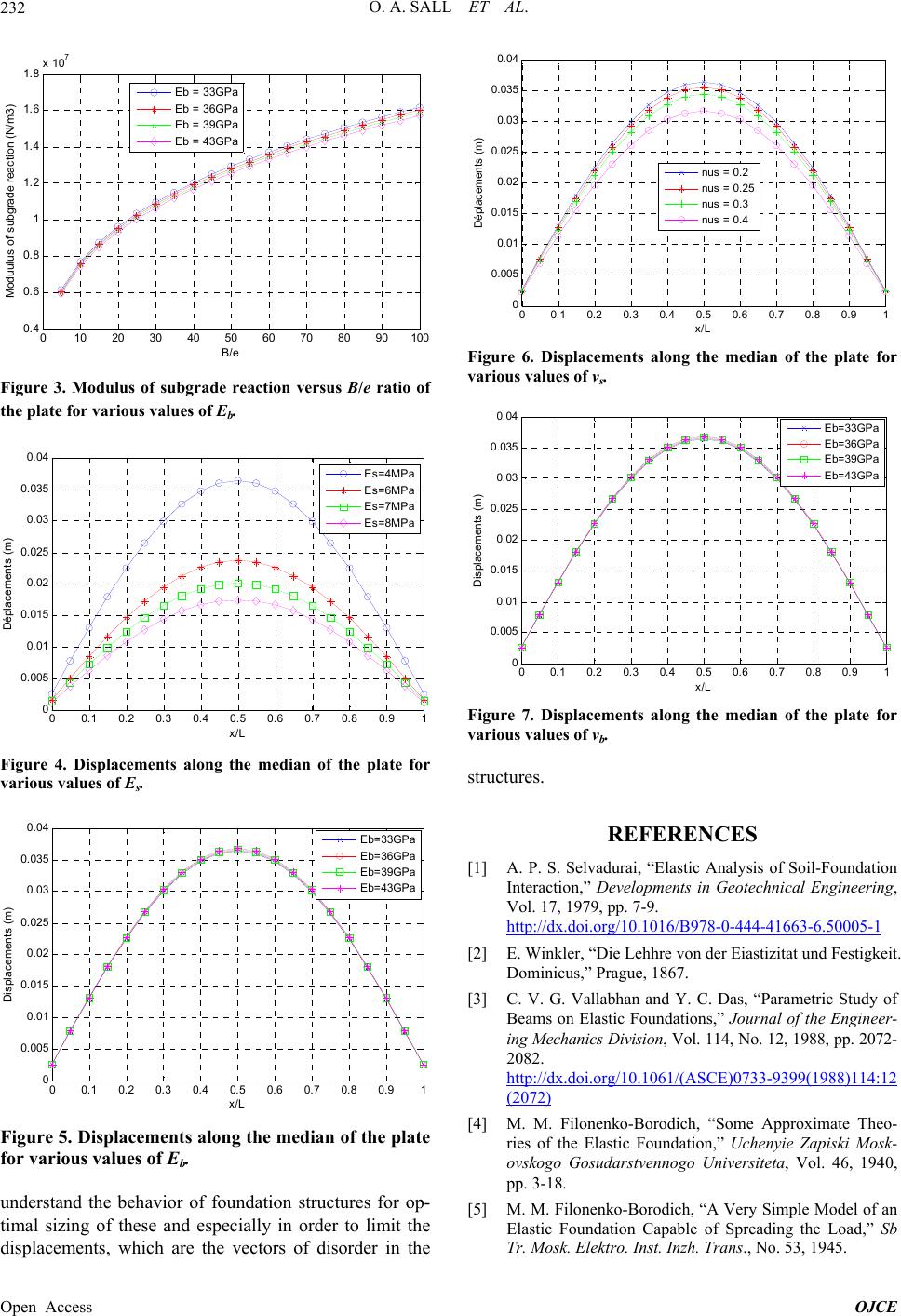 O. A. SALL ET AL. 232 010 20 30 40 50 60 7080 90100 0. 4 0. 6 0. 8 1 1. 2 1. 4 1. 6 1.8 x 10 7 B/e Moduul us of subgrade reacti on (N/ m3) Eb = 33GP a Eb = 36GP a Eb = 39GP a Eb = 43GP a Figure 3. Modulus of subgrade reaction versus B/e ratio of the plate for various values of Eb. 00.1 0.2 0.3 0.4 0.5 0.6 0.7 0.8 0.91 0 0. 005 0. 01 0. 015 0. 02 0. 025 0. 03 0. 035 0. 04 x/L Déplacemen ts (m) Es=4MPa Es=6MPa Es=7MPa Es=8MPa Figure 4. Displacements along the median of the plate for arious values of Es. v 00.1 0.2 0.3 0.4 0.5 0.6 0.7 0.8 0.9 1 0 0. 005 0.01 0. 015 0.02 0. 025 0.03 0. 035 0.04 x/L Displacements (m) Eb=33GPa Eb=36GPa Eb=39GPa Eb=43GPa Figure 5. Displacements along the median of the plate r various values of Eb. understand the behavior of foundation structures for op- timal sizing of these and especially in order to limit the displacements, which are the vectors of disorder in the fo 00.1 0.2 0.3 0.4 0.5 0.6 0.7 0.8 0.91 0 0. 005 0. 01 0. 015 0. 02 0. 025 0. 03 0. 035 0. 04 x/L Déplacem ents (m ) nus = 0.2 nus = 0.25 nus = 0.3 nus = 0.4 Figure 6. Displacements along the median of the plate fo various values of νs. r 00.1 0.2 0.3 0.4 0.5 0.6 0.7 0.8 0.91 0 0. 005 0. 01 0. 015 0. 02 0. 025 0. 04 0. 03 0. 035 x/L Displacements (m ) Eb=33GPa Eb=36GPa Eb=39GPa Eb=43GPa Figure 7. Displacements along the median of the plate for various values of νb. structures. RENCES [1] A. P. S. Selvadurai, “Elastic Analysis of Soil-Foundation Interaction,” Developments in Geotechnical Engineering, Vol. 17, 1979, pp. 7-9. http://dx.doi.org/10.1016/B978-0-444-41663-6.50005-1 REFE [2] E. Winkler, “Die Lehhre von der Eiastizitat und Festigkeit. Dominicus,” Prague, 1867. [3] C. V. G. Vallabhan and Y. C. Das, “Parametric Study of Beams on Elastic Foundations,” Journal of the Engineer- ing Mechanics Division, Vol. 114, No. 12, 1988, pp. 2072- 2082. http://dx.doi.org/10.1061/(ASCE)0733-9399(1988)114:12 (2072) [4] M. M. Filonenko-Borodich, “Some Approximate Theo lonenko-Borodich, “A Very Simple Model of an oundation Capable of Spreading the Load,” Sb Tr. Mosk. Elektro. Inst. Inzh. Trans., No. 53, 1945. - - ries of the Elastic Foundation,” Uchenyie Zapiski Mosk ovskogo Gosudarstvennogo Universiteta, Vol. 46, 1940, pp. 3-18. [5] M. M. Fi Elastic F Open Access OJCE 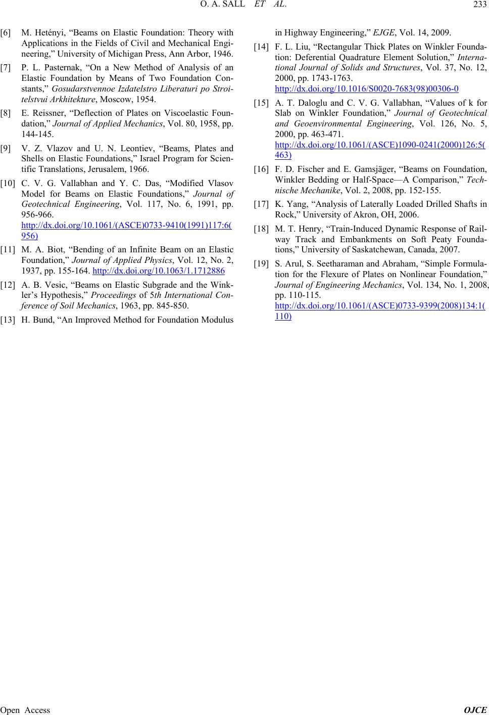 O. A. SALL ET AL. Open Access OJCE 233 [6] M. Hetényi, “ation: Theory with Applications i Mechanical Engi- - - Plates on Viscoelastic Foun- oi.org/10.1061/(ASCE)0733-9410(1991)117:6( Beams on Elastic Found n the Fields of Civil and neering,” University of Michigan Press, Ann Arbor, 1946. [7] P. L. Pasternak, “On a New Method of Analysis of an Elastic Foundation by Means of Two Foundation Con stants,” Gosudarstvennoe Izdatelstro Liberaturi po Stroi telstvui Arkhitekture, Moscow, 1954. [8] E. Reissner, “Deflection of dation,” Journal of Applied Mechanics, Vol. 80, 1958, pp. 144-145. [9] V. Z. Vlazov and U. N. Leontiev, “Beams, Plates and Shells on Elastic Foundations,” Israel Program for Scien- tific Translations, Jerusalem, 1966. C. V. G[10] . Vallabhan and Y. C. Das, “Modified Vlasov Model for Beams on Elastic Foundations,” Journal of Geotechnical Engineering, Vol. 117, No. 6, 1991, pp. 956-966. http://dx.d 956) [11] M. A. Biot, “Bending of an Infinite Beam on an Elastic Foundation,” Journal of Applied Physics, Vol. 12, No. 2, 1937, pp. 155-164. http://dx.doi.org/10.1063/1.1712886 [12] A. B. Vesic, “Beams on Elastic Subgrade and the Wink- ler’s Hypothesis,” Proceedings of 5th International Con- ference of Soil Mechanics, 1963, pp. 845-850. [13] H. Bund, “An Improved Method for Foundation Modulus in Highway [14] F. L. Liu, “Rectangular Thick Plates on Winkler Founda- tion: D Engineering,” EJGE, Vol. 14, 2009. eferential Quadrature Element Solution,” Interna- tional Journal of Solids and Structures, Vol. 37, No. 12, 2000, pp. 1743-1763. http://dx.doi.org/10.1016/S0020-7683(98)00306-0 [15] A. T. Daloglu and C. V. G. Vallabhan, “Values of k for Slab on Winkler Foundation,” Journal of Geotechnical and Geoenvironmental Engineering, Vol. 126, No. 5, 2000, pp. 463-471. http://dx.doi.org/10.1061/(ASCE)1090-0241(2000)126:5( 463) [16] F. D. Fischer and E. Gamsjäger, “Beams on Foundation, Winkler Bedding or Half-Space—A Comparison,” Tech- nische Mechanike, Vol. 2, 2008, pp. 152-155. [17] K. Yang, “Analysis of Laterally Loaded Drilled Shafts in askatchewan, Canada, 2007. r the Flexure of Plates on Nonlinear Foundation,” 08)134:1( Rock,” University of Akron, OH, 2006. [18] M. T. Henry, “Train-Induced Dynamic Response of Rail- way Track and Embankments on Soft Peaty Founda- tions,” University of S [19] S. Arul, S. Seetharaman and Abraham, “Simple Formula- tion fo Journal of Engineering Mechanics, Vol. 134, No. 1, 2008, pp. 110-115. http://dx.doi.org/10.1061/(ASCE)0733-9399(20 110) |