

Paper Menu >>
Journal Menu >>
 Journal of Power and Energy Engineering, 2013, 1, 95-100 http://dx.doi.org/10.4236/jpee.2013.15016 Published Online October 2013 (http://www.scirp.org/journal/jpee) Copyright © 2013 SciRes. JPEE 95 Performance Investi gation of Membrane Elec trode Assemblies for High Tem perature Proton Exchange Membrane Fu el C el l Huaneng Su, Sivakumar Pasupathi, Bernard Bladergroen, Vladimir Linkov, Bruno G. Pollet HySA Systems Competence Centre, South African Institute for Advanced Materials Chemistry, University of the Western Cape, Private Bag X17, Bellville 7535, South Africa. Email: [email protected] Received August 2013 ABSTRACT Different types of ABPBI (poly(2,5-benzimidazole)) membranes and polymer binders were evaluated to investigate the performance of MEAs for high temperature proton exchange membrane fuel cell (HT-PEMFC). The properties of the prepared MEAs were evaluated and analyzed by polarization curve, electrochemistry impedance spectroscopy (EIS), cyclic voltammetry (CV) and durability test. Th e results showed that MEA with modified ABPBI membrane (AM) has satisfactory performance and durability for fuel cell application. Compare to conventional PBI or Nafion binders, poly- tetrafluoroethylene (PTFE) and polyvinylidene difluoride (PVDF) are more attractive as binders in the catalyst layer (CL) of gas diffusion electrode (GDE) for HT-PEMFC. Keywords: High Temperature Proton Exchange Membrane Fuel Cell; ABPBI (Poly(2,5-Benzimidazole)); Polymer Binders; Gas Diffusion Electrode; Membrane Electrode Assembly 1. Introduction Polybenzimidazole (PBI) based high temperature proton exchange membrane fuel cells (HT-PEMFCs) have at- tracted more and more attention in these years due to their advantages over low temperature PEMFCs based on perfluorosulphonic acid polymer electrolytes ( e.g. Nafion) [1]. However, the sluggish kinetics of the oxygen reduc- tion reaction (ORR) [2] and the transport limitations of protons and reactants in cathode, especially in the pres- ence of phosphoric acid (PA), limit the cell performance of the high temperature PEMFC. Therefore, enhancing the cell performance is one of the most important issues for high temperature PEMFC being more widely consi- dered as an alternative to the low temperature PEMFC systems. Membrane electrode assembly (MEA) is the most im- portant component in high temperature PEMFC system and it plays a major role in determining cell performance. It consists of a proton exchange membrane sandwiched between two gas diffusion electrodes (GDEs), which pos- sess a porous structure that allows easy transport of reac- tant gases and water to and from the catalytically active zone. Therefore, the components of MEA, i.e. electrolyte membrane and GDEs, have significant influence on the performance of high temperature PEMFC. Several types of electrolyte membrane, such as poly [2,2’-(m-phenylene)-5,5’-bibenzimidazole (PBI or mPBI), poly(2,5-benzimidazole) (ABPBI) and their derivatives [3]; several types of polymer ionomers, such as PBI [4-6], polytetrafluoroethylene (PTFE) [7,8], polyvinylidene dif- luoride (PVDF) [9,10] and Nafion [11,12], can be used in the MEA as proton exchange membranes and catalyst layer (CL) binders for high temperature PEMFC. The phy- sicochemical properties of these membranes and binders are different from each other; consequently the resultant MEAs have their own advantages and shortcomings. In this work, the MEAs with four types of ABPBI mem- branes and four types of binders were investigated to evaluate their fuel cell performances. The properties of these MEA were characterized by single cell polarization, electrochemical analysis and dur ability test. 2. Experimental 2.1. Preparation of GDEs Hispec 4000 Pt/C catalyst (40 wt% Pt, Johnson Matthey) was used in this study. All GDEs were prepared by our newly developed spraying method [13]. The catalyst powd- ers were deposited onto the microporous layer of com- mercially available GDL (Freudenberg, Germany). The 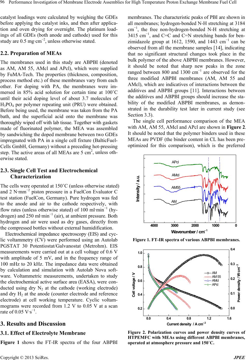 Performance Investigation of Membrane Electrode Assemblies for High Temperature Proton Exchange Membrane Fuel Cell Copyright © 2013 SciRes. JPEE 96 catalyst loadings were calculated by weighing the GDEs before applying the catalyst inks, and then after applica- tion and oven drying for overnight. The platinum load- ings of all GDEs (both anode and cathode) used for this study are 0.5 mg∙cm−2, unless otherwise stated. 2.2. Preparation of MEAs The membranes used in this study are ABPBI (denoted as AM, AM 55, AMcl and APcl), which were supplied by FuMA-Tech. The properties (thickness, composition, process method etc.) of these membranes vary from each other. For doping with PA, the membranes were im- mersed in 85% acid solution for certain time at 100˚C until their acid doping level of about 3.7 molecules of H3PO4 per polymer repeating unit (PRU) were obtained. Before being used, the membrane was taken from the PA bath, and the superficial acid onto the membrane was thoroughly wiped off with lab tissue. To ge the r w ith gaskets made of fluorinated polymer, the MEA was assembled by sandwiching the doped membrane between two GDEs impregnated with PA in a single cell fixture (BalticFuel- Cells GmbH, Germany) without a preceding hot-pressing step. The active areas of all MEAs are 5 cm2, unless oth- erwise stated. 2.3. Single Cell Test and Electrochemical Characteriz ation The cells were operated at 150˚C (unless otherwise stated) and 2 N∙mm−2 piston pressure in a FuelCon Evaluator C test station (FuelCon, Germany). Pure hydrogen was fed to the anode and air to the cathode respectively, with flow rates (unless otherwise stated) of 100 ml∙min−1 (hy- drogen) and 250 ml∙min−1 (air), at ambient pressure. Both hydrogen and air were used as dry gases, directly from the compressed bottles without external humidification. Electrochemical impedance spectroscopy (EIS) and cyc- lic voltammetry (CV) were performed using an Autolab PGSTAT 30 Potentiostat/Galvanostat (Metrohm). EIS measurements were carried out at a cell voltage of 0.6 V with amplitude of 5 mV, and in the frequency range of 100 mHz to 20 kHz. The impedance data were obtained by calculation and simulation with Autolab Nova soft- ware. Voltammetric measurements, undertaken to study the electrochemical active surface area (EASA), were con- ducted using dry N2 at the cathode (working electrode) and dry H2 at the anode (counter electrode and reference electrode) at cell working temperature. Cyclic voltam- mograms were recorded from 1.2 V to 0.05 V at a scan rate of 0.05 V∙s−1. 3. Results and Discussion 3.1. Effect of Electrolyte Membrane Figure 1 shows the FT-IR spectra of the four ABPBI membranes. The characteristic peaks of PBI are shown in all membranes; hydrogen-bonded N-H stretching at 3184 cm−1, the free non-hydrogen-bonded N-H stretching at 3415 cm−1, and C=C and C=N stretching bands for ben- zimidazole group at 1612, 1590, and 1443 cm−1 can be observed from all the membrane samples [14], indicating that no significant structural changes took place in the bulk polymer of the above ABPBI membranes. However, it should be noted that sharp new peaks in the zone ranged between 800 and 1300 cm−1 are observed for the three modified ABPBI membranes (AM, AM 55 and AMcl), which are indicatives of interactions between the additives and ABPBI groups [11]. Interactions between the additives and ABPBI groups should increase the sta- bility of the modified ABPBI membranes, as demon- strated in the durability test later in current study (see Section 3.3). The single cell performance comparison of the MEA with AM, AM 55, AMcl and APcl are shown in Figure 2. It should be noted that the polymer binders used in these MEAs are PVDF (the binder content in CL has been pre- optimized for this comparison), which is the preferred 4000 3000 2000 10000 Intensity / a.u. W avenum b er / cm − 1 AM AM5 5 AMc l APcl Figure 1. FT-IR spectra of various ABPBI membranes. 0.0 0.4 0.8 1.2 1.6 0.2 0.4 0.6 0.8 1.0 AM AM 55 AMcl APcl Current density / A cm − 2 Cell voltage / V 0.0 0.1 0.2 0.3 0.4 P ower density / W cm − 2 Figure 2. Polarization curves and power density curves of HTPEMFC with MEAs using different ABPBI membranes, operated at atmosphere pressure and 150˚C.  Performance Investigation of Membrane Electrode Assemblies for High Temperature Proton Exchange Membrane Fuel Cell Copyright © 2013 SciRes. JPEE 97 binder pre-optimized in Section 3.2. It is clear that the MEA prepared by AM membrane yields much better per- formance than the MEA prepared with other membranes. At a working voltage of 0.6 V, the current density of the MEA with AM membrane reaches 0.208 A∙cm−2, the maximum power density of the MEA with GDE-1 can reach 0.363 W∙cm−2 at 0.313 V. To understand the performance difference of the MEAs prepared with these membranes, overall analysis on the polarization curves and electrochemical measurements on both GDEs are performed. Generally, the po larization curve of a PEMFC could be divided into three segments (corresponding to different electrochemical processes) ac- cording to its different voltage drop rates. The initial drop of the curve at a very low current density is due to the sluggish kinetics of oxygen reduction at the cathode, determined by the nature of the electrodes. It can be seen in Figure 2 that all MEAs show similar voltage drop in this region (0 - 0.1 A cm–2), which is reasonable consi- dering the GDEs used in all MEAs were the same. To prove this point, CV measurements are performed to study the EASAs of the all MEAs, as shown in Figure 3 (only H2 desorption peaks were showed for clarity). The corresponding EASAs were calculated from the H2 desorption peak of each voltammogram and the re- sults are summarized in Table 1. It can be seen that the EASA values of all MEAs are between 17.4 and 22.3 m2∙g−1, only small differences were detected among these MEAs. The EASA results are certainly consistent with their performances (activation polarization zone) pre- sented in Figure 2. Figure 3. Cyclic voltammograms of the MEAs with differ- ent ABPBI membranes. Table 1. Electrochemical characteristics of the MEAs with different ABPBI membranes. MEA type RΩ (Ω) Rct (Ω) EASA (m2∙g−1) AM 0.05 0.07 22.3 AM 55 0.12 0.13 17.4 AMcl 0.13 0.11 18.7 APcl 0.12 0.13 19.1 The subsequent drop in the polarization curve is as- cribed to ohmic loss, which originates from ionic flow through the electrolyte membrane, and from electron flow through the electrode layers, current collectors and flow field plates. As shown in Figure 2, the four MEAs present much different decreasing slopes in the linear region, implying that they had different ohmic resis- tances. To verify the resistances of the single cells with these MEAs, in situ impedance measurements are per- formed at the cell voltage of 0.6 V, as shown in Figure 4. Only one semicircular loop can be observed in the Ny- quist plot as the electrode process is dominated by ORR [15]. Through simulation with a simple RC equivalent circuit, their corresponding cell resistances (RΩ) and charge transfer resistances (Rct) can be calculated, which are also presented in Table 1. It can be seen that there is no sig- nificant difference in cell ohmic resistance for the MEAs with the last three membranes (i.e. AM 55, AMcl and APcl), which is consistent with the similar decreasing slopes in the linear regions of their polarization curves presented in Figure 2. However the ohmic resistance of the MEA with AM membrane is only 0.05 Ω, less than half of the other membranes. It suggests that AM mem- brane has higher proton conductivity than other mem- branes because all other parts in the test fixture during testing were identical. Moreover, the charge transfer re- sistance of the AM MEA is much smaller than those of the other three, which suggests that AM MEA yielded a more efficient electrochemical active layer, which means that the interactions between the GDE and the AM mem- brane are more efficient. The last voltage drop at high current density is due to mass transport limitations o ccurring in the electrodes and the membrane. However, from Figure 2 it can be seen that, for all MEAs, the vo ltage drop rates in low cell vo l- tage region (<0.4 V) of their polarization curves are al- most the same with that in their linear regions, which means that no obvious mass transfer limitations in these Figure 4. In situ impedance curves of the MEAs with dif- ferent membranes, at a cell voltage of 0.6 V. 0.05 0.10 0.15 0.20 0.25 -0.02 0.00 0.02 0.04 0.06 AM AM 55 AMcl APcl − Z' ' / Ω Z' / Ω  Performance Investigation of Membrane Electrode Assemblies for High Temperature Proton Exchange Membrane Fuel Cell Copyright © 2013 SciRes. JPEE 98 MEAs even at the high current densities. It is unders- tandable when considering the high operating tempera- ture (150˚C, only water vapor existed in the GDEs) and the high stoichiometries reactants (ca. 7/7.5 for H2/A ir at 0.4 A∙cm–2) due to the small active area (~5 cm2) even at low gases flow rates [16]. From all these analyses and electrochemical results, it can be concluded that the good performance of the MEA with AM membrane is primarily attributable to the high- er proton conductivity and good interactivity of the elec- trolyte membrane and the GDEs, which makes a more efficient electrochemical active layer, accordingly the minor ohmic resistance and charge transfer resistance. For these reasons, the AM membrane, which performed best at usual working voltage of 0.6 V and maximum power density, is chose for all subsequent studies. 3.2. Effect of Polymer Binders Figure 5 shows the performance comparison of the MEA with the four different polymer binders. It is clear that the PTFE and PVDF GDEs yield much better performance than the GDEs prepared with PBI and Nafion binders in all regions of the polarization curve. At a working vol- tage of 0.6 V, the current density of the MEA with PVDF GDEs reaches 0.53 A∙cm−2, 121% higher than that (0.24 A∙cm−2) of the MEA with PBI GDEs. The maximum power density of the MEA with PTFE GDEs can reach 0.61 W∙cm−2 at 0.35 V. These values are almost the best results yet reported for similar PA-doped PBI fuel cell and operated using air, which are comparable to the per- formances of the commercial MEAs with high Pt load- ings [17]. This is mainly attribut able to the properties of PTFE and PVDF binders that they exist in the CLs as a fiber phase, which makes catalyst particles less likely to be encapsulated in the binder, then making more Pt sur- face available in the CLs. On the contrary, PBI and Na- fion polymer ionomers are easily covered on the surface of the catalyst particles, which could impose mass trans- port limitation in CLs due to the low gas permeability of these films formed on the catalyst sites [15]. 3.3. Durability From above physical characterizations and electrochem- ical analysis results, it can be concluded that good MEA performance (at usual working voltage of 0.6 V) can be delivered by using PVDF as CL binder and AM mem- brane as electrolyte membrane. However, the stability or durability of this MEA is also a major concern for the real application and commercialization of HT-PEMFC. The remarkable long term stability of PA-doped PBI MEA is achieved in some research groups’ works [9, 10,18,19]. To verify the stabilities of the MEA with AM membrane and PVDF binder, a short term durability test was performed, as shown in Figure 6. 0.0 0.5 1.0 1.5 2.0 2.5 0. 2 0. 4 0. 6 0. 8 1. 0 PVDF PTFE PBI Nafion Cell voltage / V Current density / A cm − 2 Figure 5. Polarization curves of PA-doped ABPBI (AM membrane) fuel cell using GDEs prepared with different polymer binders, operated with flow rates of 200 ml∙min−1 (hydrogen) and 1000 ml∙min−1 (air), at ambient pressure and 160˚C. Figure 6. The durability test of the MEA with AM mem- brane and PVDF binder. It can be seen that the cell voltage of the MEA remains at ~0.56 V without obvious drop after almost 1000 h op- eration. The degradation rate calculated by linear fitting of cell voltage data points after the MEA activation is about 56.8 μV∙h–1, which are acceptable for most appli- cations [12,18-20]. 4. Conclusion Four types of ABPBI membranes and four types of po- lymer binders were evaluated to investigate the perfor- mance of MEAs for high temperature proton exchange membrane fuel cell (HT-PEMFC). The results showed that MEA with modified ABPBI membrane (AM) as electrolyte and PVDF as CL binder has satisfactory per- formance and durability for fu e l cell ap plication. At usual working voltage of 0.6 V and cell temperature of 150˚C, the peak power density reached 0.363 W∙cm−2, and the current density at usual working voltage 0.6 V was up to  Performance Investigation of Membrane Electrode Assemblies for High Temperature Proton Exchange Membrane Fuel Cell Copyright © 2013 SciRes. JPEE 99 0.208 A∙cm−2, which are comparable to the results yet reported for similar MEAs with Pt loading of ~0.5 mg∙cm−2. The MEA showed good durability in a short term operation: the cell voltage remained at ~0.56 V without obvious drop after almost 1000 h operation. 5. Acknowledgements This work is supported by Hydrogen and Fuel Cell Technologies RDI Programme (HySA), funded by the Dep artment of Science and Technology in South Africa (project KP 1-S01). REFERENCES [1] J. Zhang, Z. Xie, J. Zhang, Y. Tang, C. Song, T. Navessin, Z. Shi, D. Song, H. Wang, D. P. Wilkinson, Z.-S. Li u and S. Holdcroft, “High Temperature PEM Fuel Cells,” Jour- nal of Power Sources, Vol. 160, No. 2, 2006, pp. 872- 891. http://dx.doi.org/10.1016/j.jpowsour.2006.05.034 [2] K. L. Hsueh, E. Gonzalez, S. Srinivasan and D. T. Chin, “Effects of Phosphoric Acid Concentration on Oxygen Reduction Kinetics at Platinum,” Journal of the Electro- chemical Society, Vol. 131, No. 1984, pp. 823-828. [3] Q. Li, J. O. Jensen, R. F. Savinell and N. J. Bjerrum, “High Temperature Proton Exchange Membranes Based on Polybenzimidazoles for Fuel Cells,” Progress in Po- lymer Science, Vol. 34, No. 5, 2009, pp. 449-477. http://dx.doi.org/10.1016/j.progpolymsci.2008.12.003 [4] J. Lobato, P. Cañizares, M. A. Rodrigo, J. J. Linares and F. J. Pinar, “Study of the Influence of the Amount of PBI-H3PO4 in the Catalytic Layer of a High Temperature PEMFC,” International Journal of Hydrogen Energy, Vol. 35, No. 3, 2010, pp. 1347-1355. http://dx.doi.org/10.1016/j.ijhydene.2009.11.091 [5] C. Pan, Q. Li, J. O. Jensen, R. He, L. N. Cleemann, M. S. Nilsson, N. J. Bjerrum and Q. Zeng, “Preparation and Operation of Gas Diffusion Electrodes for High-Tem- perature Proton Exchange Membrane Fuel Cells,” Jour- nal of Power Sources, Vol. 172, No. 1, 2007, pp. 278-286. http://dx.doi.org/10.1016/j.jpowsour.2007.07.019 [6] A.-L. Ong, G.-B. Jung, C.-C. Wu and W.-M. Yan, “Sin- gle-Step Fabrication of ABPBI-Based GDE and Study of Its MEA Characteristics for High-Temperature PEM Fuel Cells,” International Journal of Hydrogen Energy, Vol. 35, No. 15, 2010, pp. 7866-7873. http://dx.doi.org/10.1016/j.ijhydene.2010.05.040 [7] C. Wannek, W. Lehnert and J. Mergel, “Membrane Elec- trode Assemblies for High-Temperature Polymer Elec- trolyte Fue l Cells Ba sed on Poly(2,5-Benzimidazole) Mem- branes with Phosphoric Acid Impregnation via the Cat a- lyst Layers,” Journal of Power Sources, Vol. 192, No. 2, 2009, pp. 258-266. http://dx.doi.org/10.1016/j.jpowsour.2009.03.051 [8] M. Mamlouk and K. Scott, “Phosphoric Acid -Doped Elec- trodes for a PBI Polymer Membrane Fuel Cell,” Interna- tional Journal of Energy Research, Vol. 35, No. 6, 2011, pp. 507-519. http://dx.doi.org/10.1002/er.1708 [9] Y. Oono, A. Sounai and M. Hori, “Long-Term Cell De- gradation Mechanism in High-Temperature Proton Ex- change Membrane Fuel Cells,” Journal of Power Sources, Vol. 210, 2012, pp. 366-373. http://dx.doi.org/10.1016/j.jpowsour.2012.02.098 [10] Y. Oono, T. Fukuda, A. Sounai and M. Hori, “Influence of Operating Temperature on Cell Performance and En- durance of High Temperature Proton Exchange Mem- brane Fuel Cells,” Journal of Power Sources, Vol. 195, No. 4, 2010, pp. 1007-1014. http://dx.doi.org/10.1016/j.jpowsour.2009.08.097 [11] B. P. Tripathi, M. Kumar and V. K. Shahi, “Highly Stable Proton Conducting Nanocomposite Polymer Electrolyte Membrane (PEM) Prepared by Pore Modifications: An Extremely Low Methanol Permeable PEM,” Journal of Membrane Science, Vol. 327, No. 1-2, 2009, pp. 145-154. http://dx.doi.org/10.1016/j.memsci.2008.11.014 [12] A. D. Modestov, M. R. Tarasevich, V. Y. Filimonov and N. M. Zagudaeva, “Degradation of High Temperature MEA with PBI-H3PO4 Membrane in a Life Test,” Elec- trochimica Acta, Vol. 54, No. 27, 2009, pp. 7121-7127. http://dx.doi.org/10.1016/j.electacta.2009.07.031 [13] H. Su, S. Pasupathi, B. J. Bladergroen, V. Linkov and B. G. Pollet, “Enhanced Performance of Polybenzimidazole- Based High Temperature Proton Exchange Membrane Fuel Cell with Gas Diffusion Electrodes Prepared by Au - tomatic Catalyst Spraying under Irradiation Technique,” Journal of Power Sources, Vol. 242, No. 2013, pp. 510- 519. [14] J. W. Jung, S. K. Kim and J. C. Lee, “Preparation of Po- lybenzimidazole/Lithium Hydrazinium Sulfate Composite Membranes for High-Temperature Fuel Cell Applications,” Macromolecular Chemistry and Physics, Vol. 211, No. 12, 2010, pp. 1322-1329. http://dx.doi.org/10.1002/macp.200900712 [15] H. Su, S. Pasupathi, B. Bladergroen, V. Linkov and B. G. Pollet, “Optimization of Gas Diffusion Electrode for Po- lybenzimidazole-Based High Temperature Proton Exchange Membrane Fuel Cell: Evaluation of Polymer Binders in Catalyst Layer,” International Journal of Hydrogen Energy, Vol. 38, No. 26, 2013, pp. 11370-11378. http://dx.doi.org/10.1016/j.ijhydene.2013.06.107 [16] H. Su, T.-C. Jao, S. Pasupathi, B. J. Bladergroen, V. Lin- kov and B. G. Pollet, “A Novel Dual Catalyst Layer Struc- tured Gas Diffusion Electrode for Enha nced Performance of High Temperature Proton Exchange Membrane Fuel Cell,” Journal of Power Sources, Vol. 246, No. 2014, pp. 63-67. [17] J. Zhang, Y. Tang, C. Song and J. Zhang, “Polybenzimi- dazole-Membrane-Based PEM Fuel Cell in the Tempera- ture Range of 120-200˚C,” Journal of Power Sources, Vol. 172, No. 1, 2007, pp. 163-171. http://dx.doi.org/10.1016/j.jpowsour.2007.07.047 [18] T. J. Schmidt and J. Baurmeister, “Properties of High- Temperature PEFC Celtec®-P 1000 MEAs in Start/Stop Operation Mode,” Journal of Power Sources, Vol. 176, No. 2, 2008, pp. 428-434. http://dx.doi.org/10.1016/j.jpowsour.2007.08.055 [19] S. Yu, L. Xiao and B. C. Benicewicz, “Durability Studies of PBI-based High Temperature PEMFCs,” Fuel Cells,  Performance Investigation of Membrane Electrode Assemblies for High Temperature Proton Exchange Membrane Fuel Cell Copyright © 2013 SciRes. JPEE 100 Vol. 8, No. 3-4, 2008, pp. 165-174. http://dx.doi.org/10.1002/fuce.200800024 [20] C. Wannek, B. Kohnen, H. F. Oetjen, H. Lippert and J. Mergel, “Durability of ABPBI-Based MEAs for High Temperature PEMFCs at Different Operating Conditions,” Fuel Cells, Vol. 8, No. 2, 2008, pp. 87-95. http://dx.doi.org/10.1002/fuce.200700059 |