

Paper Menu >>
Journal Menu >>
 Engineering, 2013, 5, 424-428 http://dx.doi.org/10.4236/eng.2013.510B087 Published Online October 2013 (http://www.scirp.org/journal/eng) Copyright © 2013 SciRes. ENG Contr ol Strategy of Vi brational Capsubot in Vi scoelastic Environment Cheng Zhang*, Renjia Tan, Hao Liu, Hongyi Li Shenyang Institute of Automation (SIA), Graduate School of the Chinese Academy of Sciences, Shenyang, China Email: *[email protected] Received 2013 ABSTRACT Active capsule endoscopy is becoming a research hotspot in recent years. We design an active capsule robot (capsubot) with the vibrational mode. The internal force-static friction control strategy which is used in the capsubot is effective in rigid environment but not in viscoelastic environment. A particular viscoelastic material whose parameters are con- firmed is set to the viscoelastic environment. We suppose th at it is a periodic damped oscillation system when the cap- subot make a free vibration in the environment. We propose a new control strategy whose principle is similar to a swing in the environment. The simulation results show that the new str ategy is effective. Keywords: Control Strategy; Capsubot; Viscoelastic Environment; Swing 1. Introduction Recently, the incidence of diseases in gastro-intestinal (GI) tract has increased annually. Endoscopy has been widely used in clinical as the main diagnostic method of GI diseases. Although the passive capsule endoscopy is widely used in clinical, the disa dvantages such as missed diagnosis and ileus are inevitable. In order to overcome the difficulties, the motion mechanism of the capsule endoscopy is very important [1]. The driving mode of the capsule robot contains bionic driving, screw driving, foot driving and many others. Bio- nic driving is mainly based on the motion mechanism of earthworm and inchworm [2-4]. Screw driving is that capsule is rotated by a certain method, and then the cap- sule moves with the thrust caused by the rotation of the thread in the grume [5-8]. Foot driving is that capsule moves using its feet to seize the wall of the intestine, which has a high efficiency [9,10]. In the paper, we design the capsubot with the vibra- tional mode. The internal force-static friction control strat- egy is proposed to make the capsubot move on the rigid environment efficiently. But the motion efficiency is not good if the capsubot moves in viscoelastic environment. Therefore, we propose a new control strategy for a par- ticular viscoelastic environment. According to the simu- lation results, the movement of the capsubot will be shown. 2. The Overview of the Capsubot 1) Structure of t he Ca psubot The capsubot can be divided into two parts: a shell and a sliding mass. The driver contains four parts: magnetic conductor, magnetic conductive gasket, coil and magnet. The same poles of the three magnets are placed face to face. Three magnets are connected by magnetic conduc- tive gaskets. The whole is used as the sliding mass. The coils connect with the magnetic conductor. The whole is regarded as the shell. The magnetic paths of the magnet are shown in Figure 1. The structure with magnetic coa- gulation effect is used for getting larger output force. There are three slots on the magnetic conductor for in- stalling and moving (see Figure 2). We choose NdFeB as hard magnet and pure iron as soft magnet [11]. 2) Internal Force-Static Friction Control Strategy To move the capsubot forward, the required motion consists of four s te ps (see Figure 3): a) Large backward accelerated motion of the sliding mass. Forward accelerated motion of the shell (0 − t1). b) Small backward decelerated motion of the sliding mass. Forward decelerated motion of the shell (t1 − t2). Figure 1. Inside structure and magne t ic paths of the driver. *Corresponding a uthor. 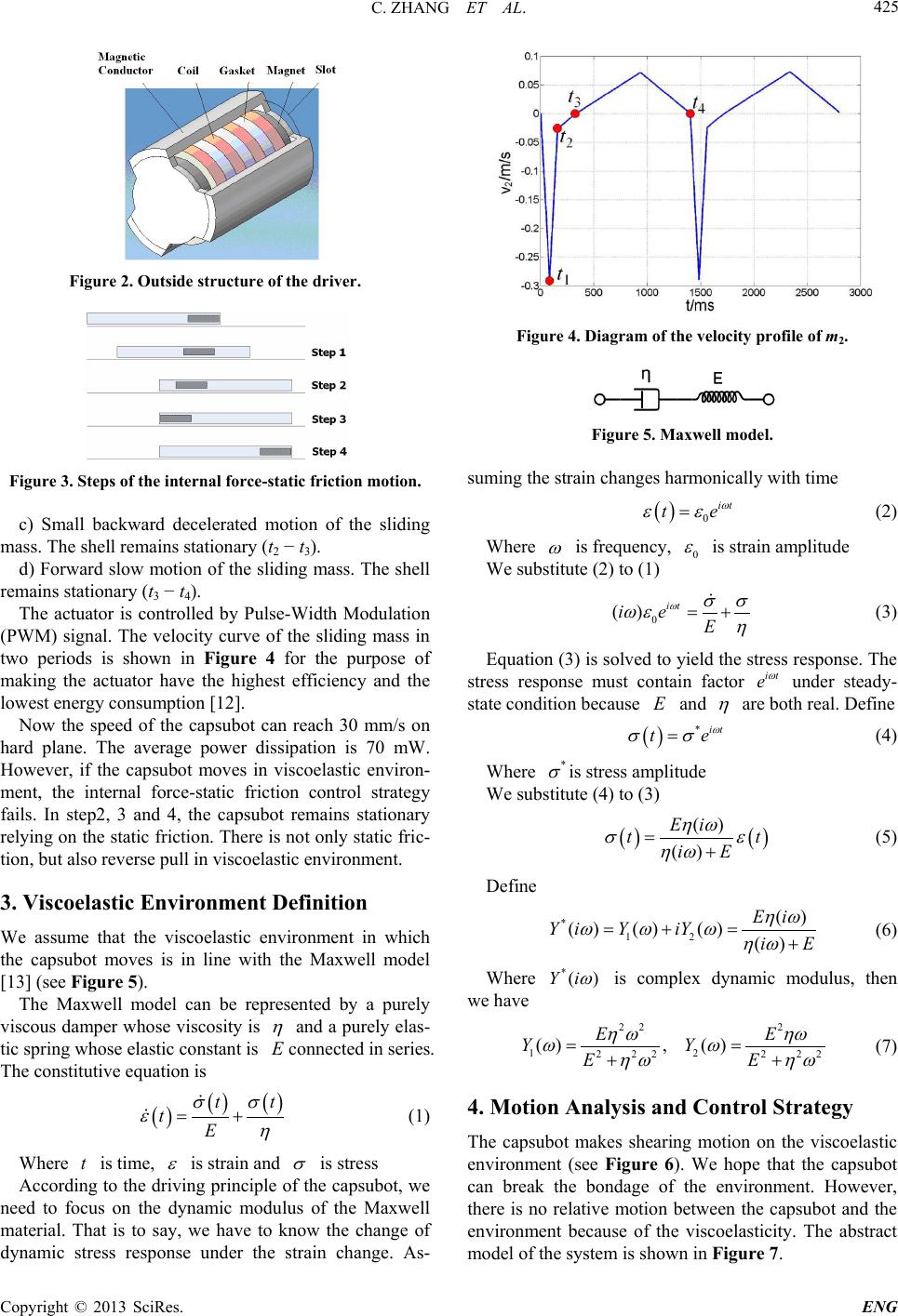 C. ZHANG ET AL. Copyright © 2013 SciRes. ENG 425 Figure 2. Outside structure of the driver. Figure 3. Steps of the internal force-static friction motion. c) Small backward decelerated motion of the sliding mass. The shell remains stationary (t2 − t3). d) Forward slow motion of the sliding mass. The shell remains stationary (t3 − t4). The actuator is controlled by Pulse-Width Modulation (PWM) signal. The velocity curve of the sliding mass in two periods is shown in Figure 4 for the purpose of making the actuator have the highest efficiency and the lowest ene rgy cons umption [12]. Now the speed of the capsubot can reach 30 mm/s on hard plane. The average power dissipation is 70 mW. However, if the capsubot moves in viscoelastic environ- ment, the internal force-static friction control strategy fails. In step2, 3 and 4, the capsubot remains stationary relying on the static friction. There is not only static fri c- tion, but also reverse pull in viscoelastic environment. 3. Viscoelastic Environment Definition We assume that the viscoelastic environment in which the capsubot moves is in line with the Maxwell model [13] (see Figure 5). The Maxwell model can be represented by a purely viscous damper whose viscosity is η and a purely elas- tic sprin g whose elastic constant is E connected in series. The constitutive equation is ( )( )( ) tt tE σσ εη = + (1) Where t is time, ε is strain and σ is stress According to the driving principle of the capsubot, we need to focus on the dynamic modulus of the Maxwell material. That is to say, we have to know the change of dynamic stress response under the strain change. As- Figure 4. Diagram of the velocity profile of m2. Figure 5. Maxwell model. suming the strain changes harmonically with time ( ) 0it te ω εε = (2) Where ω is frequency, 0 ε is strain amplitude We substitute (2) to (1) 0 () it ie E ωσσ ωε η = + (3) Equation (3) is solved to yield the stress response. The stress response must contain factor it e ω under steady- state condition because E and η are both real. Define ( ) *it te ω σσ = (4) Where * σ is stress amplitude We substitute (4) to (3) ( )( ) () () Ei tt iE ηω σε ηω =+ (5 ) Define *12 () ( )()()() Ei Y iYiYiE ηω ωω ω ηω =+= + (6) Where * ()Yi ω is complex dynamic modulus, then we have 22 2 12 2 222 22 (), () EE YY EE η ωηω ωω ηω ηω = = ++ (7) 4. Motion Analysis and Control Strategy The capsubot makes shearing motion on the viscoelastic environment (see Figure 6). We hope that the capsubot can break the bondage of the environment. However, there is no relative motion between the capsubot and the environment because of the viscoelasticity. The abstract model of the system is shown in Figure 7. 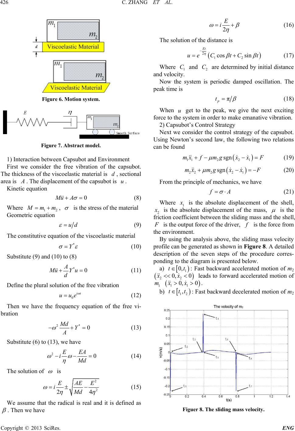 C. ZHANG ET AL. Copyright © 2013 SciRes. ENG 426 Figure 6. Motion system. Figure 7. Abstract model. 1) Interaction between Capsubot and Environment First we consider the free vibration of the capsubot. The thickness of the viscoelastic material is d , sectional area is A . The displacement of the capsubot is u . Kinetic equation 0Mu A σ += (8) Where 12 Mmm= + , σ is the stress of the material Geometric equation ud ε = (9) The constitutive equation of the viscoelastic material * Y σε = (10) Substitute (9) and (10) to (8) * 0 A MuY u d += (11) Define the plural solution of the free vibration 0it u ue ω = (12) Then we have the frequency equation of the free vi- bration 2* 0 Md Y A ω − += (1 3) Substitute (6) to (13), we have 2 0 E EA iMd ωω η − −= (1 4) The solution of ω is 2 2 24 EAE E iMd ωηη =±− (15 ) We assume that the radical is real and it is defined as β . Then we have 2 E i ωβ η = + (16) The solution of the distance is ( ) 212 cos sin Et ue CtCt ηββ − = + (17) Where 1 C and 2 C are determined by initial distance and velocity. Now the system is periodic damped oscillation. The peak time is π p t β = (18) When u get to the peak, we give the next exciting force to the system in order to make emanative vibration. 2) Capsubot’s Control Strategy Next we consider the control strategy of the capsubot. Using Newton’s second law, the following two relations can be found ( ) 1122 1 sgnmxfmgx xF µ +−− = (19) ( ) 2222 1 sgnmxmgxxF µ + −=− (20) From the principle of mechanics, we have fA σ = ⋅ (21) Where 1 x is the absolute displacement of the shell, 2 x is the absolute displacement of the mass, µ is the friction coefficient between the sliding mass and the shell, F is the out put force of the driver, f is the force from the environment. By using the analysis above, the sliding mass velocity profile can be generated as shown in Figure 8. A detailed description of the seven steps of the procedure corres- ponding to the diagram is presented below. a) [ ) 1 0,tt∈ : Fast backward accelerated motion of m2 ( ) 22 0, 0xx<< < leads to forward accelerated motion of 1 m ( ) 11 0, 0xx>> . b) [ ) 12 ,t tt∈ : Fast backward decelerated motion of m2 Figuer 8. The sliding mass velocity. 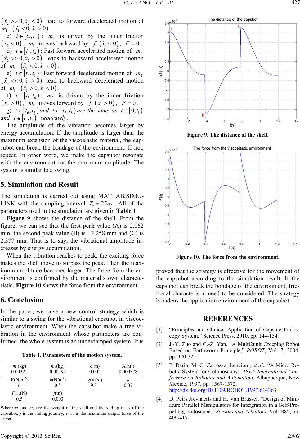 C. ZHANG ET AL. Copyright © 2013 SciRes. ENG 427 ( ) 22 0, 0xx>> < lead to forward decelerated motion of 1 m ( ) 11 0, 0xx<> . c) [ ) 23 ,t tt∈ : 2 m is driven by the inner friction ( ) 2 0x< , 1 m moves ba c kward by f ( ) 1 0x< , 0F= . d) [ ) 34 ,t tt∈ : Fast forward accelerated motion of 2 m ( ) 22 0, 0xx>>> leads to backward accelerated motion of 1 m ( ) 11 0, 0xx<< . e) [ ) 45 ,t tt∈ : Fast forward decelerated motion of 2 m ( ) 22 0, 0xx<< > lead to backward decelerated motion of 1 m ( ) 11 0, 0xx>< . f) [ ) 56 ,t tt∈ : 2 m is driven by the inner friction ( ) 2 0x> , 1 m moves forward by f ( ) 1 0x> , 0F= . g) [ ) 67 ,t tt∈ and [ ) 78 ,t tt∈ are the same as [ ) 1 0,tt∈ and [ ) 12 ,t tt∈ separately. The amplitude of the vibration becomes larger by energy accumulation. If the amplitude is larger than the maximum extension of the viscoelastic material, the cap- subot can break the bondage of the environment. If not, repeat. In other word, we make the capsubot resonate with the environment for the maximum amplitude. The system is similar to a swing. 5. Simulation and Result The simulation is carried out using MATLAB/SIMU- LINK with the sampling interval 25 s T ns= . All of the parameters used in the simulation are given in Table 1. Figure 9 shows the distance of the shell. From the figure, we can see that the first peak value (A) is 2.062 mm, the second peak value (B) is −2.258 mm and (C) is 2.377 mm. That is to say, the vibrational amplitude in- creases by energy accumulation. When the vibration reaches to peak, the exciting force makes the shell move to surpass the peak. Then the max- imum amplitude becomes larger. The force from the en- vironment is confirmed by the material’s own characte- ristic. Figure 10 shows the force from the environment. 6. Conclusion In the paper, we raise a new control strategy which is similar to a swing for the vibrational capsubot in viscoe- lastic environment. When the capsubot make a free vi- bration in the environment whose parameters are con- firmed, the whole system is an underd amped system. It is Table 1. Parameters of the motion system. m1(kg) 0.00321 m2(kg) 0.00794 d(m) 0.002 A(m2) 0.000378 E(N/m2) 6 η(N/m2) 0.5 g(m/ s2) 9.81 μ 0.07 Fmax(N) 0.5 j(m) 0.003 Where m1 and m2 are the weight of the shell and the sliding mass of the capsubot; j is the sliding journey; Fmax is the maximum output force of the driver. Figure 9. The distance of the shell. Figure 10. The force from the environment. proved that the strategy is effective for the movement of the capsubot according to the simulation result. If the capsubot can break the bondage of the environment, fric- tional characteristic need to be considered. The strategy broadens the application environment of the capsubot. REFERENCES [1] “Principles and Clinical Application of Capsule Endos- copy System,” Science Press, 2010, pp. 144-154. [2] J.-Y. Zuo and G.-Z. Yan, “A Multi2unit Creeping Robot Based on Earthworm Principle,” ROBOT, Vol. 7, 2004, pp. 320-324. [3] P. Dario, M. C. Carrozza, Lencioni, et al., “A Micro Ro- botic System for Colonoscopy,” IEEE International Con- ference on Robotics and Automation, Albupuerque, New Mexico, 1997, pp. 1567-1572. http://dx.doi.org/10.1109/ROBOT.1997.614363 [4] D. Peir s Jreynaerts and H. Van Brussel, “Design of Mini- ature Parallel Manipulators for Intergration in a Self-Pro- pelling Endoscope,” Sensors and Actuators, Vol. B85, pp. 409-417.  C. ZHANG ET AL. Copyright © 2013 SciRes. ENG 428 [5] X.-Y. Jian, T. Mei, X.-H. Wang, “Driving Method of an Endoscopic Robot Capsule by External Magnetic Field,” ROBOT, Vol. 27, No. 4, 2005, pp. 367-372. [6] Olympus Medical System Corporation, “Development of Capsule Endoscope and Peripheral Technologies for Fur- ther Expansion and Progress in Endoscope Applications.” [7] Y. S. Zhang, Z. G. Li, S. P. Jing, et al., “Characteristics of Magnetic Tensile Force along Axial Direction of a Cap- sule Micro Robot Applied in Intestine,” Chinese Mecha- nical Engineering, Vol. 18, No. 14, 2007, pp. 1709-1713. [8] M. Sendoh, K. Ishiyama and K. I. Arai, “Fabrication of Magnetics Actuator for Use in a Capsule Endoscope,” IEEE Transactions on Magnetics, Vol. 39, 2003, pp. 3232-3234. http://dx.doi.org/10.1109/TMAG.2003.816731 [9] A. Moglia, A. Menciassi, M. Schurr and P. Dario, “Wir e- less Capsu le Endosco py: From Diagnostic Decices to Mul- tipurpose Robotic System,” Biomed Microdevis, Vol. 9, 2007, pp. 235-243. http://dx.doi.org/10.1007/s10544-006-9025-3 [10] M. Quirini, R. J. Webster III, A. Menciassi and P. Dario, “Design of A Pill-Sized 12-Legged Endoscopic Capsule Robot,” IEEE International Conference on Robotics and Automation, Roma, 2007, pp. 1856-1862. [11] G. Su, C. Zhang, R. J. Tan and H. Y. Li, “A Design of the Electromagnetic Driver for the “Internal Force-Static Fri- ction,” Capsubot, IEEE/RSJ International Conference on Intelligent Robots and Systems, 2009, pp. 613-617. [12] H. Y. Li, K. Furuta and F. L. Chernousko, “Motion Gene- ration of the Capsubot Using Internal Force and Static Friction,” IEEE Conference on Decision and Control, 2006, pp. 6575-6580. http://dx.doi.org/10.1109/CDC.2006.377472 [13] “Principles of Polymer Engineering ,” 2nd Edition, Ox- ford University Press, 1997, pp. 117-176. |