

Paper Menu >>
Journal Menu >>
 J. Biomedical Science and Engineering, 2013, 6, 21-28 JBiSE http://dx.doi.org/10.4236/jbise.2013.612A004 Published Online December 2013 (http://www.scirp.org/journal/jbise/) Mechanical response of uterine tissue under the influence of hemostatic clips: A non-linear finite-element approach Mark A. Nicosia1*, Donald A. Wood1, Daniel Mazzucco2 1Department of Mechanical Engineering, Widener University, Chester, USA 2ZSX Medical, LLC., King of Prussia, usa Email: *[email protected] Received 30 September 2013; revised 28 October 2013; accepted 14 November 2013 Copyright © 2013 Mark A. Nicosia et al. This is an open access article distributed under the Creative Commons Attribution License, which permits unrestricted use, distribution, and reproduction in any medium, provided the original work is properly cited. ABSTRACT A modeling strategy to predict the ability of surgical clips to achieve mechanical hemostasis when applied to the cut edge of a thick and muscular tissue is pre- sented in this work. Although such a model may have broad utility in the design of hemostatic clips and oth- er surgical and wound closure applications, our par- ticular focus was on uterine closure following a Cesa- rean delivery. Mechanical closure of a blood vessel, which is the first step in the hemostatic process, is established when the compressive forces on the outer surface of a blood vessel are sufficient to overcome the local blood pressure and collapse the vessel. For thick tissue, forces applied to the tissue surface set up a stress distribution within the tissue that, if sufficient to mechanically close all vessels, will lead to cessation of local blood flow. The fo cus of the current work was on utilization of a planar and nonlinear finite element model to predict the pressure distribution within ute- rine tissue under the influence of hemostatic clips. After experimental model validation with a polymer tissue phantom, design curves were numerically de- veloped, which consisted of the clip force necessary to achieve hemostasis for a given thickness tissue as well as the resulting deformed tissue thickness. Such curves could form the basis for a preliminary clip design, which would provide initial design guidance before more expensive experimental studies were re- quired. Keywords: Medical Device Design; Hemostasis; Finite Element Modeling; Tissue Modeling; Myometrial Tissue 1. INTRODUCTION Computer simulations are routinely used to aid in the design and development of engineered products. Typical computational models consider stress analysis to predict material failure, fluid dynamics to predict fluid shear stress imposed on structures, or heat transfer to predict temperature distributions. Application of simulations to medical device design is complicated by many factors, such as uncertainty in tissue material properties and ge- ometry due to physiological variation [1], nonlinear con- stitutive models [2], and the presence of non-traditional or multi-physics effects (e.g., muscle contraction, blood flow within tissue, and fluid-structure interaction). The focus of the current work is to model via a nonlinear fi- nite element formulation the mechanical interaction be- tween hemostatic clips and uterine tissue in closure ap- plications during cesarean delivery, furnishing useful indications for clip design. During cesarean deliveries, which account for appro- ximately 32% of births in the United States [3], the baby is delivered through incisions in the uterus and abdomen rather than vaginally. Once the baby and placenta have been delivered, the surgeon sutures the incisions closed, starting with the uterine wall and working outward to- wards the body surface. There are both short-term and long-term risks associated with cesarean delivery, in- cluding hemorrhage, injury to urogenital and gastrointes- tinal organs, and uterine complications affecting subse- quent pregnancies. In addition, the formation of adhe- sions, common after pelvic surgery, is considered to be a leading cause of infertility [4]. A surgical closure device that reduces these risks would be of great value. Hemostatic clips are an alternative to sutures for sur- gical closure, such as the Raney clip used on the scalp. Mechanically, clips and sutures both apply compressive forces to the tissue to occlude transected vessels and stop blood flow; they differ in that clips which do not pene- trate the tissue, but rather apply a force to the surface of the tissue and rely on internal compressive stress within the tissue for vessel closure. This lack of penetration of *Corresponding author. OPEN ACCESS 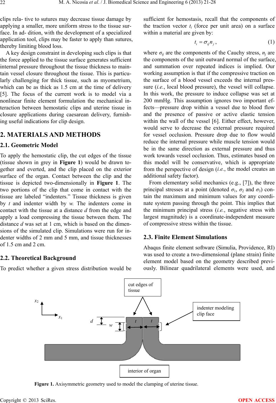 M. A. Nicosia et al. / J. Biomedical Science and Engineering 6 (2013) 21-28 22 clips rela- tive to sutures may decrease tissue damage by applying a smaller, more uniform stress to the tissue sur- face. In ad- dition, with the development of a specialized application tool, clips may be faster to apply than sutures, thereby limiting blood loss. A key design constraint in developing such clips is that the force applied to the tissue surface generates sufficient internal pressure throughout the tissue thickness to main- tain vessel closure throughout the tissue. This is particu- larly challenging for thick tissue, such as myometrium, which can be as thick as 1.5 cm at the time of delivery [5]. The focus of the current work is to model via a nonlinear finite element formulation the mechanical in- teraction between hemostatic clips and uterine tissue in closure applications during caesarean delivery, furnish- ing useful indications for clip design. 2. MATERIALS AND METHODS 2.1. Geometric Model To apply the hemostatic clip, the cut edges of the tissue (tissue shown in grey in Figure 1) would be drawn to- gether and everted, and the clip placed on the exterior surface of the organ. Contact between the clip and the tissue is depicted two-dimensionally in Figure 1. The two portions of the clip that come in contact with the tissue are labeled “indenters.” Tissue thickness is given by t and indenter width by w. The indenters come in contact with the tissue at a distance d from the edge and apply a load compressing the tissue between them. The distance d was set at 1 cm, which is based on the dimen- sions of the simulated clip. Simulations were run for in- denter widths of 2 mm and 5 mm, and tissue thicknesses of 1.5 cm and 2 cm. 2.2. Theoreti cal Background To predict whether a given stress distribution would be sufficient for hemostasis, recall that the components of the traction vector ti (force per unit area) on a surface within a material are given by: iij tj n , (1) where σij are the components of the Cauchy stress, nj are the components of the unit outward normal of the surface, and summation over repeated indices is implied. Our working assumption is that if the compressive traction on the surface of a blood vessel exceeds the internal pres- sure (i.e., local blood pressure), the vessel will collapse. In this work, the pressure to induce collapse was set at 200 mmHg. This assumption ignores two important ef- fects—pressure drop within a vessel due to blood flow and the presence of passive or active elastic tension within the wall of the vessel [6]. Either effect, however, would serve to decrease the external pressure required for vessel occlusion. Pressure drop due to flow would reduce the internal pressure while muscle tension would be in the same direction as external pressure and thus work towards vessel occlusion. Thus, estimates based on this model will be conservative, which is appropriate from the perspective of design (i.e., the model creates an additional safety factor). From elementary solid mechanics (e.g., [7]), the three principal stresses at a point (denoted σ1, σ2 and σ3) con- tain the maximum and minimum values for any coordi- nate system passing through the point. This implies that the minimum principal stress (i.e., negative stress with largest magnitude) is a coordinate-independent measure of compressive stress within the tissue. 2.3. Finite Element Simulations Abaqus finite element software (Simulia, Providence, RI) was used to create a two-dimensional (plane strain) finite element model based on the geometry described previ- ously. Bilinear quadrilateral elements were used, and t t w d indenter modeling clip face interior of organ x 1 x 2 cut edges of tissue Figure 1. Axisymmetric geometry used to model the clamping of uterine tissue. Copyright © 2013 SciRes. OPEN ACCESS 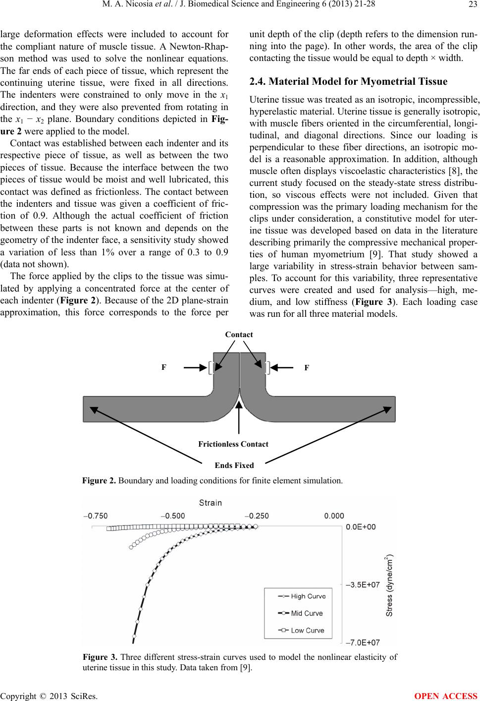 M. A. Nicosia et al. / J. Biomedical Science and Engineering 6 (2013) 21-28 23 large deformation effects were included to account for the compliant nature of muscle tissue. A Newton-Rhap- son method was used to solve the nonlinear equations. The far ends of each piece of tissue, which represent the continuing uterine tissue, were fixed in all directions. The indenters were constrained to only move in the x1 direction, and they were also prevented from rotating in the x1 − x2 plane. Boundary conditions depicted in Fig- ure 2 were applied to the model. Contact was established between each indenter and its respective piece of tissue, as well as between the two pieces of tissue. Because the interface between the two pieces of tissue would be moist and well lubricated, this contact was defined as frictionless. The contact between the indenters and tissue was given a coefficient of fric- tion of 0.9. Although the actual coefficient of friction between these parts is not known and depends on the geometry of the indenter face, a sensitivity study showed a variation of less than 1% over a range of 0.3 to 0.9 (data not shown). The force applied by the clips to the tissue was simu- lated by applying a concentrated force at the center of each indenter (Figure 2). Because of the 2D plane-strain approximation, this force corresponds to the force per unit depth of the clip (depth refers to the dimension run- ning into the page). In other words, the area of the clip contacting the tissue would be equal to depth × width. 2.4. Material Model for Myometrial Tissue Uterine tissue was treated as an isotropic, incompressible, hyperelastic material. Uterine tissue is generally isotropic, with muscle fibers oriented in the circumferential, longi- tudinal, and diagonal directions. Since our loading is perpendicular to these fiber directions, an isotropic mo- del is a reasonable approximation. In addition, although muscle often displays viscoelastic characteristics [8], the current study focused on the steady-state stress distribu- tion, so viscous effects were not included. Given that compression was the primary loading mechanism for the clips under consideration, a constitutive model for uter- ine tissue was developed based on data in the literature describing primarily the compressive mechanical proper- ties of human myometrium [9]. That study showed a large variability in stress-strain behavior between sam- ples. To account for this variability, three representative curves were created and used for analysis—high, me- dium, and low stiffness (Figure 3). Each loading case was run for all three material models. F F Contact Frictionless Contact Ends Fixed Figure 2. Boundary and loading conditions for finite element simulation. Figure 3. Three different stress-strain curves used to model the nonlinear elasticity of uterine tissue in this study. Data taken from [9]. Copyright © 2013 SciRes. OPEN ACCESS 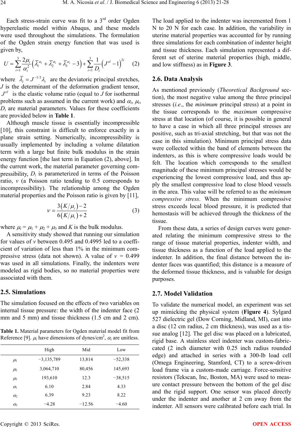 M. A. Nicosia et al. / J. Biomedical Science and Engineering 6 (2013) 21-28 24 Each stress-strain curve was fit to a 3rd order Ogden hyperelastic model within Abaqus, and these models were used throughout the simulations. The formulation of the Ogden strain energy function that was used is given by, 33 2 123 2 11 21 3 iii i el i ii i i U D 1J (2) where 1/3 ii J are the deviatoric principal stretches, J is the determinant of the deformation gradient tensor, el J is the elastic volume ratio (equal to J for isothermal problems such as assumed in the current work) and i, i, Di are material parameters. Values for these coefficients are provided below in Table 1. Although muscle tissue is essentially incompressible [10], this constraint is difficult to enforce exactly in a plane strain setting. Numerically, incompressibility is usually implemented by including a volume dilatation term with a large but finite bulk modulus in the strain energy function [the last term in Equation (2), above]. In the current work, the material parameter governing com- pressibility, Di is parameterized in terms of the Poisson ratio, ν (a Poisson ratio tending to 0.5 corresponds to incompressibility). The relationship among the Ogden material properties and the Poisson ratio is given by [11], 32 62 i i K K (3) where i = 1 + 2 + 3 and K is the bulk modulus. A sensitivity study showed that running our simulation for values of ν between 0.495 and 0.4995 led to a coeffi- cient of variation of less than 1% in the minimum com- pressive stress (data not shown). A value of ν = 0.499 was used in all simulations. Finally, the indenters were modeled as rigid bodies, so no material properties were associated with them. 2.5. Simulations The simulation focused on the effects of two variables on internal tissue pressure: the width of the indenter face (2 mm and 5 mm) and tissue thickness (1.5 cm and 2 cm). Table 1. Material parameters for Ogden material model fit from Reference [9]. i have dimensions of dynes/cm2, i are unitless. High Mid Low 1 −3,135,789 13,814 −52,338 2 3,064,710 80,456 145,693 3 193,610 12.3 −38,515 1 6.10 2.84 4.33 2 6.39 9.23 8.22 3 −4.28 −12.56 −4.60 The load applied to the indenter was incremented from 1 N to 20 N for each case. In addition, the variability in uterine material properties was accounted for by running three simulations for each combination of indenter height and tissue thickness. Each simulation represented a dif- ferent set of uterine material properties (high, middle, and low stiffness) as in Figure 3. 2.6. Data Analysis As mentioned previously (Theoretical Background sec- tion), the most negative value among the three principal stresses (i.e., the minimum principal stress) at a point in the tissue corresponds to the maximum compressive stress at that location (of course, it is possible in general to have a case in which all three principal stresses are positive, such as tri-axial stretching, but that was not the case in this simulation). Minimum principal stress data were collected within the band of elements between the indenters, as this is where compressive loads would be felt. The location which corresponds to the smallest magnitude of these minimum principal stresses would be experiencing the lowest compressive load, and thus ap- ply the smallest compressive load to close blood vessels in the area. This value will be referred to as the minimum compressive stress. When the minimum compressive stress exceeds local blood pressure, it is predicted that hemostasis will be achieved through the thickness of the tissue. From these data, a series of design curves were gener- ated relating the minimum compressive stress to the range of tissue material properties, indenter width, and tissue thickness as a function of the load applied to the indenter. In addition, the final distance between the in- denter faces was quantified; this distance is a measure of the deformed tissue thickness, and is valuable for design purposes. 2.7. Model Validation To validate the numerical model, an experiment was set up mimicking the physical system (Figure 4). Sylgard 527 dielectric gel (Dow Corning, Midland, MI), cast into a disc (12 cm radius, 2 cm thickness), was used as a tis- sue analog [12]. The gel disc was placed on a lubricated, rigid base. A stainless steel indenter was custom-fabric- cated (2 inch diameter with 0.25 inch radius rounded edge) and attached in series with a 300-lb load cell (Omega Engineering, Stamford, CT) to a screw-driven load frame via a custom-made carriage. Force-sensitive resistors (Tekscan, Inc, Boston, MA) were used to meas- ure contact pressure between the bottom of the gel disc and the rigid support. One sensor was placed directly under the indenter and another at 2 cm away from the indenter. All sensors were calibrated before each trial. In Copyright © 2013 SciRes. OPEN ACCESS  M. A. Nicosia et al. / J. Biomedical Science and Engineering 6 (2013) 21-28 25 a given trial, a given displacement was applied to the carriage while the indenter force and contact pressure were measured. Both pressure sensor and load cell data were collected using a digital data acquisition system (National Instruments, Austin, TX). Prior to the indentation tests, an unconfined compres- sion test was performed on smaller gel discs (4.5 cm di- ameter) to quantify the material properties of the gel. In these experiments, the indenter was replaced with a lu- bricated flat metal plate. The gel material was fit to a Neo-Hookean material model ( = 78,192 dynes/cm2, ν = 0.499). Note that although the material model is slightly different from the one used for the tissue, the one-pa- rameter Ogden model is equivalent to a Neo-Hookean model. An axisymmetric finite element mesh was created of the gel and indenter (Figure 5). The same element for- mulation and solution method as described for the myo- metrial tissue model was used in this model. A dis- placement boundary condition was applied to the in- denter and frictionless contact was enforced at the boundary between the gel and the rigid base. The reac- tion force of the indenter and the base contact pressure were computed and compared to experimental values for the same indenter displacement. Accurate prediction of the base contact pressure for the tissue-like material will be used as verification of the prediction of compressive stresses within simulated myometrial tissue. Pressur e Sensors Load Cell Gel Disc Ind enter Figure 4. Experimental apparatus used for validation of com- puter model. Figure 5. Axisymmetric finite element mesh of gel and in- denter used for validation. 3. RESULTS 3.1. Valid ati on Model Before considering the myometrial tissue model, the validation model was first studied. For both indenter force and surface pressure, comparison between experi- mental results and simulations of the gel disc was excel- lent (Figures 6 and 7). 3.2. Myometrial Model In general, the simulated uterine tissue showed a charac- teristic stress distribution during compression by the in- denters, as shown in Figure 8 for 1.5 cm thickness tissue, a 2 mm indenter face. As expected, the deformation was significant, given the very compliant nature of muscle tissue. The minimum principal stress (i.e., largest com- pressive stress) was centered between the indenters; stress decreased in magnitude towards the indenter edge, where the tissue is in tension as it wraps around the curved portion of the indenter. Based on the full set of simulation results, design curves were created relating indenter force to the mini- mum compressive tissue stress between the indenters. A representative set of curves is shown in Figure 9 for a tissue thickness of 2 cm, an indenter width of 5 mm, and all three myometrial material models. Table 2 summa- rizes the results of the force data. The third column shows the range of forces required per cm of clip width to achieve hemostasis accounting for both high and low stress-strain curves. The deformed tissue thickness at the hemostatic load for each condition is shown in Table 3. The range of values for each thickness and width represents the thick- ness at the load required for hemostasis for low and high Table 2. Force per unit depth of clip required to achieve hemo- stasis. The values corresponding to low and high tissue stiffness tissue are presented. Tissue Thickness (cm) Indenter Width (mm) Force Range Required for Hemostasis (N/cm) 2 2.8 - 3.5 1.5 5 3 - 4 2 3.8 - 5 2 5 4 - 5.4 Table 3. Deformed tissue thickness of each sample at hemo- static load. The values corresponding to low and high tissue stiffness tissue are presented. Tissue Thickness (cm) Indenter Width (mm) Tissue thickness at hemostatic load (cm) 2 0.50 - 1.17 1.5 5 0.54 - 1.19 2 0.63 - 1.54 2 5 0.69 - 1.57 Copyright © 2013 SciRes. OPEN ACCESS  M. A. Nicosia et al. / J. Biomedical Science and Engineering 6 (2013) 21-28 Copyright © 2013 SciRes. 26 0.0E+00 2.5E+06 5.0E+06 7.5E+06 00.25 0.5 0.751 IndentorForce (Dy ne) Indente r Displa ceme nt (cm) FEA Data Test Data Figure 6. Comparison of indenter force vs. displacement curve for simulation and experiment, showing excellent agreement. 0.E+00 5.E+05 1.E+06 2.E+06 2.E+06 00.25 0.50.751 Pressure (dynes/sq cm) Indenter Displacement (cm) C entr al Sens or ( FEA) C entr al Sens or ( Exp) Out er Sens or ( FEA) Out er Sens or ( Exp) Figure 7. Comparison of contact pressure for simulation and experiment, showing excellent agree- ment. The central sensor was located directly under the indenter and the outer sensor was 2 cm out from center of the indenter. stiffness curves at each tissue width and indenter width. Note that the large range in strains, due to the non-linear stiffness of the tissue. For example, for the 1.5 cm tissue and 2 mm indenter face, tissue compressed to 33% of its original thickness for the high compliance tissue while only deforming to 80% of the original thickness for the low-compliance curve. OPEN ACCESS 4. DISCUSSION The goal of this work was to develop, validate, and apply a framework to utilize finite element modeling in the design of hemostatic clips for surgical closure applica- tions. Surgical closure techniques aim to mechanically facilitate apposition of cut edges of tissue to promote wound healing, while stopping blood flow to allow he- mostasis to occur. The central issue addressed in this work was the ability of a hemostatic clip applied at the surface of a thick and muscular organ to provide suffi- cient internal pressure to achieve mechanical hemostasis throughout the tissue. Although the particular focus was on uterine tissue at full-term pregnancy, the work is broadly applicable to surgical closure of other thick- walled organs. The guiding principle underlying the analysis is that if the compressive stress acting on a blood vessel within a tissue exceeds local blood pressure, the vessel will col- lapse and blood flow will be halted in that particular vessel. If the compressive stress throughout the entire thickness of the tissue exceeds local blood pressure, then bleeding should be stopped, allowing the clotting process to begin. To predict the distribution of compressive stress within the tissue, we utilized the finite element method. The finite element method breaks the domain into small ele- ments, over which the equations of mechanics are solved, ielding the stress distribution over the entire domain. y  M. A. Nicosia et al. / J. Biomedical Science and Engineering 6 (2013) 21-28 27 Figure 8. Distribution of minimum principal stress (dynes/cm2) for representative load case (1.5 cm tissue thickness; 2 mm indenter, mid-level material model). 0 40 80 120 160 200 0510 15 Minimum Comp. Stress between Indenter s (kPa) Force (N) Applie d to Indento r sper cm of Clip Length High Curve Mid Curve Low Curve Design Poin t Figure 9. Magnitude of minimum compressive stress between indenters (2 mm tissue thickness; 5 mm indenter width). From basic continuum mechanics, the state of stress can be represented in a coordinate-invariant manner through the three principal stresses, which are the eigenvalues of the stress tensor. Furthermore, the minimum value of the principal stress components represents the maximum compressive stress at a point in the tissue. The condition for hemostasis was that the maximum compressive stress must exceed the local blood pressure through the entire tissue thickness (i.e., the minimum value of the maximum compressive stress exceeding local blood pressure throughout the tissue). Based on the considerations above, design curves were developed which related tis- sue thickness, tissue material properties, and applied load to achieve hemostasis. The design curves were intended to aid in clip design by estimating whether a given clip design would achieve hemostasis in advance of any physical testing. To illus- trate one possible scenario, it should consider a candidate clip design that utilized elastic deformation to provide clamping force, such as in a spring-loaded clamp. In such a case, the clip would first be opened, allowing it to be placed on the tissue. The tissue would in turn deform under the pressure applied by the clip, and the system would come to a state of equilibrium. The magnitude of Copyright © 2013 SciRes. OPEN ACCESS  M. A. Nicosia et al. / J. Biomedical Science and Engineering 6 (2013) 21-28 28 the clamping force applied by the clip in this equilibrium state would depend upon the final deformed thickness of the tissue. Knowledge of the force-deflection characteri- stics of the tissue (i.e., the final deformed tissue thick- ness in response to a given clip force) would provide valuable information in designing the clip. This clamping force would then be compared to the force required for hemostasis to see if the design is viable. One of the challenges in utilizing computational mod- eling as a design tool for medical devices is the inherent uncertainty in physiological systems, both with respect to tissue constitutive models as well as geometry. In general, mechanical property data for human subjects are often scarce and may show considerable variations among in- dividuals (see Figure 3). In addition, geometric parame- ters such as tissue thickness may vary between individu- als, or even within an individual for different parts of the organ or for different times. This is particularly relevant in the current application, cesarean delivery, due to the rapid post-delivery changes in uterine thickness and ge- ometry. Our approach was to estimate upper and lower bounds for both thickness and material properties. Simu- lations were carried out between these bounds, and ranges for hemostatic force were provided, rather than a single value. Several simplifications were utilized in this work that could potentially impact the results. The geometric model utilized was strictly two-dimensional, which ne- cessitated neglecting three-dimensional effects. One such three-dimensional effect relates to the use of multiple clips to close an incision. Even if interlocking clips were used, the pressure between clips may fall below the hemostatic limit even if the pressure directly under the clip is sufficient. This issue can be handled with tightly- spaced clips and a reasonable factor of safety. Another three-dimensional effect relates to the clip-face geometry. In this work, the faces of each clip were modeled as smooth, whereas they will most likely be textured or serrated to grip the tissue without slipping. The complex stress distribution associated with such a face will be a local effect and will not affect the overall stress distribu- tion away from the clip, according to St. Venant’s Princi- ple [7]. Finally, uterine tissue was modeled to be isotro- pic, while muscle tissue is known to be anisotropic. However, in this case, the load is applied perpendicular to the fiber direction (normal to the surface), so it is rea- sonable to ignore anisotropy. This work focused specifically on closure of a full- term pregnant uterus; the development of hemostatic clips as an alternative to sutures for closure as a part of cesarean delivery has the potential to improve patient outcomes. However, the general methodology is applica- ble to a number of thick-walled organs, and has demon- strated that computational modeling can provide valuable information to aid in implant design, potentially improv- ing the efficiency of the design process. 5. ACKNOWLEDGEMENTS This study was funded by ZSX Medical and Ben Franklin Technology Partners of Southeastern PA. REFERENCES [1] Taylor, C.A. and Figueroa, C.A. (2009) Patient-specific modeling of cardiovascular mechanics. Annual Review of Biomedical Engineering, 11, 109-134. http://dx.doi.org/10.1146/annurev.bioeng.10.061807.1605 21 [2] Maceri, F., Marino, M. and Vairo, G. (2010) A unified multiscale mechanical model for soft collagenous tissues with regular fiber arrangement. Journal of Biomechanics, 43, 355-363. http://dx.doi.org/10.1016/j.jbiomech.2009.07.040 [3] VitalStats, 2010. http://www.cdc.gov/nchs/vitalstats.htm [4] Alpay, Z., Saed, G. and Diamond, M.P. (2008) Postop- erative adhesions: From formation to prevention. Semi- nars in Reproductive Medicine, 26, 313-321. http://dx.doi.org/10.1055/s-0028-1082389 [5] Cunningham, F., Leveno, K., Bloom, S., Hauth, J., Gil- strap, L. and Wenstrom, K. (2005) Williams obstetrics. 22nd Edition, McGraw Hill, New York. [6] Heil, M. (1996) The stability of cylindrical shells convey- ing viscous flow. Journal of Fluids and Structures, 10, 173-196. http://dx.doi.org/10.1006/jfls.1996.0012 [7] Lai, W.M., Rubin, D. and Krempl, E. (1993) An introduc- tion to continuum mechanics. Pergamon Press, Oxford. [8] Fung, Y.C. (1993) Biomechanics: Mechanical properties of living tissue. Springer-Verlag, New York. [9] Pearsall, G.W. (1978) Passive mechanical properties of uterine muscle (myometrium). Journal of Biomechanics, 11, 1555-1566. http://dx.doi.org/10.1016/0021-9290(78)90009-X [10] Humphrey, J.D. (2002) Cardiovascular solid mechanics: Cells, tissues, and organs. Springer-Verlag, New York. http://dx.doi.org/10.1007/978-0-387-21576-1 [11] “Abaqus 6.11 Theory Manual. Dassault Systemes,” 2011. [12] Kraitchman, D.L., Young, A.A., Chang, C.-N. and Axel, L. (1995) Semi-automatic tracking of myocardial motion in MR tagged images. IEEE Transactions on Medical Im- aging, 14, 422-433. http://dx.doi.org/10.1109/42.414606 Copyright © 2013 SciRes. OPEN ACCESS |