

Paper Menu >>
Journal Menu >>
 Journal of Applied Mathematics and Physics, 2013, 1, 65-73 Published Online November 2013 (http://www.scirp.org/journal/jamp) http://dx.doi.org/10.4236/jamp.2013.16014 Open Access JAMP Numerical Study of Turbulent Periodic Flow and He at Transfer in a Square Channel with Different Ribs Ahmed M. Bagabir, Jabril A. Khamaj, Ahmed S. Hassan Faculty of Engi neering, Ja zan University, Jazan, Saudi Arabia Email: [email protected] Received July 2013 ABSTRACT A numerical investigation has been carried out to examine turbulent flow and heat transfer characteristics in a three-dimensional ribbed square channels. Fluent 6.3 CFD code has been used. The governing equations are discretized by the second order upwind differencing scheme, decoupling with the SIMPLE (semi-implicit method for pressure linked equations) algorithm and are solved using a finite volume approach. The fluid flow and he at tran sfer char acter is- tics are presented for the Reynolds numbers based on the channel hydraulic diameter ranging from 104 to 4 × 10⁴. The effects of rib shape and orientation on heat transfer and pressure drop in the channel are investigated for six different rib configurations. Rib arrays of 45˚ inclined and 45˚ V-shaped are mounted in inline and staggered arrangements on the lower and upper walls of the channel. In addition, the performance of these ribs is also compared with the 90˚ transverse ribs. Keywords: Ribs; Square Channel; Heat Transfer; Numerical Simulation; Turbulent Flow; Periodic Flow 1. Introduction Heat transfer enhancement is an active and important field of engineering research since it increases the effec- tiveness of heat exchangers. Suitable heat transfer aug- mentation techniques may achieve considerable technical advantages and savings of costs. There are various kinds of available techniques adopted in many applications as gas turbine, heat exchanger, nuclear reactors, process industry and solar heater. The use of ribs mounted in the cooling or heating channels has been found to be an effi- cient technique of enhancing heat transfer by several investigators. The periodically positioned ribs in a chan- nel interrupt hydrodynamic and thermal boundary layers. Ribs break the laminar sub-layer and create local wall turbulence due to flow separation and reattachment, which reduce thermal resistance and greatly augment the heat transfer. It is found that if ribs are placed at an in- clination angle with respect to the axial direction, sec- ondary flows are induced over the channel, resulting in the rise in the heat transfer rate towards the upstream region with respect to the downstream one [1,2]. Al- though heat transfer is increased through the use of ribs, the pressure drop of the channel flow is also increased due to the decreased flow area effects. Therefore, the shape, spacing, height and orientation of ribs are among the most important parameters used in the design of the channel of heat exchangers. Thus, it is difficult to realize the adva nt a ge of the ri b geomet ry and arrangements. Flow and heat transfer characteristics inside a ribbed channel depend on flow conditions and geometric confi- gurations of the system. Many experimental and numeri- cal investigations were carried out to determine configu- rations that produce optimum results in terms of both heat transfer and pressure loss. Previous studies show that there are many parameters involved in such studies. • channel shape (e.g. [1]); • channel aspect ratio, H/W (e.g. [1]); • rib shape (e.g. [3-6]); • rib angle of attack, α (e.g. [2-5]); • rib width to rip height ratio, e/h (e.g. [7]); • rib pitch to rib ratio, P/e (e.g. [7]); • rib height to channel height ratio (blockage ratio), h/H (e.g. [1]); • number of ribbed walls (e.g. [3]); and • The manner by which ribs are positioned with respect to each other (inline/staggered) (e.g. [4]). It is found that the increase in rib width has an adverse effect on the heat transfer performance. The square rib produced the best heat transfer performance [7]. From the hydrodynamic point of view, since the pressure drop is raised as the rib height increases, the optimum block- age ratio, h/H, is known to be ar ound 0.1 [8,9]. Th e pitch 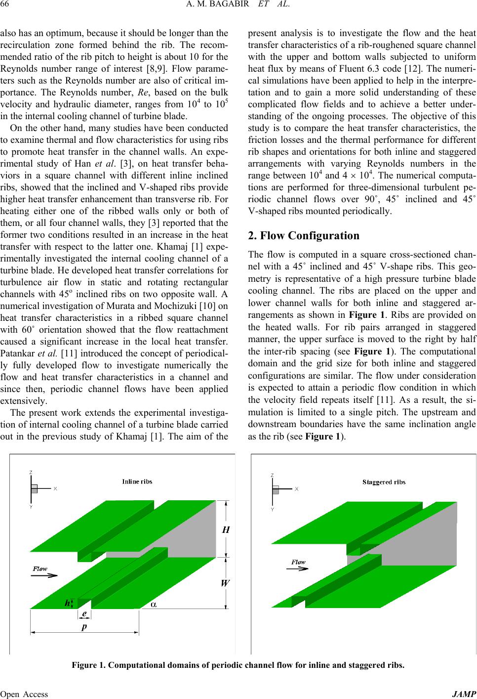 A. M. BAGABIR ET AL. Open Access JAMP 66 also has an o ptimum, because it should be longer than the recirculation zone formed behind the rib. The recom- mended ratio of the rib pitch to height is about 10 for the Reynolds number range of interest [8,9]. Flow parame- ters such as the Reynolds number are also of critical im- portance. The Reynolds number, Re, based on the bulk velocity and hydraulic diameter, ranges from 104 to 105 in the internal cooling channel of turbine blade. On the other hand, many studies have been conducted to examine thermal and flow characteristics for using r ibs to promote heat transfer in the channel walls. An expe- rimental study of Han et al. [3], on heat transfer beha- viors in a square channel with different inline inclined ribs, showed that the inclined and V-shaped ribs provide higher heat transfer enhancement than transverse rib. For heating either one of the ribbed walls only or both of them, or all four channel walls, they [3] reported that the former two conditions resulted in an increase in the heat transfer with respect to the latter one. Khamaj [1] expe- rimentally investigated the internal cooling channel of a turbine blade. He developed heat transfer correlations for turbulence air flow in static and rotating rectangular channels with 45o inclined ribs on two opposite wall. A numerical investigation of Murata and Mochizuki [10] on heat transfer characteristics in a ribbed square channel with 60˚ orientation showed that the flow reattachment caused a significant increase in the local heat transfer. Patankar et al. [11] introduced the concept of periodical- ly fully developed flow to investigate numerically the flow and heat transfer characteristics in a channel and since then, periodic channel flows have been applied extensively. The present work extends the experimental investiga- tion of internal cooling channel of a turbine blade carried out in the previous study of Khamaj [1]. The aim of the present analysis is to investigate the flow and the heat transfer characteristics of a rib-roughened square channel with the upper and bottom walls subjected to uniform heat flux by means of Fluent 6.3 code [12]. The numeri- cal simulations have been applied to help in the interpre- tation and to gain a more solid understanding of these complicated flow fields and to achieve a better under- standing of the ongoing processes. The objective of this study is to compare the heat transfer characteristics, the friction losses and the thermal performance for different rib shapes and orientations for both inline and staggered arrangements with varying Reynolds numbers in the range between 104 and 4 × 10⁴. The numerical computa- tions are performed for three-dimensional turbulent pe- riodic channel flows over 90˚, 45˚ inclined and 45˚ V-shaped ribs m ount e d pe r iodica lly. 2. Flow Configuration The flow is computed in a square cross-sectioned chan- nel with a 45˚ inclined and 45˚ V-shape ribs. This geo- metry is representative of a high pressure turbine blade cooling channel. The ribs are placed on the upper and lower channel walls for both inline and staggered ar- rangements as shown in Figure 1. Ribs are provided on the heated walls. For rib pairs arranged in staggered manner, the upper surface is moved to the right by half the inter-rib spacing (see Figure 1). The computational domain and the grid size for both inline and staggered configurations are similar. The flow under consideration is expected to attain a periodic flow condition in which the velocity field repeats itself [11]. As a result, the si- mulation is limited to a single pitch. The upstream and downstream boundaries have the same inclination angle as the rib (see Figure 1). Figure 1. Computational domains of periodic channel flow for inline and staggered ribs. 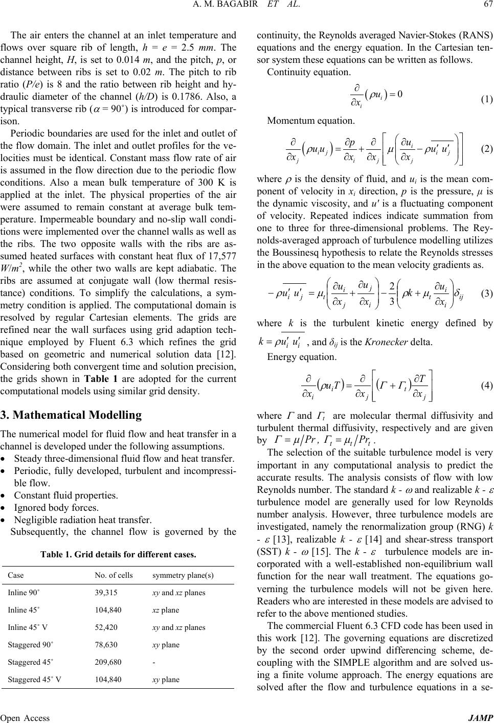 A. M. BAGABIR ET AL. Open Access JAMP 67 The air enters the channel at an inlet temperature and flows over square rib of length, h = e = 2.5 mm. The channel height, H, is set to 0.014 m, and the pitch, p, or distance between ribs is set to 0.02 m. The pitch to rib ratio (P/e) is 8 and the ratio between rib height and hy- draulic diameter of the channel (h/D) is 0.1786. Also, a typical transverse r ib ( α = 90˚) is introduced for compar- ison. Periodic boundar ies are used for the inlet and outlet of the flow domain. Th e inlet and outlet profiles for the ve- locities must be identical. Constant mass flow rate of air is assumed in the flow direction due to the periodic flow conditions. Also a mean bulk temperature of 300 K is applied at the inlet. The physical properties of the air were assumed to remain constant at average bulk tem- perature. Impermeable boundary and no-slip wall condi- tions were implemented over the chann el walls as well as the ribs. The two opposite walls with the ribs are as- sumed heated surfaces with constant heat flux of 17,577 W/m2, while the other two walls are kept adiabatic. The ribs are assumed at conjugate wall (low thermal resis- tance) conditions. To simplify the calculations, a sym- metry condition is applied. The computational domain is resolved by regular Cartesian elements. The grids are refined near the wall surfaces using grid adaption tech- nique employed by Fluent 6.3 which refines the grid based on geometric and numerical solution data [12]. Considering both convergent time and solution precision, the grids shown in Table 1 are adopted for the current computational models using similar grid density. 3. Mathematical Modelling The numerical model for fluid flow and heat transfer in a channel i s developed under the following as sumpti ons . • Steady three-dime ns ional fluid flow a nd heat transfer. • Periodic, fully developed, turbulent and incompressi- ble flow. • Consta nt fluid pro pe rties. • Ignore d bo dy forces. • Negligible radiation heat transfer. Subsequently, the channel flow is governed by the Table 1. Grid details for different cases. Case No. of cells symmetry plane(s) Inline 90˚ 39,315 xy and xz planes Inline 45˚ 104,840 xz plane Inline 45˚ V 52,420 xy and xz planes Staggered 90˚ 78,630 xy plane Staggered 45˚ 209,680 - Staggered 45˚ V 104,840 xy plane continuity, the Reynolds aver aged Navier-Stokes (RANS) equations and the energy equation. In the Cartesian ten- sor system these equations can be written as follows. Continuity equation. ( ) 0 i i u x ρ ∂= ∂ (1) Momentum equation. ( ) i iji j jij j u p uuu u xxx x ρ µρ ∂ ∂ ∂∂′′ =+− ∂∂∂ ∂ (2) where ρ is the density of fluid, and ui is the mean com- ponent of velocity in xi direction, p is the pressure, μ is the dynamic viscosity, and u' is a fluctuating component of velocity. Repeated indices indicate summation from one to three for three-dimensional problems. The Rey- nolds-averaged approach of turbulence modelling utilizes the Boussinesq hypothesis to relate the Reynolds stresses in the above equation to the mean velocity gradients as. ij i i t i j j i tji x u k x u x u uu δµρµρ ∂ ∂ +− ∂ ∂ + ∂ ∂ = ′′ −3 2 (3) where k is the turbulent kinetic energy defined by ii uuk′′ = ρ , and δij is th e Kronecker delta. Energy equation. ( )() ∂ ∂ + ∂ ∂ = ∂ ∂ j t j i ix T x Tu x ΓΓρ (4) where Γ and Γ t are molecular thermal diffusivity and turbulent thermal diffusivity, respectively and are given by ttt Pr ,Pr µΓµΓ == . The selection of the suitable turbulence model is very important in any computational analysis to predict the accurate results. The analysis consists of flow with low Reynolds number. The standard k - ω and realizable k - ε turbulence model are generally used for low Reynolds number analysis. However, three turbulence models are investigated, namely the renormalization group (RNG) k - ε [13], realizable k - ε [14] and shear-stress transport (SST) k - ω [15]. The k - ε turbulence models are in- corporated with a well-established non-equilibrium wall function for the near wall treatment. The equations go- verning the turbulence models will not be given here. Readers who are interested in these models are advised to refer to the above mentioned studies. The commercial Fluent 6.3 CFD code has been used in this work [12]. The governing equations are discretized by the second order upwind differencing scheme, de- coupling with the SIMPLE algorithm and are solved us- ing a finite volume approach. The energy equations are solved after the flow and turbulence equations in a se- 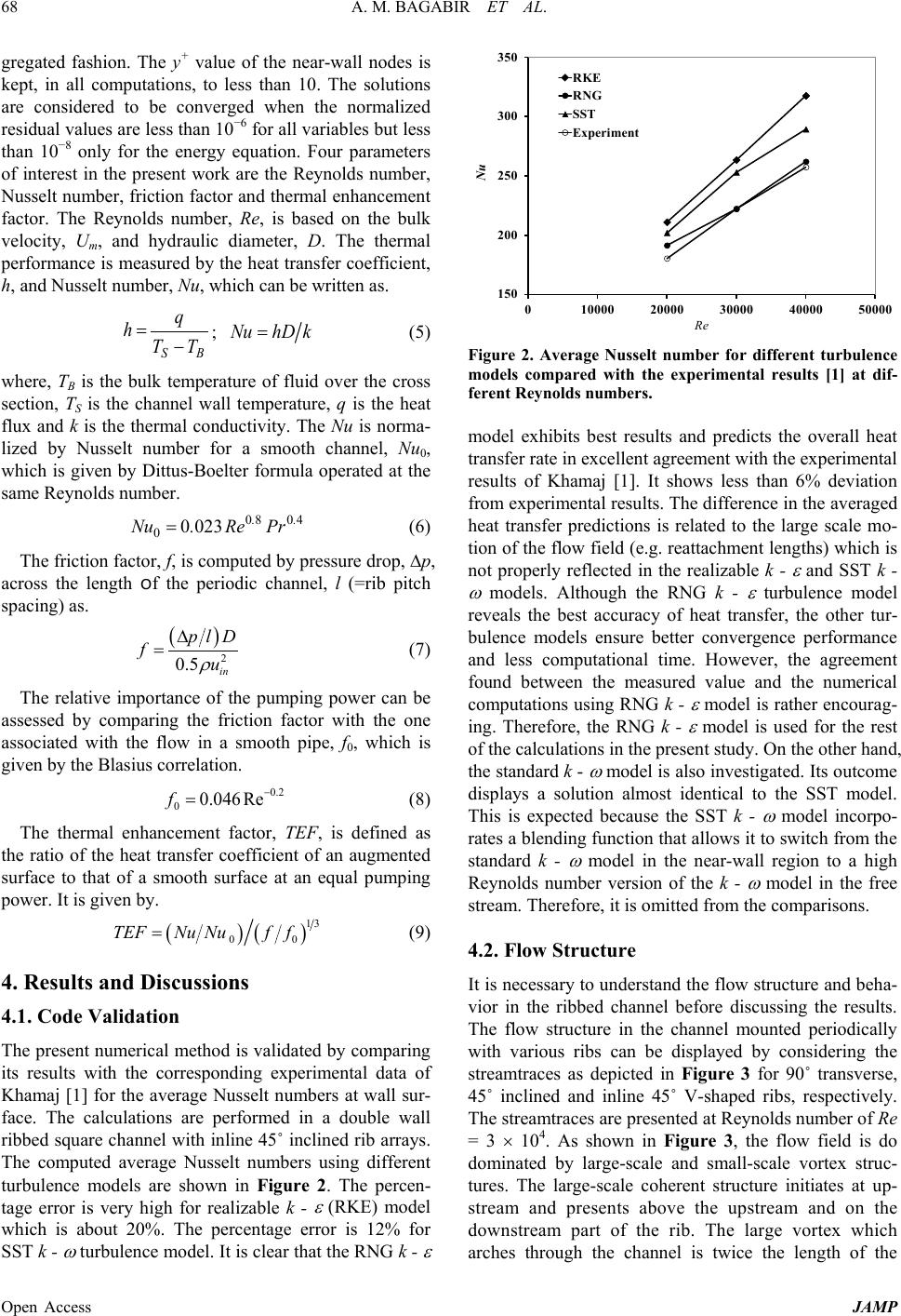 A. M. BAGABIR ET AL. Open Access JAMP 68 gregated fashion. The y+ value of the near-wall nodes is kept, in all computations, to less than 10. The solutions are considered to be converged when the normalized residual values are less than 10−6 for all variables but less than 10−8 only for the energy equation. Four parameters of interest in the present work are the Reynolds number, Nusselt number, friction factor and thermal enhancement factor. The Reynolds number, Re, is based on the bulk velocity, Um, and hydraulic diameter, D. The thermal performance is measured by the heat transfer coefficient, h, and Nusselt number, Nu, which can be written as. BS TT q h− = ; khDNu = (5) where, TB is the bulk temperature of fluid over the cross section, TS is the channel wall temperature, q is the heat flux and k is the thermal conductivity. The Nu is norma- lized by Nusselt number for a smooth channel, Nu0, which is given by Dittus-Boelter formula operated at the same Reynolds number. 4080 0 0230 .. PrRe.Nu = (6) The friction factor, f, is computed by pressure drop, ∆p, across the length of the periodic channel, l (=rib pitch spacing) as. ( ) 2 0.5 in pl D fu ρ ∆ = (7) The relative importance of the pumping power can be assessed by comparing the friction factor with the one associated with the flow in a smooth pipe, f0, which is given by the Blasius correlation. 0.2 00.046Ref− = (8) The thermal enhancement factor, TEF, is defined as the ratio of the heat transfer coefficient of an augmented surface to that of a smooth surface at an equal pumping power. It is given by. () ( ) 13 00 TEFNu Nuff= (9) 4. Results and Discussions 4.1. Code Validation The present numerical method is validated by comparing its results with the corresponding experimental data of Khamaj [1] for the average Nusselt numbers at wall sur- face. The calculations are performed in a double wall ribbed square channel with inline 45˚ inclined rib arrays. The computed average Nusselt numbers using different turbulence models are shown in Figure 2. The percen- tage error is very high for realizable k - ε (RKE) model which is about 20%. The percentage error is 12% for SST k - ω turbulence model. It is clear that the RNG k - ε Figure 2. Average Nusselt number for different turbulence models compared with the experimental results [1] at dif- ferent Reynolds numbers. model exhibits best results and predicts the overall heat transfer rate in excellent agreement with the experimental results of Khamaj [1]. It shows less than 6% deviation from experimental results. The difference in the averaged heat transfer predictions is related to the large scale mo- tion of the flow field (e.g. reattachment lengths) which is not properly reflected in the realizable k - ε and SST k - ω models. Although the RNG k - ε turbulence model reveals the best accuracy of heat transfer, the other tur- bulence models ensure better convergence performance and less computational time. However, the agreement found between the measured value and the numerical computations using RNG k - ε model is rather encourag- ing. Therefore, the RNG k - ε model is used for the rest of the calculations in the present study. On the other hand, the standard k - ω model is also investigated. Its outcome displays a solution almost identical to the SST model. This is expected because the SST k - ω model incorpo- rates a blending function that allows it to switch from the standard k - ω model in the near-wall region to a high Reynolds number version of the k - ω model in the free stream. Therefore, it is omitted from the comparisons. 4.2. Flow Structure It is necessary to understand the flow structure and beha- vior in the ribbed channel before discussing the results. The flow structure in the channel mounted periodically with various ribs can be displayed by considering the streamtraces as depicted in Figure 3 for 90˚ transverse, 45˚ inclined and inline 45˚ V-shaped ribs, respectively. The streamtraces are presented at Reynolds number of Re = 3 × 10⁴. As shown in Figure 3, the flow field is do dominated by large-scale and small-scale vortex struc- tures. The large-scale coherent structure initiates at up- stream and presents above the upstream and on the downstream part of the rib. The large vortex which arches through the channel is twice the length of the 150 200 250 300 350 010000 20000 30000 40000 50000 Nu Re RKE RNG SST Experiment 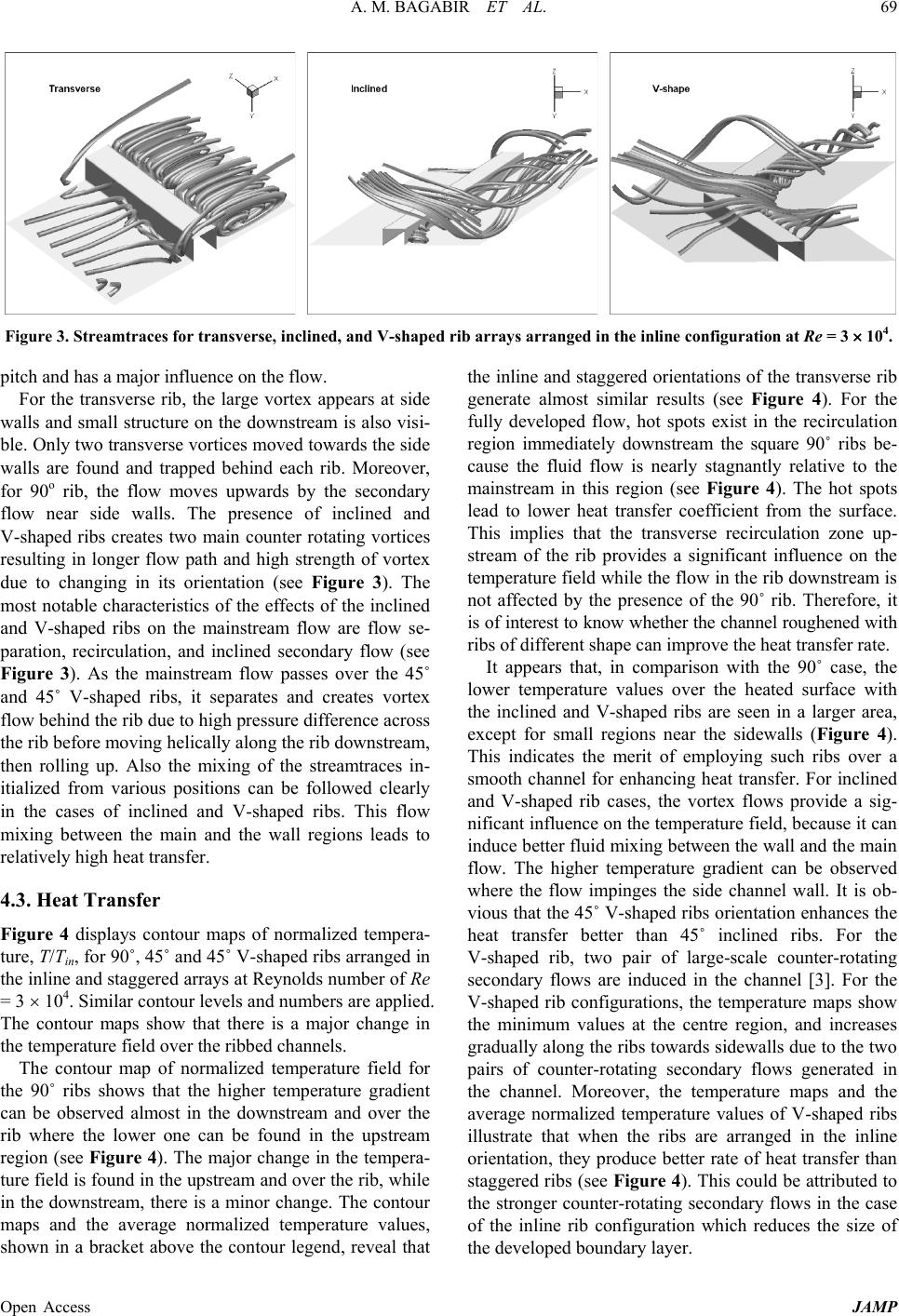 A. M. BAGABIR ET AL. Open Access JAMP 69 Figure 3. Streamtraces for transverse, inclined, and V-shaped rib arrays arranged in the inline configurati on at Re = 3 × 10⁴. pitch and has a major influence on the flow. For the transverse rib, the large vortex appears at side walls and small structure on the downstream is also visi- ble. Only two transverse vortices moved towards the side walls are found and trapped behind each rib. Moreover, for 90o rib, the flow moves upwards by the secondary flow near side walls. The presence of inclined and V-shaped ribs creates two main counter rotating vortices resulting in longer flow path and high strength of vortex due to changing in its orientation (see Figure 3). The most notable characteristics of the effects of the inclined and V-shaped ribs on the mainstream flow are flow se- paration, recirculation, and inclined secondary flow (see Figure 3). As the mainstream flow passes over the 45˚ and 45˚ V-shaped ribs, it separates and creates vortex flow behind the rib due to high pressure difference across the rib before moving helically along the rib downstream, then rolling up. Also the mixing of the streamtraces in- itialized from various positions can be followed clearly in the cases of inclined and V-shaped ribs. This flow mixing between the main and the wall regions leads to relatively high heat transfer. 4.3. Heat Transfer Figure 4 displays contour maps of normalized tempera- ture, T/Tin, for 90˚, 45˚ and 45˚ V-s haped ribs arr anged in the inline and staggered arrays at Reynolds number of Re = 3 × 10⁴. Similar contour levels and numbers are applied. The contour maps show that there is a major change in the temperature field over the ribbed channels. The contour map of normalized temperature field for the 90˚ ribs shows that the higher temperature gradient can be observed almost in the downstream and over the rib where the lower one can be found in the upstream region (see Figure 4). The major change in the tempera- ture field is found in the upstream and over the rib, while in the downstream, there is a minor change. The contour maps and the average normalized temperature values, shown in a bracket above the contour legend, reveal that the inline and staggered orientations of the transverse rib generate almost similar results (see Figure 4). For the fully developed flow, hot spots exist in the recirculation region immediately downstream the square 90˚ ribs be- cause the fluid flow is nearly stagnantly relative to the mainstream in this region (see Figure 4). The hot spots lead to lower heat transfer coefficient from the surface. This implies that the transverse recirculation zone up- stream of the rib provides a significant influence on the temperature field while th e flow in the rib downstr eam is not affected by the presence of the 90˚ rib. Therefore, it is of interest to know whether the channel roughened with ribs of different shape can improve the heat transfer rate. It appears that, in comparison with the 90˚ case, the lower temperature values over the heated surface with the inclined and V-shaped ribs are seen in a larger area, except for small regions near the sidewalls (Figure 4). This indicates the merit of employing such ribs over a smooth channel for enhancing heat transfer. For inclined and V-shaped rib cases, the vortex flows provide a sig- nificant influence on the temperature field, because it can induce better fluid mixing between the wall and the main flow. The higher temperature gradient can be observed where the flow impinges the side channel wall. It is ob- vious that the 45˚ V-shaped ribs orientation enhances the heat transfer better than 45˚ inclined ribs. For the V-shaped rib, two pair of large-scale counter-rotating secondary flows are induced in the channel [3]. For the V-shaped rib configurations, the temperature maps show the minimum values at the centre region, and increases gradually along the ribs towards sidewalls due to the two pairs of counter-rotating secondary flows generated in the channel. Moreover, the temperature maps and the average normalized temperature values of V-shaped ribs illustrate that when the ribs are arranged in the inline orientation, they produce better rate of heat transfer than staggered ribs (see Figure 4 ). This could be attributed to the stronger counter-rotating secondary flows in the case of the inline rib configuration which reduces the size of the devel o ped boundary layer. 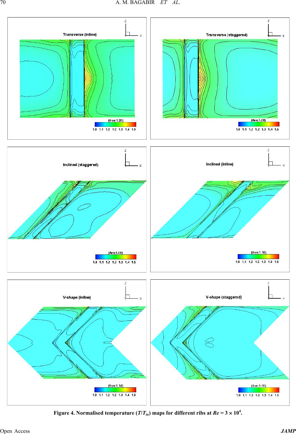 A. M. BAGABIR ET AL. Open Access JAMP 70 Figure 4. Normalised temperature (T/Tin) maps for different ribs at Re = 3 × 10⁴. 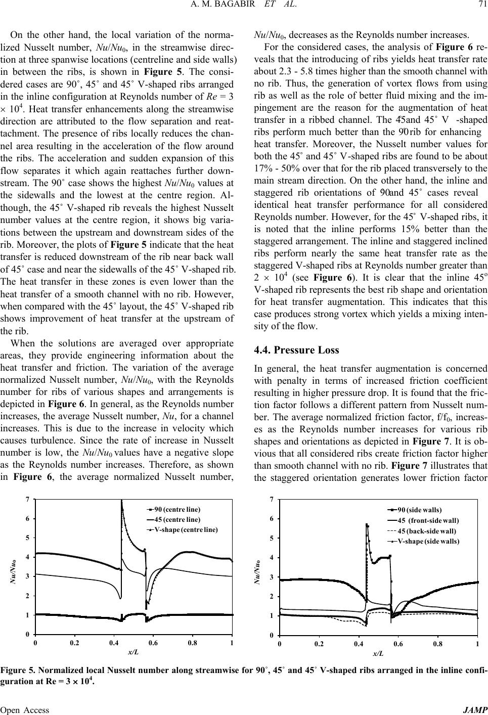 A. M. BAGABIR ET AL. Open Access JAMP 71 On the other hand, the local variation of the norma- lized Nusselt number, Nu/Nu0, in the streamwise direc- tion at three spanwise locations (centreline and side walls) in between the ribs, is shown in Figure 5. The consi- dered cases are 90˚, 45˚ and 45˚ V-shaped ribs arranged in the inline configuration at Reynolds number of Re = 3 × 10⁴. Heat transfer enhancements along the streamwise direction are attributed to the flow separation and reat- tachment. The presence of ribs locally reduces the chan- nel area resulting in the acceleration of the flow around the ribs. The acceleration and sudden expansion of this flow separates it which again reattaches further down- stream. The 90˚ case shows the highest Nu/Nu0 values at the sidewalls and the lowest at the centre region. Al- though, the 45˚ V-shaped rib reveals the highest Nusselt number values at the centre region, it shows big varia- tions between the upstream and downstream sides of the rib. Moreover, the plots of Figure 5 indicate that the heat transfer is reduced downstream of the rib near back wall of 45˚ case and near the sidewalls of the 45˚ V-shaped rib. The heat transfer in these zones is even lower than the heat transfer of a smooth channel with no rib. However, when compared with the 45˚ layout, the 45˚ V-shaped rib shows improvement of heat transfer at the upstream of the rib. When the solutions are averaged over appropriate areas, they provide engineering information about the heat transfer and friction. The variation of the average normalized Nusselt number, Nu/Nu0, with the Reynolds number for ribs of various shapes and arrangements is depicted in Figure 6. In general, as the Reynolds number increases, the average Nusselt number, Nu, for a channel increases. This is due to the increase in velocity which causes turbulence. Since the rate of increase in Nusselt number is low, the Nu/Nu0 values have a negative slope as the Reynolds number increases. Therefore, as shown in Figure 6, the average normalized Nusselt number, Nu/Nu0, decreases as the Reynolds number increases. For the considered cases, the analysis of Figure 6 re- veals that the introducing of ribs yields heat transfer rate about 2.3 - 5.8 times higher than the smooth channel with no rib. Thus, the generation of vortex flows from using rib as well as the role of better fluid mixing and the im- pingement are the reason for the augmentation of heat transfer in a ribbed channel. The 45˚ and 45˚ V-shaped ribs perform much better than the 90˚ rib for enhancing heat transfer. Moreover, the Nusselt number values for both the 45˚ and 45˚ V-shaped ribs are found to be about 17% - 50% over that for the rib placed transversely to the main stream direction. On the other hand, the inline and staggered rib orientations of 90˚ and 45˚ cases reveal identical heat transfer performance for all considered Reynolds number. However, for the 45˚ V-shaped ribs, it is noted that the inline performs 15% better than the staggered arrangement. The inline and staggered inclined ribs perform nearly the same heat transfer rate as the staggered V-shaped ribs at Reynolds number greater than 2 × 10⁴ (see Figure 6). It is clear that the inline 45o V-shaped rib represents the best rib shape and orien tation for heat transfer augmentation. This indicates that this case produces strong vortex which yields a mixing inten- sity of the flow. 4.4. Pressure Loss In general, the heat transfer augmentation is concerned with penalty in terms of increased friction coefficient resulting in higher pressure drop. It is found that the fric- tion factor follows a different pattern from Nusselt num- ber. The average normalized friction factor, f/f0, increas- es as the Reynolds number increases for various rib shapes and orientations as depicted in Figure 7. It is ob- vious that all considered ribs create friction factor h igher than smooth channel with no rib. Figure 7 illustrates that the staggered orientation generates lower friction factor Figure 5. Normalized local Nusselt number along streamwise for 90˚, 45˚ and 45˚ V-shaped ribs ar ranged in the inl ine confi- guration at Re = 3 × 10⁴. 0 1 2 3 4 5 6 7 00.2 0.4 0.6 0.81 Nu/Nu o x/L 90 (centre line) 45 (centre line) V-shape (centre line) 0 1 2 3 4 5 6 7 00.2 0.4 0.6 0.81 Nu/Nu o x/L 90 (side walls) 45 (front-side wall) 45 (back-side wall) V-shape (side walls) 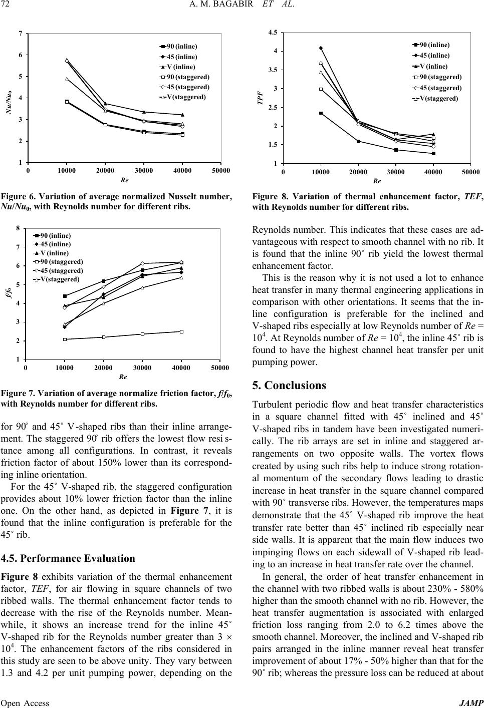 A. M. BAGABIR ET AL. Open Access JAMP 72 Figure 6. Variation of average normalized Nusselt number, Nu/Nu0, with Rey nolds number for di f f erent ribs. Figure 7. Variation of average normalize friction factor, f/f0, with Reynolds number for di f fe rent ribs. for 90˚ and 45˚ V-shaped ribs than their inline arrange- ment. The staggered 90˚ rib offers the lowest flow resis- tance among all configurations. In contrast, it reveals friction factor of about 150% lower than its correspond- ing inline orientation. For the 45˚ V-shaped rib, the staggered configuration provides about 10% lower friction factor than the inline one. On the other hand, as depicted in Figure 7, it is found that the inline configuration is preferable for the 45˚ rib. 4.5. Performance Evaluation Figure 8 exhibits variation of the thermal enhancement factor, TEF, for air flowing in square channels of two ribbed walls. The thermal enhancement factor tends to decrease with the rise of the Reynolds number. Mean- while, it shows an increase trend for the inline 45˚ V-shaped rib for the Reynolds number greater than 3 × 10⁴. The enhancement factors of the ribs considered in this study are seen to be above unity. They vary between 1.3 and 4.2 per unit pumping power, depending on the Figure 8. Variation of thermal enhancement factor, TEF, with Reynolds number for di f fe rent ribs. Reynolds number. This indicates that these cases are ad- vantageous with respect to smooth channel with no rib. It is found that the inline 90˚ rib yield the lowest thermal enhancement factor. This is the reason why it is not used a lot to enhance heat transfer in many thermal engineering applications in comparison with other orientations. It seems that the in- line configuration is preferable for the inclined and V-shaped ribs especially at low Reynolds number of Re = 104. At Reynolds number of Re = 104, the inline 45˚ rib i s found to have the highest channel heat transfer per unit pumping power. 5. Conclusions Turbulent periodic flow and heat transfer characteristics in a square channel fitted with 45˚ inclined and 45˚ V-shaped ribs in tandem have been investigated numeri- cally. The rib arrays are set in inline and staggered ar- rangements on two opposite walls. The vortex flows created by using such ribs help to induce strong rotation- al momentum of the secondary flows leading to drastic increase in heat transfer in the square channel compared with 90˚ transverse ribs. However, the temperatures maps demonstrate that the 45˚ V-shaped rib improve the heat transfer rate better than 45˚ inclined rib especially near side walls. It is apparent that the main flow induces two impinging flows on each sidewall of V-shaped rib lead- ing to an increase in heat transfer rate over the channel. In general, the order of heat transfer enhancement in the channel with two ribbed walls is abo ut 230% - 580% higher than the smooth channel with no rib. However, the heat transfer augmentation is associated with enlarged friction loss ranging from 2.0 to 6.2 times above the smooth channel. Moreover, the inclined and V-sha pe d rib pairs arranged in the inline manner reveal heat transfer improvement of about 17% - 50% higher than that for the 90˚ rib; whereas the pressure loss can be reduced at about 1 2 3 4 5 6 7 010000 20000 30000 40000 50000 Nu/Nu o Re 90 (inline) 45 (inline) V (inline) 90 (staggered) 45 (staggered) V(staggered) 1 2 3 4 5 6 7 8 010000 20000 30000 40000 50000 f/f o Re 90 (inline) 45 (inline) V (inline) 90 (staggered) 45 (staggered) V(staggered) 1 1.5 2 2.5 3 3.5 4 4.5 010000 20000 30000 40000 50000 TPF Re 90 (inline) 45 (inline) V (inline) 90 (staggered) 45 (staggered) V(staggered)  A. M. BAGABIR ET AL. Open Access JAMP 73 4% - 38% depending on Reynolds number. It is found that the staggered inclined ribs produce similar thermal profile as inline orientation but with higher friction factor. The staggered orientation lowers the thermal perfor- mance of 45˚ V-shape and reduces the friction factor. On the contrary, the staggered 90˚ transverse rib reveals thermal enhancement factor similar to inclined and V-shaped ribs for Reynolds number equal or higher than 2 × 10⁴. For Reynolds number of 104, the inline 45˚ rib reveals the optimum thermal enhancement factor. REFERENCES [1] J. Khamaj, “An Experimental Study of Heat Transfer in the Cooling Channels of Gas Turbine Rotor Blades,” PhD Thesis, University Wales, 2002. [2] O. Manca, S. Nardini and D. Ricci, “Numerical Study of Air Forced Convection in a Channel Provided with In- clined Ribs,” Frontiers in Heat and Mass Transfer, V ol. 2, 2011. http://dx.doi.org/10.5098/hmt.v2.1.3007 [3] J. C. Han, Y. M. Zhang and C. P. Lee, “Augmented Heat Transfer in Square Channels with Parallel, Crossed and V-Shaped Angled Ribs,” ASME, Journal of Heat Transfer, Vol. 113, 1991, pp. 590-596. http://dx.doi.org/10.1115/1.2910606 [4] H. Liu and J. Wang, “Numerical Investigation on Synthe- tical Performances of Fluid Flow and Heat Transfer of Semiattached Rib-Channels,” International Journal of Heat and Mass Transfer, Vol. 54, 2011, pp. 575-583. http://dx.doi.org/10.1016/j.ijheatmasstransfer.2010.09.01 3 [5] P. Promvonge, W. Changcharoen, S. Kwankaomeng and C. Thianpong, “Numerical Heat Transfer Study of Tur- bulent Square-Duct Flow Through Inline V-Shaped Dis- crete Ribs,” International Communications in Heat and Mass Transfer, Vol. 38, 2011, pp. 1392-1399. http://dx.doi.org/10.1016/j.icheatmasstransfer.2011.07.01 4 [6] R. Kamali and A. R. Binesh, “The Importance of Rib Shape Effects on the Local Heat Transfer and Flow Fric- tion Characteristics of Square Ducts with Ribbed Internal Surfaces,” International Communications in Heat and Mass Transfer, Vol. 35, 2008, pp. 1032-1040. http://dx.doi.org/10.1016/j.icheatmasstransfer.2008.04.01 2 [7] A. R. Sampath, “Effect of Rib Turbulators on Heat Tran- sfer Performance in Stationary Ribbed Channels,” PhD Thesis, Cleveland State University, 2009. [8] J. C. Han, “Heat Transfer and Friction in Channels with Two Opposite Rib Roughened Walls,” ASME Journal of Heat Transfer, Vol. 106, 1984, pp. 774-781. http://dx.doi.org/10.1115/1.3246751 [9] T. M. Liou and J. J. Hwang, “Turbulent Heat Transfer and Friction in Periodically Fully Developed Channel Flows,” ASME Journal of Heat Transfer, Vol. 114, 1992, pp. 56-64. http://dx.doi.org/10.1115/1.2911267 [10] A. Murata and S. Mochizuki, “Comparison between La- minar and Turbulent Heat Transfer in a Stationary Square Duct with Transverse or Angled Rib Turbulators,” Inter- national Journal of Heat and Mass Transfer, Vol. 44, 2001, pp. 1127-1141. http://dx.doi.org/10.1016/S0017-9310(00)00180-0 [11] S. V. Patankar, C. H. Liu and E. M. Sparrow, “Fully De- veloped Flow and Heat Transfer in Ducts Having Stream- wise-Periodic Variations of Cross-Sectional Area,” ASME Journal of Heat Transfer, Vol. 99, 1977, pp. 180-186. http://dx.doi.org/10.1115/1.3450666 [12] Fluent Corporation, “Fluent v6.3 User Guide,” 2006. [13] V. Yakhot and S. A. Orszag, “Renormalization Group Analysis of Turbulence: I. Basic Theory,” Journal of Scientific Computing, Vol. 1, No. 1, 1986, pp. 1-51. http://dx.doi.org/10.1007/BF01061452 [14] T. H. Shih, W. W. Liou, A. Shabbir, Z. Yang and J. Zhu, “A New k- ε Eddy-Viscosity Model for High Reynolds Number Turbulent Flows-Model Development and Vali- dation,” Computers Fluids, Vol. 24, No. 3, 1995, pp. 227- 238. http://dx.doi.org/10.1016/0045-7930(94)00032-T [15] F. R. Menter, “Two-Equat ion Eddy -Viscosity Turbulence Models for Engineering Applications,” AIAA Journal, Vol. 32, No. 8, 1994, pp. 1598-1605. http://dx.doi.org/10.2514/3.12149 Nomenclature D: Hydraulic diameter of channel width (m) e: Rib width (m) f: Friction factor for a ribbed channel f0: Friction factor for a smooth channel h: Rib height (m) or heat transfer coefficient H: Channel height ( m) k: Thermal conductivity (W/mK) Nu: Nusselt nu mber of a ribbed channel Nu0: Nusselt number of a smooth channel p: static pressure (pa) or rib pitch spacing (m) Pr: Prandtl number q: Heat flux (W/m2) Re: Reynol ds number TB: Bulk tem pe rature of flow (K) TS: Surface temperature (K) Tw: Wall temperature (K) TEF: Thermal enhancement factor u: Velocity (m/s) Um: Bulk velocity (m/s) W: Channel wi dth (m) ρ : Density (kg/m3) |