

Paper Menu >>
Journal Menu >>
 Journal of Applied Mathematics and Physics, 2013, 1, 62-64 Published Online November 2013 (http://www.scirp.org/journal/jamp) http://dx.doi.org/10.4236/jamp.2013.16013 Open Access JAMP Stress Analysis for Reactor Coolant Pump Nozzle of Nuclear Reactor Pressure Vessel Lijing Wen, Chao Guo*, Tieping Li, Chunming Zhang Nuclear and Radiation Safety Center, MEP, Beijing, China Email: [email protected], *[email protected] Received September 2013 ABSTRACT Integrated reactor structura l design makes the pressure vesse l itself and loads more complicated, so stress concentration makes strength failure easier at reactor coolant pump nozzle. The general purpose finite element program ANSYS/ WORKBENCH was used for 3D stress and fatigue analysis and the results of the evaluation are based on RCC-M crite- ria. The integrated reactor structural design is evaluated to demonstrate with applicable criteria and ANSYS/WORK- BENCH has better operability than ANSYS APDL on stress analysis of reactor pressure vessel. Keywords: Numerical Simulation; Reactor Pressure Vessel; Stress Analysis 1. Introduction Integrated reactor is new generation pressurized water reactor developed by China [1]. Reactor structure is highly integrated, for example, once through steam ge- nerator placed in a pressure vessel; reactor coolant pump is placed on the pressure vessel nozzles; press ure vessel fixed and supported the main pump, control rod drive mechanism and the top of the h eap struc ture. This struc- tural design can simplify a loop system and eliminate LBLOCA, but makes the pressure vessel itself and load s more complicated. So the stress analysis is necessary to ensure the effectiveness and safety of the design and the integrity of th e reactor pressure vessel. Most domestic researchers [2-5] using traditional ANSYS APDL for stress analysis and evaluation of reac- tor pressure vessel calculation. With the development of computing software, ANSYS, Inc. has developed AN- SYS/WORKBENCH software and pre-processing, cal- culation and post-processing become more convenient [6]. ANSYS/WORKBENCH is used in this paper. 2. Calculation Model According to the structure features of the reactor pressure vessel, the reactor pressure vessel cylinder and outlet nozzle is → are simplified: 1) According to RCC-M, surfacing layer is not exposed to any structural strength in criteria O, criteria C and cri- teria D. So surfacing layer is ignored in numerical model. 2) Bolt holes on reactor coolant pump nozzle and the effect of in-line casing and annular flow distribution plate are ignored. 3) To reduce edge effects influence on the reactor coolant pump nozzle, pressure vessel cylinder must be long enough in calculation model. According to RCC-M, the length in pressure vessel cylinder axial direction from the center line of the reactor coolant pump nozzle is at a length of 2.5 Rt at least, whe r e R = (R1 + R2)/2. R1 and R2 are the inside and outside radius of the pressure vessel cylinder, and t is the thickness of the pressure vessel cylinder. Three-dimensional finite element model of pressure vessel cylinder and outlet nozzle is built by ANSYS/ WORKBENCH program as shown in the Figure 1. 1 /4 model of pressure vessel cylinder and complete model of pressure vessel nozzle are built by hexahedral meshes with the size of 40 mm. Reactor pressure vessel design temperature is 343˚C. Pressure vessels and outlet nozzle materials are 16MND5 forgings. According to RCC-M Parameter Manual, 16 MND5 material parameters at 350˚C are shown in Table 1. 3. Evaluation Conditions, Loads and Boundary Conditions According to RCC-M, stress strength must conform to criteria O in the first operating condition when pressure vessel nozzle is analyzed. Self-weight, internal pressure and earthquake load are considered and each load is composed of six components. Force and moment are *Corresponding a uthor. 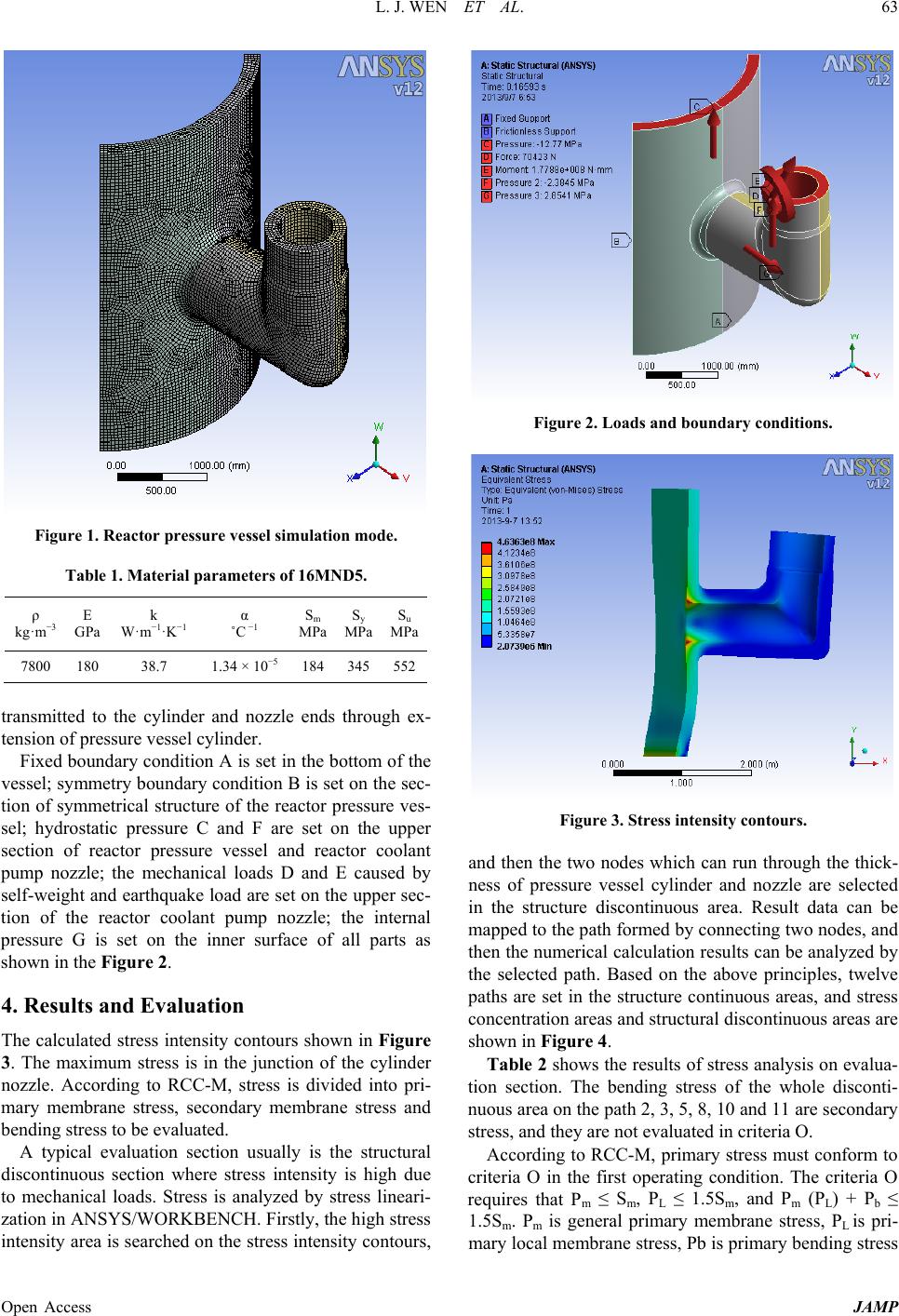 L. J. WEN ET AL. Open Access JAMP 63 Figure 1. Reac tor pressure vessel simulation mode. Table 1. Material parameters of 16MND5. ρ kg·m−3 E GPa k W·m−1·K−1 α ˚C −1 Sm MPa Sy MPa Su MPa 7800 180 38.7 1.34 × 10⁻⁵ 184 345 552 transmitted to the cylinder and nozzle ends through ex- tension of pressure vessel cylinder. Fixed boundary condition A is set in the bottom of the vessel; symmetry boundary condition B is set on the sec- tion of symmet r i c a l structur e of the reactor pressure ves- sel; hydrostatic pressure C and F are set on the upper section of reactor pressure vessel and reactor coolant pump nozzle; the mechanical loads D and E caused by self-weight and e ar thquake loa d are set on the upper sec- tion of the reactor coolant pump nozzle; the internal pressure G is set on the inner surface of all parts as shown in the Figure 2. 4. Results and Evaluation The calculated stress intensity contours shown in Figure 3. The maximum stress is in the junction of the cylinder nozzle. According to RCC-M, stress is divided into pri- mary membrane stress, secondary membrane stress and bending stress to be evaluated. A typical evaluation section usually is the structural discontinuous section where stress intensity is high due to mechanical loads. Stress is analyzed by stress lineari- zation in ANSYS/WORKBENCH. Firstly, the high stress intensity area is searched on the stress intensity contours, Figure 2. Load s an d bou ndary condi t i on s . Figure 3. Stress intensity contours. and then the two nodes which can run through the thick- ness of pressure vessel cylinder and nozzle are selected in the structure discontinuous area. Result data can be mapped to the path formed by connecting two nodes, and then the numerical calculation results can be analyzed by the selected path. Based on the above principles, twelve paths are set in the structure continuous areas, and stress concentration areas and structural discontinuous areas are shown in Figur e 4. Table 2 sho ws the results of stress analysis on evalua- tion section. The bending stress of the whole disconti- nuous area on the path 2, 3, 5, 8, 10 and 11 are secondary stress, and they are not evaluated in criteria O. According to RCC-M, primary stress must conform to criteria O in the first operating condition. The criteria O requires that Pm ≤ Sm, PL ≤ 1.5Sm, and Pm (PL) + Pb ≤ 1.5Sm. Pm is general primary membrane stress, PL is pri- mary local membrane stress, Pb is primary bending stress 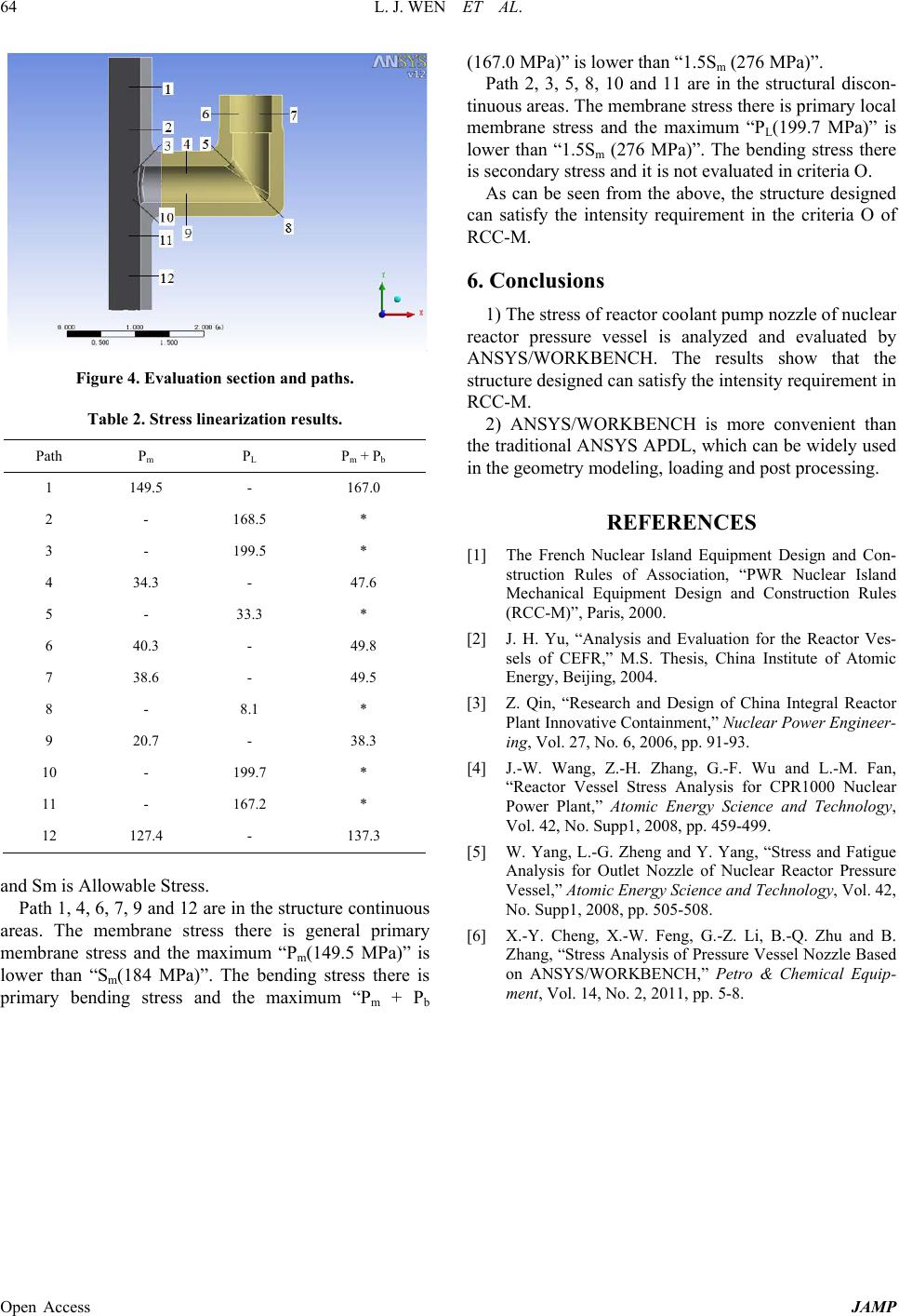 L. J. WEN ET AL. Open Access JAMP 64 Figure 4. Evaluation section and paths. Table 2. Stress linearization results. Path Pm PL Pm + Pb 1 149.5 - 167.0 2 - 168.5 * 3 - 199.5 * 4 34.3 - 47.6 5 - 33.3 * 6 40.3 - 49.8 7 38.6 - 49.5 8 - 8.1 * 9 20.7 - 38.3 10 - 199.7 * 11 - 167.2 * 12 127.4 - 137.3 and Sm is Allowable Stress. Path 1, 4, 6, 7, 9 and 12 are in the structure continuous areas. The membrane stre ss there is general primary membrane stress and the maximum “Pm(149.5 MPa)” is lower than “Sm(184 MPa)”. The bending stres s there is primary bending stress and the maximum “Pm + Pb (167.0 MP a)” is lowe r than “1.5Sm (276 MPa)”. Path 2, 3, 5, 8, 10 and 11 are in the structural discon- tinuous areas. The membrane stress th ere is primary local membrane stress and the maximum “PL(199.7 MPa)” is lower than “1.5Sm (276 MPa) ”. The bending stress there is secondary stress and it is not evaluated in criteria O. As can be seen from the above, the stru ctu re designed can satisfy the intensity requirement in the criteria O of RCC-M. 6. Conclusions 1) The str ess of reactor coolant pump nozzle of nuclear reactor pressure vessel is analyzed and evaluated by ANSYS/WORKBENCH. The results show that the structure designed c an satisfy the intensity requirement in RCC-M. 2) ANSYS/WORKBENCH is more convenient than the traditional ANSYS APDL, whi ch can be widely used in the geometry modeling, loading and post processing. REFERENCES [1] The French Nuclear Island Equipment Design and Con- struction Rules of Association, “PWR Nuclear Island Mechanical Equipment Design and Construction Rules (RCC-M)”, Paris, 2000. [2] J. H. Yu, “Analysis and Evaluation for the Reactor Ves- sels of CEFR,” M.S. Thesis, China Institute of Atomic Energy, Beijing, 2004. [3] Z. Qin, “Research and Design of China Integral Reactor Plant Innovative Containment,” Nuclear Power Engineer- ing, Vol. 27, No. 6, 2006, pp. 91-93. [4] J.-W. Wang, Z.-H. Zhang, G.-F. Wu and L.-M. Fan, “Reactor Vessel Stress Analysis for CPR1000 Nuclear Power Plant,” Atomic Energy Science and Technology, Vol. 42, No. Supp1, 2008, pp. 459-499. [5] W. Yang, L.-G. Zheng and Y. Yang, “Stress and Fatigue Analysis for Outlet Nozzle of Nuclear Reactor Pressure Vessel,” Atomic Energy Science and Technology, Vol. 42, No. Supp1, 2008, pp. 505-508. [6] X.-Y. Cheng, X.-W. Feng, G.-Z. Li, B.-Q. Zhu and B. Zhang, “Stress Analysis of Pressure Vessel Nozzle Based on ANSYS/WORKBENCH,” Petro & Chemical Equip- ment, Vol. 14, No. 2, 2011, pp. 5-8. |